SPF-manualv0.1_金龙收集
COLOR LCD FISH FINDER FF50 维修手册

Before You Begin
Symbols Used In This Manual
Related Symbols Marks In this manual, and on the equipment, we use several warning signs to call your attention to important to items that, if not handled correctly, could present danger to yourself or property. These warning note classifications are as described below. Please be fully aware of the importance of these items before using this manual.
Warning Label You can see the warning label on the top of the unit. Do you attempt to remove the warning label from the unit or impair or modify it.
2
Байду номын сангаас
Usage Hints
Simulator
6.5 inch Color LCD (TFT) 234 320 dots (Screen Size 133 mm 97 mm) 8 or 16 Color Gradation with 2 Patterns 10 steps 10 steps Auto or Manual
5 to 1,500 m 10 to 5,000 ft 3 to 1,000 fm Auto or Manual 0 to 1,000m 0 to 3,000ft 0 to 600fm 200 kHz/50 kHz (Dual Frequency) 600 W RMS (4,800W P-P) 100 steps Meter, Feet, Fathom, SP (0.3000 to 1.9999 m) Knots, Mile/h, Km/h Selectable (0 to 15 level) Selectable (OFF, IR1, IR2) Selectable (Short, Mid, Long) 32.0 degree Fahrenheit to 100.0 degree Fahrenheit (0.0 degree Centigrade to 40.0 degree Centigrade) 0 to 70 Knots (Only at the STD/ 0 to 999 NM Navigation type 1 or 2) 1) STD (LF or HF) 2) STD (LF)/STD (HF) 3) STD/A-Scope (LF or HF) 4) STD/A-Scope (LF)/STD/A-Scope (HF) 5) STD/Zoom (LF or HF) 6) STD/Auto Zoom (LF or HF) 7) STD/Bottom Lock (LF or HF) 8) STD/Bottom Discrimination (LF or HF) 9) STD/Dual Frequency Mixed 10) STD/Navigation type1 (LF or HF) 11) STD/Navigation type2 (LF or HF) Built-In
GreenKeeper 212用户指南说明书

User’s Guide Automatic Sprinkler System ControllerGreenKeeper 212 Features:• Easily Expandable Up To 12 StationsWith 2-Station Plug-In Modules• 3 Watering Programs With:ON- Calendar, Interval and Odd/ Even DaysMANUALNEXTSTARTPROGRAMS- 1 Min. to 4 Hrs. Zone Run TimeA B COFF- 4 Start Times Per Program• Battery Back-Up• Automatic Pump Start• Seasonal Run Time Adjust• Rain Delay• Rain Sensor ReadyR• Remote Control Ready• Snap-In Wire Connectors Resumen del contenido incluido en la página 2 Resumen del contenido incluido en la página 3 Table of Contents Introduction and Set Up Installation GreenKeeper 212 Components......................2-5 Mounting The Co
COMOSO AGE-Z 三指中心抓取器 Z 补偿单元说明书

Compensation Compensation309C O M P E N S A T I O NAGE-ZLight LoadCompensation unit for handling of w orkpieces with different height t olerances. The compensation unit c ompensates the horizontal offset of the placing position.Compensation Unit AGE-Z 803-Finger Centric GripperPZN-plus 80 withworkpiece-specific gripper fingersSizes 050 .. 080Payload 1 kg .. 5 kg Compensation paths Z ± 10 mmExample for applicationAGE-ZLight LoadISO flange patternfor easy mounting to most robot types without additional adapter platesLocking devicefor rigid switching of the unit in a defined extended or retracted positionCompact designfor minimum overall heightCan be combined with AGE-XY without additionaladapter plateCompensation unit with Z-axis yielding.Compensation UnitArea of applicationMounting, palletizing and insertion of workpiecesBenefitsGeneral information on the seriesCompensation path Z-direction: up to 10 mm Guides Solid guides ActuationPneumatic, filtered compressed air (10 µm): dry, lubricated or non-lubricated Operating pressure range 2 bar to 8 barMonitoring of the Z-stroke By magnetic switchesAmbient temperature 5° to 60° C MaterialAluminum alloy, hard-anodized.Functional components of hardened steel.Warranty 24 months311AGE-ZLight LoadHousingweight-reduced due to use of a hard-anodized, high-strength aluminum alloy Compression Springsfor defined pressure forces during placingMonitoring GrooveStroke monitoring of the locking piston with magnetic switches Ball Guides are Free of Playfor large maximum moments at a minimum sizeThe compensation unit AGE-Z enables a Z-compensation of different pickup and p lacing positions.The compensation unit is guided by a ball guide without play.Compression springs define the rigidity of the AGE-Z. which can be increased bya dditional actuation of the pneumatic cylinder.The cylinder also enables locking of the unit during dynamic movements. The r etracted and extended positions are monitored by means of magnetic switches.Function descriptionSectional diagramAGE-ZLight LoadExtreme ambient conditionsPlease be aware that use under extreme conditions (e.g. with coolants, or in the presence of casting dust or abrasive dust) can significantly reduce the tool life of these units, for which we can make no guarantee. In many cases, however, we have a solution. Please contact us.General information on the seriesFittingsMagnetic switch MMSSensor cableAccessoriesThe specific size of the desired accessories, availability for the model and the name and ID no. can be found in the additional diagrams following each model.For further information on our accessories, please consult the “Accessories” section of the catalog.313AGE-Z 050Light LoadTechnical dataDesignationAGE-Z-050ID 0324452Workpiece weight (recommendation)[kg] 1.0 Compensation stroke[mm]8.0Mounting, round mechanical interface ISO 9409-50-4-M6Spring force[N]10 - 30Extend piston force at 6 bar [N]300Retract piston force at 6 bar [N]270Weight[kg]0.35Forces and momentsLoad diagram Deflection of the AGE-Z under loadAGE-Z 050Light LoadMain viewsA Connection lockedB Air connection unlocked ᕃ Connection, robot-side ᕄ Connection, tool-sideᕇ Through-bores for screw connection with screw (enclosed)315www .s c h u n k .c o m AGE-Z 050Light LoadSensor systemEnd position monitoring:Electronic magnetic switches, for mounting in C-slot Designation ID Recommended product MMS 22-S-M5-NPN 0301439MMS 22-S-M5-NPN-SA 0301449MMS 22-S-M5-PNP 0301438MMS 22-S-M5-PNP-SA 0301448MMS 22-S-M8-NPN 0301433MMS 22-S-M8-NPN-SA 0301443MMS 22-S-M8-PNP 0301432•MMS 22-S-M8-PNP-SA 0301442MMSK 22-S-NPN 0301435MMSK 22-S-PNP 0301434 Two sensors (closers/S) are required for each compensation unit, plus extension cables as an option.Extension cable for proximity switches/magnetic switches Designation ID GK 3-M80301622GK 3-M5-PNP/NPN 0301652KV 10-M120301596KV 10-M80301496KV 20-M120301597KV 20-M80301497KV 3-M120301595KV 3-M80301495W 3-M120301503W 5-M120301507W 3-M5-PNP/NPN 0301650WK 3-M80301594WK 3-M8 NPN 0301602WK 5-M80301502WK 5-M8 NPN 9641116Please note the minimum permitted bending radii for the sensor cables, which aregenerally 35 mm.AGE-Z 050Light Load317AGE-Z 063Light LoadTechnical dataDesignationAGE-Z-063ID 032465Workpiece weight (recommendation)[kg] 2.0Compensation stroke[mm]8.0Mounting,round mechanical interface ISO 9409-63-4-M6Spring force[N]20–60Extend piston force at 6bar [N]560Retract piston force at 6bar [N]500Weight[kg]0.6Forces and momentsLoad diagram Deflection of the AGE-Z underloadAGE-Z 063Light LoadMain viewsA Locked air connectionB Unlocked air connection ᕃ Robot-side connection ᕄ Tool-side connectionᕇ Through-bore for screw connection with screw (enclosed)AGE-Z 063Light LoadSensor systemEnd position monitoring:Electronic magnetic switches, for mounting in C-slot Designation ID Recommended product MMS 22-S-M5-NPN 0301439MMS 22-S-M5-NPN-SA 0301449MMS 22-S-M5-PNP 0301438MMS 22-S-M5-PNP-SA 0301448MMS 22-S-M8-NPN 0301433MMS 22-S-M8-NPN-SA 0301443MMS 22-S-M8-PNP 0301432•MMS 22-S-M8-PNP-SA 0301442MMSK 22-S-NPN 0301435MMSK 22-S-PNP 0301434 Two sensors (closers/S) are required for each compensation unit, plus extension cables as an option.Extension cable for proximity switches/magnetic switches Designation ID GK 3-M80301622GK 3-M5-PNP/NPN 0301652KV 10-M120301596KV 10-M80301496KV 20-M120301597KV 20-M80301497KV 3-M120301595KV 3-M80301495W 3-M120301503W 5-M120301507W 3-M5-PNP/NPN 0301650WK 3-M80301594WK 3-M8 NPN 0301602WK 5-M80301502WK 5-M8 NPN 9641116Please note the minimum permitted bending radii for the sensor cables, which aregenerally 35 mm.AGE-Z 063Light LoadAGE-Z 080Light LoadTechnical dataDesignationAGE-Z-080ID 0324482Workpiece weight (recommendation)[kg] 5.0Compensation stroke[mm]10.0Mounting,round mechanical interface ISO 9409-80-6-M8Spring force[N]40-240Extend piston force at 6bar [N]840Retract piston force at 6bar [N]600Weight[kg]1.1Forces and momentsLoad diagram Deflection of the AGE-Z underloadAGE-Z 080Light LoadMain viewsA Locked air connectionB Unlocked air connection ᕃ Robot-side connection ᕄ Tool-side connectionᕇ Through-bore for screw connection with screw (enclosed)AGE-Z 080Light LoadSensor systemEnd position monitoring:Electronic magnetic switches, for mounting in C-slot Designation ID Recommended product MMS 22-S-M5-NPN 0301439MMS 22-S-M5-NPN-SA 0301449MMS 22-S-M5-PNP 0301438MMS 22-S-M5-PNP-SA 0301448MMS 22-S-M8-NPN 0301433MMS 22-S-M8-NPN-SA 0301443MMS 22-S-M8-PNP 0301432•MMS 22-S-M8-PNP-SA 0301442MMSK 22-S-NPN 0301435MMSK 22-S-PNP 0301434 Two sensors (closers/S) are required for each compensation unit, plus extension cables as an option.Extension cable for proximity switches/magnetic switches Designation ID GK 3-M80301622GK 3-M5-PNP/NPN 0301652KV 10-M120301596KV 10-M80301496KV 20-M120301597KV 20-M80301497KV 3-M120301595KV 3-M80301495W 3-M120301503W 5-M120301507W 3-M5-PNP/NPN 0301650WK 3-M80301594WK 3-M8 NPN 0301602WK 5-M80301502WK 5-M8 NPN 9641116Please note the minimum permitted bending radi for the sensor cables, which aregenerally 35 mm.AGE-Z 080Light Load 。
PoC手册 - _简介及环境准备

标准化实施方案| 白皮书| Citrix XenDesktopPOC标准化实施指南基础环境简介及环境准备版本:v1.0第1章POC手册使用介绍 (3)1.1 POC整体流程介绍及手册主要章节 (3)第2章环境准备 (4)2.1 POC环境整体构架示意图 (4)2.2 POC环境准备检查单 (4)2.3 POC环境主机及虚拟机配置列表 (6)产品版本 (7)修正历史 (7)第1章POC手册使用介绍本POC手册是Citrix虚拟桌面和虚拟应用测试工具包的一部分,提供了进行测试具体执行阶段所需要的分步指导。
在具体开始实际测试工作前,应该已经和客户确认的测试计划,并且就环境的准备等事项,和客户进行了充分的沟通,确认环境准备完毕。
本手册包含了最基本的测试环境的搭建,也包含了一些常用测试案例的测试步骤以及环境优化的指南。
在实际测试中,可以根据实际的测试计划进行必要的调整。
1.1 POC整体流程介绍及手册主要章节以下列出了本手册包含的主要章节内容基础测试环境搭建及优化1. 基础环境LAB 1 XenServer安装及虚拟主机环境配置(包括XenServer,ISOLibrary,OS基础镜像模板)2. 基础环境LAB 2 基础构架环境安装a. AD,DDC,XA操作系统安装,Windows 7,Windows XP OS安装(从模板生成)b. 配置AD,DHCP,DNS,并将其他主机加入域c. 建立测试账号,OU和用户组3. 基础环境LAB 3 XenDesktop安装和基本配置(含License服务)4. 基础环境LAB 4 XenApp安装和基本配置,WI配置5. 基础环境LAB 5 使用XenApp发布Win7体验的共享桌面6. 基础环境LAB 6 客户端配置和访问7. 基础环境LAB 7 环境优化指南具体测试项目8. 具体测试LAB 1 桌面生命周期管理9. 具体测试LAB 2 策略配置及会话管理测试10. 具体测试LAB 3 用户体验、带宽测试和外设支持测试第2章环境准备2.1 POC环境整体构架示意图DHCPSQL Server ActiveDirectory基础架构服务器层XenAppDesktopDeliveryControllerWebInterfaceXenDesktop/XenApp场XenServer虚拟桌面池VM VM VM VMVM VM VM VM专有桌面池池动桌面池共享桌面池Share FileUser Profile共享存储瘦客户端普通桌面PC平板电脑手机内网用户家分支机构平板电脑手机NetScaler Or VPX物理桌面池2.2 POC环境准备检查单基础环境准备物理服务器准备□硬件服务器是否满足测试要求,推荐采用2路6核,16G内存以上□CPU开启VT或AMD/V功能-BIOS中设定□CPU禁用C-State-BIOS中设定□禁用Multi-thread-BIOS中设定□启用Remote console(如果是IBM服务器) -BIOS中设定□确定服务器的BIOS日期是否配置正确-BIOS中设定□禁用Executive lock bit-BIOS中设定□本地磁盘建议设置成RAID1或RAID 1/0□如果磁盘以前安装过VMware 或其它OS, 重新初始化RAID10□一台Windows 7或者WinXP客户端,作为管理客户端思杰测试许可证□准备测试许可证文件,同时确定许可证文件对应的主机名并区分大小写(本手册中,许可服务器主机名为“CTXDDC”)□测试许可证有效期至少1个月以上安装映像文件□Windows 2008 R2 SP1和介质□Windows 2003 SP2 (可选)□Windows XP SP3□Windows 7 SP1□Citrix XenDesktop ISO (版本5.6)□Citrix XenApp ISO (版本6.5,版本5.0 FP2(可选))□Citrix XenServer 光盘(版本6.1)IP地址□服务器固定IP地址至少5个(手册中使用192.168.x.151-154)□虚拟桌面VM地址(DHCP)2-10个(手册中使用192.168.x.171-200)□2.3 POC环境主机及虚拟机配置列表Hostname 角色安装软件IP OS 本地存储内存备注Xenserver01 虚拟主机(物理)XenServer6.0.2192.168.x.1 XenServer 16GCTXAD 活动目录域控制器2008DNSDHCP192.168.x.151Server2008R2Ent Sp1C: 2GB域名citrixlab.localCTXDDC XenDesktopDDCWILicenseXenDesktop5.6 FP1192.168.x.152Server2008R2Ent Sp1C:40GB 4GB注意,License服务器的主机名必须和license文件的主机名严格一致,并且区分大小写。
黑翼飞行模拟器用户手册说明书

IntroductionThe Blackwing BW 635RG is an ultralight two-seater aeroplane designed for recreational flying and training purposes. It features a sleek and modern design, with a composite airframe and a low-wing configuration. The Blackwing has a cruising speed of up to 120 knots and a range of approximately 700 nautical miles, making it suitable for both short and long-distance flights. The cockpit is equipped with state-of-the-art avionics, including a glass cockpit display and an autopilot system. The Blackwing is also known for its superior handling and stability, making it a popular choice among flying enthusiasts and flight schools. The BW 635RG is powered by the venerable Rotax 915 iS engine.Development Credits:Mal Cartwright Product LeadRuss White3D Modelling, Interior and Exterior TexturingJack Lavigne IntegrationHarry Stringer AnimationPropAir Flight Model and SystemsJordan Gough ManualWith special thanks to our Beta Testers:Rob Abernathy John BurgessNick Cooper John DowMatt McGee Darryl WightmanTable of ContentsIntroduction (2)Development Credits: (2)With special thanks to our Beta Testers: (2)Table of Contents (3)Notes on Hardware (4)Overview (5)Aircraft Limitations (6)Airspeed Limitations (6)Engine Limitations (6)Operating Conditions (6)Fuel (7)Other Limitations (7)Emergency Procedures (8)Engine Failure on the Take-off Roll (8)Engine Failure after Take-off (8)Glide Performance (8)Emergency Landing (9)Spin Recovery (9)Normal Procedures (10)Before Starting Engine (10)Starting Engine (10)Before Taxiing (11)Taxiing (11)Engine Runup (11)Before Take-off (11)Take-Off (12)Initial Climb (12)Cruise Climb (12)Cruise (12)Landing (13)Balked Landing (13)After Landing (13)Securing Aircraft (14)Basic Performance (15)Stall Speeds (15)Take-Off Performance (15)Landing Performance (16)Systems Description (17)Instrument Panel Layout (17)Switch Logic and Electrical System (18)Master Switch (18)Fuel Pump Switch (19)LAND/TAXI Switch (19)Strobe/Nav Switch (19)Electrical System Diagram (20)Engine (21)Propeller (21)Fuel (21)Notes on HardwareDue to the unusual 3-position switches in this aircraft, conventional hardware 2position toggle switches (eg. strobe or nav light switches) cannot be translated tothe single 3-position switch which combine these.Additionally, as this aircraft utilises a single level power control (throttle), conventional throttle/prop/mixture hardware may interfere with the function of this system, and not work as intended. It is recommended to place your propeller and mixture levers in the IDLE position, and not move them while the engine is running.OverviewThe Orbx BW 635RG has been developed using official documentation and Computer Aided Design (CAD) resources from Blackwing Sweden. As a result, the aeroplane has been created through masterful modelling, texturing, systems integration, and flight model development.Figure 1 – Aircraft 3-viewAircraft DimensionsLength 6.6m Height 2.2m Wingspan8.4mWeightsBasic Empty Weight 375kg Maximum Take-off Weight 600kg Maximum Fuel Capacity (Litres)130LThe content in this manual and the operation of the BW 635RG in Microsoft Flight Simulator strictly must not be used as reference material in any form for operating the real aircraft.Aircraft LimitationsAirspeed LimitationsAirspeed Description Airspeed (KIAS) RemarksVne Never Exceed Speed 157 Must not exceed this speed in any operation.Va Manoeuvring Speed 109 If full or abrupt control deflection is made, the airframe may be overstressed.Vfe1 Max flap extended speed20 degrees90 Maximum speed for flaps 20°Vfe2 Max flap extended speed35-45 degrees 70 Maximum speed for flaps 35-45°Vlo Maximum landing gearoperating speed 70Do not extended or retract the landing gearabove this speed.Vle Maximum landing gear extended speed 90 Do not exceed this speed with the landing gearalready down.Vs0 Stall speed flaps/gearextended 38 Stall speed with gear down/flaps >0° and in level flight at MTOWVs1 Stall speed clean 49 Stall speed flaps retracted, gear up and in level flight at MTOWEngine LimitationsEngineEngine Manufacturer Rotax Engine Model Rotax 915 iSMaximum Power Take-off (Max 5 min.) 141 hp Continuous 135 hpMaximum RPM Take-off (Max 5 min.) 5800 Continuous 5500Critical Altitude 15000ft AMSL Maximum OperatingAltitude23000ft AMSL Operating ConditionsAerobatic manoeuvres, flight in IFR conditionsand flights in icing conditions are prohibited inthis aircraft.FuelFuel TanksLeft Right Litres US Gal Litres US GalTotal Fuel in Tank 67.5 17.8 62.5 16.5Unusable Fuel 2.5 0.7 2.5 0.7 Total Useable Fuel in Tanks 66.5 17.6 61.5 16.2Other LimitationsMaximum demonstrated crosswind for the BW 635RG is 20 knots.Emergency ProceduresNote: The following procedures have been modified to be suitable for simulation. It does not cover emergencies that are a) not simulated and b) not reasonable. Checklist items from the real procedures have been omitted and these procedures must not under any circumstances be used for training purposes.Engine Failure on the Take-off RollThrottle: IDLEIgnition: OFFFuel Pump: MAIN (DOWN POS)Brakes: APPLYWhen stopped: SECURE AIRCRAFTEngine Failure after Take-offNose: IMMEDIATELY LOWERAirspeed: 65 KNOTSLanding Area: DETERMINE WITHIN 30° OF NOSEFlaps: USE AS REQUIREDLanding Gear: USE DESCRETIONFuel Selector: OFFIgnition: OFFMaster Switch: OFFGlide PerformanceThe BW 635RG, the approximate performance for a glide is 65 KIAS which willgive approximately a 545ft/min rate of descent in the clean configuration.Glide performance will degrade significantly on extension of flaps and landinggear.Emergency LandingAirspeed: 65 KIASField: PICK BEST OPTIONLanding Gear: USE DISCRETION DEPENDING ON FIELD TYPEFlaps: AS REQUIREDFuel Selector: OFFIgnition: OFFFuel Pump: MAIN (down)Master Switch: OFF BEFORE LANDINGSpin RecoveryThrottle: IDLEControl Stick: AILERON NEUTRALRudder: FULL OPPOSITE TO DIRECTION OF ROTATIONControl Stick: POSITIVELY FORWARD OF NEUTRALRudder: NEUTRAL WHEN ROTATION STOPSControl Stick: SMOOTHLY PULL OUT OF DIVEWARNING:INTENTIONAL SPINS ARE NOT APPROVED INTHIS AIRCRAFT.Normal ProceduresNote: The pre-flight inspection portion of the normal procedures has been removed due to impracticality in the simulator.Before Starting EngineIgnition: OFFMaster Switch: OFF (down)Backup Battery: OFF/AUTO (down)Landing Gear Lever: DOWNCircuit Breakers: INCanopy CLOSED (CLICKING THE LATCHON THE INSIDE LEFT SIDEWALL.) Starting EngineParking Brake: HOLD TOE BRAKES AND ENGAGE PARKINGBRAKEMaster Switch: ENGINE START (middle position)Fuel Selector: SETFuel Gauge: CHECKFuel Pump: BOTH (up)Ignition: BOTHNav Lights: STROBE (middle position)Throttle: SET ½-1 INCH OPENIgnition: STARTOil Pressure: GREEN WITHIN 10 SECWarnings: NONEBefore TaxiingMaster Switch: NORMAL OPERATION (up)Altimeter: SETAvionics: SETParking Brake: DISENGAGETaxiingInstruments: CHECKED (COMPASS/HSI/BALL/ATT) Engine RunupParking Brake: ENGAGERPM: 2500 RPMFuel Pump: CYCLE, CHECK FUEL PRESSUREIdle: CHECK IDLE 1800 +/- 100 RPM Before Take-offCanopy: CLOSED AND LOCKEDFlaps: 1 STAGE (20°)Elevator Trim: SET FOR TAKE-OFFEngine Instruments: NORMALLanding Light: ON (up)Controls: FULL FREE AND CORRECT MOVEMENTParking Brake: DISENGAGETake-OffThrottle: FULLControls: NEUTRAL45 Knots: ROTATEAccelerate: NOSE ON HORIZON, ACCEL TO 80 KIASPositive Rate of Climb: GEAR UPLanding Light: OFF (down)Flaps: RETRACT ABOVE 500’ AGLInitial ClimbThrottle: MAX CONTINUOUS (5500 RPM)Airspeed: 90 KIASFuel Pump: MAIN (down) ABOVE 500’ AGL Cruise ClimbThrottle: MAX CONTINUOUS (5500 RPM)Airspeed: 130 KIASCruiseThrottle: 55-75% PowerAirspeed: 120-157 KIAS (<130 KIAS IN TURB)LandingFuel: QTY CHECKEDFuel Selector: FULLEST TANKFuel Pump: BOTH (up position)Airspeed: 90 KIASFlaps: EXTEND FLAP 1 <90 KIASDownwind Airspeed: 65 KIASLanding Gear: DOWN @ 65 KIAS; CHECK 3 GREENLanding Light: ON (up position)Base Leg: EXTEND FLAP 2 < 65 KIASFinal Approach Airspeed: 60 KIASBalked LandingThrottle: SMOOTHLY INCREASEAirspeed: 60 KIASTrim: COURSE TRIM TO RELIEVE PRESSUREFlaps: RETRACT TO POSITION 1 (20°)Gear: UPTrim: TRIM FOR CLIMBAfter LandingFlaps: RETRACTExterior Lights: AS REQ’DFuel Pump: MAIN (down)Securing AircraftParking Brake: ENGAGEDThrottle: IDLESwitches: ALL OFF EXCEPT ACL AND MASTERIgnition: OFFNav Lights: OFF (down)Master Switch: OFFBasic PerformanceStall SpeedsMTOW 600kg | CG 32% MAC | Power Idle | Level FlightFlap Position Stall Speed (KIAS) 0° 49 20° 44 35° 39 45°38Take-Off PerformanceMTOW | ISA CONDITIONS | SEA LEVEL | FLAPS 1 (20°) | MTOW (600kg)Cruise PerformanceRunway Surface Ground RollOver 50ft Obstacleft mft mPaved Runway328 100 656 200 Unpaved (Grass) Runway 361110689208Pressure Altitude Power (%) TAS Fuel Flow LPH MAP (inHg) Endurance(hr)Range (nm) 500055 161 19.7 30 5.8 941 65 170 23.3 34.1 4.9 827 7517826.937.44.1738Landing PerformanceMTOW | ISA CONDITIONS | FLAPS 2 (35°) | MTOW (600kg) | Speed 1.3 x VsoRunway Surface Ground Roll Over 50ft Obstacle ft m ft mPaved Runway 525 160 951 290 Unpaved (Grass) Runway 558 170 984 300Systems Description Instrument Panel LayoutSwitch Logic and Electrical SystemThe electrical switches in the BW 635RG are 3-position switches. These are generally known as “DOWN”, “MIDDLE” and “UP”. They are briefly explained below.Master SwitchThe MASTER switch functions in a unique way, with the following switch logic:1.When the MASTER switch is DOWN, all battery power is off. There will beno electrical power provided to the aircraft.•Note: The engine CANNOT be shut down when the master switch isoff. Electrical power must be present for the engine to turn off.2.When the MASTER switch is in the MIDDLE (Engine Start) position, limitedsystem functionality will be present. The backup battery will be activatedand power the following systems:•Primary Flight Display•Compass•AHRS (Attitude Heading Reference System)•Radio3.When the MASTER switch is UP (Normal Operation), full electrical supplywill be provided to the aircraft. The following systems will be powered on: •Note: the engine CANNOT be started with the MASTER switch in theUP position. If the engine won’t start, check the switch is in theMIDDLE position•Multi-Function Display•Transponder•Autopilot•Audio panel•STBY instruments•Pitot Heat•Main battery is disconnected from running engine. Alternatorprovides power.See Section NORMAL PROCEDURES for positioning of the MASTER switch.Fuel Pump SwitchThe Fuel Pump switch also has some advanced logic to it, due to two fuel pumpsbeing present, however, to put it simply, it operates in the following way:1.In the DOWN position, the main fuel pump is in use.2.In the MIDDLE position, the auxiliary fuel pump is in use.3.In the UP position, both fuel pumps will be on.LAND/TAXI SwitchThe LAND/TAXI switch powers the Taxi and Landing lights. It operates in the following logic:1.In the DOWN position, both lights will be OFF.2.In the MIDDLE position, the taxi light will switch on when the landinggear is extended.3.In the UP position, the Landing Light will switch on when the landinggear is extended.Strobe/Nav SwitchThe Strobe/Nav switch powers the Navigation (Red/Green) and Strobe (flashingwhite) lights. It operates in the following logic:1.In the DOWN position, both lights will be OFF.2.In the MIDDLE position, the STROBE light will be on.3.In the UP position, both the strobe and Nav lights will be on.Electrical System DiagramThe BW 635RG’s electrical system is modelled in the following way in Microsoft Flight Simulator.Because the starter system is connected to the BACKUP BUS, this means you cannot start the engine with the MASTER switch in the UP position, due to the BACKUP BUS being disconnected from the circuit once the MAIN BAT BUS is powered.Page 21 of 21User Guide v1.0 –RevisionEngineThe BW 635RG is powered by the Rotax 915iS. The Rotax 915iS is a four-stroke, four-cylinder, fuel-injected, turbocharged aircraft engine with a maximum power output of141 horsepower. The engine utilizes electronic fuel injection (EFI) technology toprovide precise fuel delivery and improved fuel efficiency. It also features a modernliquid-cooling system and a dual electronic ignition system for reliable performance.The Rotax 915iS engine has a maximum operating RPM of 5,200, with a recommended continuous operation range of 5,000 RPM or less.PropellerThe propeller is a 3-blade wood-composite design, which is hydraulically adjustable for operation at various pitch angles, controlled independently of the pilot. The propeller is linked to the engine through an electronically controlled governor, where RPM isadjusted in accordance with the position of the throttle control. This pitch curve cannot be adjusted in flight, however is designed to ensure maximum performance in allphases of flight.FuelBoth wings have fuel tanks, which are fed to the engine via electric fuel pumps. Fuelsystem information is fed via sensors to the Garmin avionics suite and can be viewedon the displays inside the cockpit.AIRPLANE WEIGHTSBasic Empty Weight……………………….…375 KgMaximum Takeoff Weight…………………..600 KgMaximum Fuel Weight………………………...95 Kg Maximum Landing Weight………………….600 Kg TANK USABLE FUEL LEFT WING TANK67.5 litres 17.8 US Gallons RIGHT WING TANK62.5 litres 16.5 US Gallons TOTAL 130 litres34.3 US GallonsFUEL CAPACITY AIRSPEEDS Never Exceed Speed ……….…………….173 KIAS Max Structural Cruising Speed…………..156 KIAS Maneuvering Speed MTOW……………….109 KIAS Initial Climb………………………………………80 KIASBest Angle Climb……………………………….75 KIASBest Rate of Climb……………………………..90 KIASMax Flap Ext 20°……………………..............90 KIASMax Flap Ext 35-45°……………………………70 KIASMax Landing Gear Operation……………….70 KIASMax Landing Gear Extended………………..90 KIASPlanned Cruise TAS………………………….130 KIASFinal Approach Speed………………………..60 KIAS POWERPLANT LIMITATIONSENGINE LIMITS (RPM)Take-off (5 Minutes)………....5800 RPM Max Continuous……………….5500 RPMALTITUDE LIMITSMaximum Operating Altitude………………23 000ftFor Microsoft Flight Simulator Use Only0-12023 Orbx Simulation Systems Pty. Ltd BW 635RG QUICK REFERENCESHEETIssued: 21 Apr 2023Revised: 21 Apr 20230-2PROCEDURESBEFORE STARTING ENGINEPreflight Inspection………………………….COMPLETECrew Briefing………………………………….COMPLETEIgnition…………………………………………………….OFFMaster Switch…………………………………………..OFFBackup Battery …..…………………………….OFF/AUTOLanding Gear Lever………………………………..DOWNCircuit Breakers…………………………………………..IN Canopy………………………………………………CLOSED STARTING ENGINEArea……………………………………………………..CLEARParking Brake……………….HOLD TOE BRAKES ANDENGAGEMaster Switch …..……………….ENGINE START (MID)Fuel Selector…………………………………………….SETFuel Pump………………………………………BOTH (UP)Ignition………………………………………………….BOTHExternal Lights……………………………………..AS REQThrottle ………………………..………..Τ12-1 INCH OPENIgnition………………………………………………….START AFTER START Oil Pressure.…………………………………………RISING Master Switch ……………………………..NORMAL (UP)Radios………………………………………………………SET Altimeter…………………………………………………..SET ATIS and Clearance…………………………..OBTAINEDBEFORE TAXIBrakes/Park Brake ………………………….DISENGAGEFlight Instruments……………………………..CHECKEDCompass…………………………………………CHECKED BEFORE TAKEOFFCanopy/Harnesses………………………………SECURE Flaps…………………………………….……1 STAGE (20°)Trim ..……………………………………SET FOR TAKEOFF Flight Instruments………………………………………SET Engine Instruments………………CHECKED NORMAL Avionics…………………………………………………….SET External Lights………………………………………AS REQ Flight Controls…………..FULL, FREE AND CORRECT Takeoff Safety Brief………………………….DELIVERED TAKEOFFBrakes/Park Brake………………………….DISENGAGEPower…………SMOOTHLY INCREASE TO MAXIMUM45 knots………………………………………………ROTATEAccelerate……….…NOSE ON HORIZON, TO 80 KTSPositive Rate of Climb………………………….GEAR UPLanding Light.……………………………….OFF (DOWN)Flaps ………………………..RETRACT ABOVE 500’ AGLMEMORY ITEMS 2023 Orbx Simulation Systems Pty. Ltd ENGINE RUN UP Parking Brake ……………………………………..ENGAGE Engine Instruments……………………………CHECKED Engine RPM…………………………………SET 2500 RPM Fuel Pump…………………………………………….CYCLE Idle …………………..…..CHECK IDLE 1800 ±100RPM Navigation Equipment …..…………………………….SETFor Microsoft Flight Simulator Use OnlyIssued: 21 Apr 2023Revised: 21 Apr 2023AFTER TAKEOFF Engine Instruments……………………..WITHIN LIMITS Climb Speed…………………………………………90 KIAS Fuel Pump………….MAIN (DOWN ) ABOVE 500’ AGL0-3CRUISEPower….……………………………………….SET 55-75%Airspeed…..……….120-157KTS (<130KTS IN TURB.)DESCENTAltimeter…………………………………………………..SETFuel Selector………………………………FULLEST TANKPower Lever………………….AS REQUIRED FOR RODApproach Brief………………………………PLETE BEFORE LANDINGBrakes……………………………………………………..OFFFuel ………….………………………………QTY CHECKEDFuel Selector………………………………FULLEST TANK Fuel Pump……….………………………………BOTH (UP)LANDINGDOWNWINDAirspeed….………………………………………….90 KIASFlaps….………………………………………STAGE 1 (20°)Airspeed………….………………………………….65 KIASLanding Gear…..…………………….DOWN @ 65 KIASCHECK 3 GREENLanding Light………………………………………ON (UP)BASEFlaps…………………………… STAGE 2 (35°) < 65 KIASFINALAirspeed………….………………………………….60 KIASTouchdown ……………………….MAIN WHEELS FIRSTStick………………………………………………FULL BACK Brakes…………………………………………………..APPLYAFTER LANDING Flaps………………………………………………..RETRACT Landing Lights…………………………………………..OFFFuel Pump….………………………………MAIN (DOWN)SHUTDOWNParking Brake ……………………………………..ENGAGE Throttle……………………………………………………IDLE Switches….………………………….OFF EXCL. MASTERIgnition..…………………………………………………..OFFLights….……………………………………….OFF (DOWN)Master Switch..……………………………..OFF (DOWN)MEMORY ITEMS 2023 Orbx Simulation Systems Pty. Ltd For Microsoft Flight Simulator Use OnlyPROCEDURESIssued: 21 Apr 2023Revised: 21 Apr 2023。
AVG Protection 用户手册说明书

目录1. 简介41.1 硬件要求41.2 软件要求5 2. AVG Zen62.1 Zen 安装过程782.2 Zen 用户界面82.2.1 类别拼贴图82.2.2 设备区域82.2.3 “消息”按钮82.2.4 “状态”按钮82.2.5 “升级/续订”按钮82.2.6 “刷新”按钮82.2.7 “设置”按钮2.3 逐步指南18182.3.1 如何接受邀请?182.3.2 如何添加设备至您的网络?182.3.3 如何更改设备名称和类型?182.3.4 如何连接至现有 Zen 网络?182.3.5 如何新建 Zen 网络?182.3.6 如何安装 AVG 产品?182.3.7 如何离开网络?182.3.8 如何将设备从您的网络中移除?182.3.9 如何查看和/或管理 AVG 产品?2.4 常见问题解答和支持31 3. AVG Internet Security323.1 AVG 安装过程33333.1.1 欢迎!333.1.2 安装 AVG3.2 安装后34343.2.1 病毒库更新343.2.2 产品注册343.2.3 访问用户界面343.2.4 扫描整个计算机343.2.5 Eicar测试343.2.6 AVG 默认配置363.3 AVG 用户界面363.3.1 上条导航363.3.2 安全状态信息363.3.3 组件概览363.3.4 扫描/更新快速链接363.3.5 系统托盘图标363.3.6 AVG A d v i so r363.3.7 AVG A cc e l e ra to r3.4 AVG 组件43433.4.1 计算机保护433.4.2 W e b浏览保护433.4.3 I d en t i ty P r ot e c t i o n433.4.4 电子邮件保护433.4.5 F ir e w a ll433.4.6 PC分析器3.5 AVG 高级设置53533.5.1 外观533.5.2 声音533.5.3 暂时禁用 AVG 保护533.5.4 计算机保护533.5.5 E m ai l S ca nne r533.5.6 W e b浏览保护533.5.7 I d en t i ty P r ot e c t i o n533.5.8扫描533.5.9计划533.5.10 更新533.5.11 特例533.5.12 隔离区管理533.5.13 AVG 自我防护533.5.14 隐私首选项533.5.15 忽略错误状态533.5.16 A d v i so r-已知网络94 3.6F ire wa ll 设置943.6.1 常规943.6.2 应用程序943.6.3 文件和打印机共享943.6.4 高级设置943.6.5 预定义网络943.6.6 系统服务943.6.7 日志3.7 AVG 扫描1031033.7.1 预定义扫描1033.7.2 扫描W i n d ows资源管理器1033.7.3 命令行扫描1033.7.4 扫描计划1033.7.5 扫描结果1033.7.6 扫描结果详细信息3.8 AVG F ile S hre dd er124125 3.9隔离区管理3.10历史记录1261263.10.1 扫描结果1263.10.2 R e s id en t S h i e l d结果1263.10.3 I d en t i ty P r ot e c t i o n 结果1263.10.4 电子邮件保护结果1263.10.5 O n l i ne S h i e l d结果1263.10.6 事件历史记录1263.10.7 F ir e w a ll日志135 3.11 AVG 更新3.12 常见问题解答和技术支持1351. 简介祝贺您购买了 AVG P ro t ec t ion 套装!使用此套装,您可享受AVG Internet Security 的所有功能,现在还用AVG Zen进行了增强。
Prinoth Online 使用手册说明书
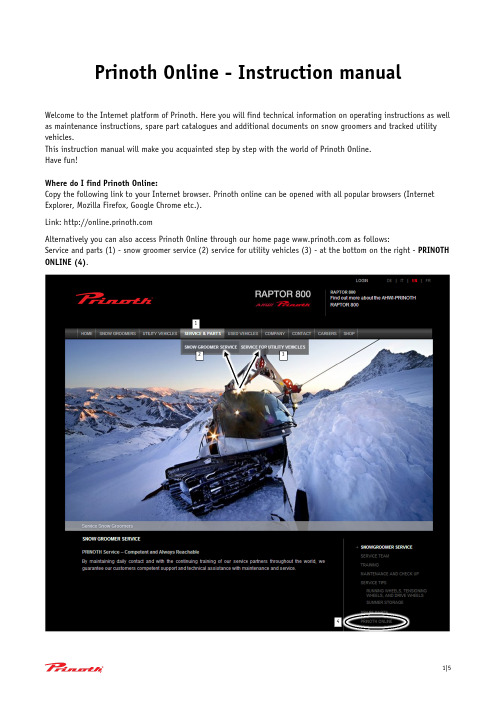
Prinoth Online - Instruction manualWelcome to the Internet platform of Prinoth. Here you will find technical information on operating instructions as well as maintenance instructions, spare part catalogues and additional documents on snow groomers and tracked utility vehicles.This instruction manual will make you acquainted step by step with the world of Prinoth Online.Have fun!Where do I find Prinoth Online:Copy the following link to your Internet browser. Prinoth online can be opened with all popular browsers (Internet Explorer, Mozilla Firefox, Google Chrome etc.).Link: Alternatively you can also access Prinoth Online through our home page as follows:Service and parts (1) - snow groomer service (2) service for utility vehicles (3) - at the bottom on the right - PRINOTH ONLINE (4).12 34If you have a password for Prinoth Online and your account has already been activated, you can skip the chapter on registration.Registration:You will find the registration application on the right side.Please fill out the fields with your information (such as first name and surname,email address, country, etc.).In addition you must let us know on what products you need information. Multipleselections are possible and welcome.Finally, please agree to the General Terms and Conditions of Business and then clickon SEND APPLICATION.If the registration button appears grey, it means that a box was incorrectly filled inor not filled in at all.If the button remains white, all required fields have been filled in and theapplication can be sent off.If some fields have been filled in incorrectly (e.g. password is too short), this will beindicated in a corresponding dialog box. Correct the required fields if necessary andsubmit the application again.Wait a few seconds until confirmation of the submitted application appears.After the application has been checked by Prinoth employees, you will automatically receive an email with your confirmation registration. From then on you can use Prinoth Online.Language selection:If you would like to access the Web site in another language, you can selected it on the right upper side. In addition to German, English, Italian and French are also available.Logging in:Please enter your email address and your password.Then click on login.In case you have entered your email address or your password incorrectly and/or you have not registered yet, an error message appears.Click on OK and check your entry and/or fill out the application registration.If all data has been entered correctly, all functions of your Prinoth Online account are available after a few seconds. A dialogue box confirms the successful registration.How to use Prinoth Online:1 Your name appears here;2 By clicking on the "log off" button you can log off from Prinoth Online;3 Language selection: one can switch between German, English, Italian and French;4 Search field / search function;5Processes - here the desired section can be selected. The operating instructions, spare parts catalogue and in the case of certain machines the repair and maintenance manual may be selected, multiple selections as well as a single selection are possible;6 Products - here the products selected by you are listed. You can select the desired product by clicking on it, multiple selections or single selection are possible;7Year - here specific years can be selected; multiple selections as well as single selection are possible;Sorting and searching of data:By clicking the date (1) or the title (2) in the block above data can be sorted; Similarly you can do a search by entering the title in the search box (3);2134567 1 23Opening and/or downloading data:When you have found the desired data, click on the text (1) and the field (2) will appear grey. At the same time a window opens at the bottom edge of the screen (3).By clicking on the symbol - in this case a PDF symbol (4) - the data can be opened or saved on the right side of the page (6).The same happens if one selects highlight text (5) in the field below.Data can only be opened and/or downloaded separately.In case data is not available in the desired language, the English version will be shown.We wish you a lot of fun with Prinoth Online. Your Customer Service Team1235 46。
RFduino产品数据手册说明书

Tel: 949.610.0008Approved & CertifiedRF ModuleDATASHEETShrunk an Arduino to the size of a finger-tipand made it Wireless!RFduino is a Bluetooth 4.0 Low Energy BLE RF Modulewith Built-In ARM Cortex M0 Microcontroller for Rapid Development and Prototyping ProjectsSimple to use Arduino IDE and sketches running on professional grade hardwareRFD22121 USB Shield RFD22122 RGB LED / Button Shield RFD22123 S ervo Shield RFD22124 PCB USB Shield RFD22125 Proto Shield An RFduino "Shield" is a modular accessory that directly plugs into the RFduino.RFD22126 D ual AAA Battery ShieldRFD22127 Single AAA Battery Shield RFD22128 CR2032 Battery Shield RFD22130 MicroSD Shield RFD22131 Dual Relay Shield RFD22102 RFduino DIPStackable & plugs directly into breadboards RFD22102 RFduino DIP Based On RFD22301 RF Digital RF Module RFD90101, RFD90102, RFD90103, RFD90104, RFD90105 Eval / Dev KitsTel: 949.610.0008Approved & CertifiedRF ModuleDescriptionMin Max NotesVDD - Supply Voltage2.1 V3.6 V General Purpose I/O (GPIO) input high voltage0.7 * VDD VDD General Purpose I/O (GPIO) input low voltage VSS 0.3 * VDD Output standard drive current Output high drive currentMax 3 pinsULP Current with RC OSC RunningTransmit Current Receive Current ARM CPU Running Current Dimensions:X: 0.900" (22.86mm) Y: 1.140" (28.95mm)Z: 0.725" (18.4mm) RFD22121 USB Programmer (Included in dev kits)Tel: 949.610.0008Approved & CertifiedRF ModuleTel: 949.610.0008Approved & Certified RF ModuleThe links below direct to the App Store, where you can download the 4 sample apps to your iOS device (i.e. iPad / iPhone). Temperature App:https:///us/app/rfduino-temperature/id668832196?mt=8Color Wheel App:https:///us/app/rfduino-colorwheel/id685753295?mt=8Approved & Certified RF ModuleTel: 949.610.0008Dimensions:X: 0.900" (22.86mm)Y: 1.514" (38.46mm)Z: 0.725" (18.4mm)RFD22122 RGB LED / Pushbutton ShieldThe RFD22122 RGB LED / Pushbutton shield plugs onto the RFduino. It has 2 button inputs with 10k resistor pull downs and it also has an RGB LED with series LEDs.Dimensions:X: 0.900" (22.86mm)Y: 0.920" (23.37mm)Z: 0.725" (18.4mm)Approved & Certified RF ModuleTel: 949.610.0008Dimensions:X: 0.900" (22.86mm)Y: 1.400" (35.56mm)Z: 0.725" (18.4mm)RFD22124 PCB USB ShieldThe RFD22124 PCB USB shield is the exact same item as the RFD22121 USB shield shown above, except it does not have a formed metal USB connector, it instead uses a PCB type USB connector.Dimensions:X: 0.900" (22.86mm)Y: 1.384" (35.15mm)Z: 0.725" (18.4mm)Approved & Certified RF ModuleTel: 949.610.0008Dimensions:X: 0.900" (22.86mm)Y: 0.900" (22.86mm)Z: 0.722" (18.34mm)RFD22126 Dual AAA Battery ShieldThe RFD22126 Dual AAA Battery shield, requires two AAA batteries. It has a step-up regulator that is set to supply 3.3V output, even when the AAA batteries drop in voltage as they run down over time.Dimensions:X: 1.000" (25.54mm)Y: 3.050" (77.47mm)Z: 0.900" (22.86mm)Tel: 949.610.0008Approved & CertifiedRF ModuleADimensions:X: 0.900" (22.86mm)Y: 2.980" (75.69mm) Z: 0.922" (23.42mm)The RFD22128 CR2032 Coin Battery shield, requires one CR2032 3V battery.RFD22128 CR2032 Coin Battery Shield Dimensions:X: 0.900" (22.86mm) Y: 1.850" (46.99mm) Z: 0.720" (18.3mm)Approved & Certified RF ModuleTel: 949.610.0008Dimensions:X: 0.900" (22.86mm)Y: 0.910"(23.11mm)Z: 0.725" (18.4mmRFD22131 Dual Relay ShieldThe RFD22131 Dual Relay shield provides two SPDT, independently controlled relays.Dimensions:X: 0.900" (22.86mm)Y: 1.400" (35.56mm)Z: 0.775" (19.69mm)Approved & Certified RF ModuleTel: 949.610.0008RFD90103 RFduino Dev KitApproved & Certified RF ModuleTel: 949.610.0008CE, ETSI, IC, FCC Compliance InformationThe RFD22301 is IC and FCC Modular Approved and Certified for Canada and USA, therefore for use of the RFD22301 module in your product does not require further IC or FCC testing for an intentional radiator for compliance of the RFD22301. Detail instructions and IC and FCC notices shown later in this data sheet. Any modifications made to the RFD22301 will void the IC and FCC Approval and Certification. The RFD22301 has an integrated on-board chip antenna. You simply include the RFD22301 in your product and follow the IC and FCC notices and information below and place the appropriate label on your product to indicate that it includes an IC and FCC approved module and no further testing would be required for the module.The RFD22301 is CE (ETSI) Tested. See declaration of conformity later in this document.Tel: 949.610.0008Approved & CertifiedRF ModuleCE, ETSI, IC, FCC Approved & CertifiedSee RFD22301 datasheet at: /RFD22301RFD22301 RFduino SMT version is ideal for ultra small size applications and its perfect for Here is the wiring diagram for the RFD22301 RFduino SMT Module for connecting to theRFD22121 USB programming (shield) dongle. The RFD22102 RFduino DIP directly plugsinto the RFD22121 USB programming module. The RFD22301compliance approved SMT module is placed onto a DIP board to create the RFD22102RFduino DIP form factor.Plugs directly into breadboardsTel: 949.610.0008Approved & CertifiedRF ModuleIndustry Canada InformationThis device complies with Industry Canada licence-exempt RSS standard(s). Operation is subject to the following two conditions: (1) this device may not cause interference, and (2) this device must accept any interference, including interference that may cause undesired operation of the device.Le présent appareil est conforme aux CNR d'Industrie Canada applicables aux appareils radio exempts de licence. L'exploitation est autorisée aux deux conditions suivantes : (1) l'appareil ne doit pas produire de brouillage, et (2) l'utilisateur de l'appareil doit accepter tout brouillage radioélectrique subi, même si le brouillage est susceptible d'en compromettre le fonctionnement.IC LABELRelating to Model Number R25 (RFD Part Number: RFD22301)The unit should have a permanently attached label in a conspicuous location with the following statement:NOTES:1. Industry Canada does not specify the size of the label or the lettering thereon. The only requirement is that the text be legible.Approved & Certified RF ModuleTel: 949.610.0008SAMPLE FCC STATEMENT TO BE INCLUDED IN USER'S MANUAL Relating to Model Number R25 (RFD Part Number: RFD22301) INSTRUCTION TO THE USER (if device DOES NOT contain a digital device)The user is cautioned that changes or modifications not expressly approved by the party responsible for compliance could void the user’s authorit y to operate this equipment.INSTRUCTION TO THE USER (if device contains a digital device)This equipment has been tested and found to comply with the limits for a class B digital device, pursuant to part 15 of the FCC Rules. These limits are designed to provide reasonable protection against harmful interference in a residential installation. This equipment generates, uses and can radiate radio frequency energy and if not installed and used in accordance with the instructions, may cause harmful interference to radio communications. However, there is no guarantee that interference will not occur in a particular installation. If this equipment does cause harmful interference to radio or television reception, which can be determined by turning the equipment off and on, the user is encouraged to try to correct the interference by one or more of the following measures:* Reorient or relocate the receiving antenna.* Increase the separation between the equipment and receiver.* Connect the equipment into an outlet on a circuit different from that to which the receiver is connected.* Consult the dealer or an experienced radio/TV technician for help.In order to maintain compliance with FCC regulations, shielded cables must be used with this equipment. Operation with non-approved equipment or unshielded cables is likely to result in interference to radio and TV reception. The user is cautioned that changes and modifications made to the equipment without the approval of manufacturer could void the user's authority to operate this equipment.Approved & Certified RF ModuleTel: 949.610.0008FCC LABELRelating to Model Number R25 (RFD Part Number: RFD22301)The unit should have a permanently attached label in a conspicuous location with the following statement:NOTES:1. The FCC does not specify the size of the label or the lettering thereon. The only requirement is that the text be legible.2. If the entire label can not be placed on the unit due to space constraint, only FCC ID may be displayed on the unit. In such cases, the compliance statement will have to be included in the "user’s manual". NOTE: Device must be smaller than a man’s palm.** If the unit also interfaces with phone line, it requires additional information on the label - refer to part 68 information **Approved & Certified RF ModuleTel: 949.610.0008RoHSDeclaration Of ConformityNovember 17, 2013RF Digital declares that part numbers• RFD22301• RFD22102• RFD22121• RFD22122• RFD22123• RFD22124• RFD22125• RFD22126• RFD22127• RFD22128• RFD22130• RFD22131are manufactured with RoHS materials.RF Digital Corporation1601 Pacific Coast Highway, Suite 290Hermosa Beach, CA 90254Approved & Certified RF ModuleTel: 949.610.0008DECLARATION OF CONFORMITYNovember 17, 2013RF Digital declares that part numbers• RFD22301 (Model Number R25)• RFD22102comply with ETSI EN 300 440-2 power requirementsas called out in the R&TTE V1.2.1 DirectiveTechnical documents for the above mentioned part numbers are held atRF Digital Corporation1601 Pacific Coast Highway, Suite 290Hermosa Beach, CA 90254Approved & Certified RF ModuleTel: 949.610.0008Important NoticeRFduino is being manufactured by RF Digital Corp. (hereafter referred to as RF Digital).RF Digital reserves the right to make corrections, modifications, and/or improvements to the productand/or its specifications at any time without notice.RF Digital assumes no liability for the user’s product and/or applications.RF Digital products are not authorized for use in safety-critical applications, including but not limited to life-support applications.RF Digital assumes no liability for parts or their application beyond replacement or refunding the original purchase price.All trademarks and trade names belong to their respective owners.Information provided in this document is for reference only. The user must conduct testing and prototyping on their own for their own application. This document only provides an example of a possible use for the parts shown in this design and requires actual testing to confirm its accuracy or validity or proper application. There is NO suggestion that the devices shown in this document should be used for the implied application. There is no guarantee or warranty of suitability for any specific application. The information disclosed in this document is AS-IS. By using any information contained in this document you are assuming all risks and liability associated therewith. RF Digital reserves the right to make corrections, modifications, changes and/or improvements to specifications or details at any time without notice or obligation. RF Digital assumes no liability for the user’s product and/or applications. RF Digital products are not authorized for use in safety-critical applications, including but not limited to life-support applications. RF Digital assumes no liability for parts or their application beyond replacement or refunding the original purchase price paid to RF Digital.Limited Product WarrantyRF Digital warrants that RF Devices manufactured by RF Digital are free from defects in material and workmanship, for Ninety (90) Days from date of delivery. RF Devices covered by this warranty and returned to RF Digital within the Ninety Day Warranty Period will be eligible for replacement, repair, or credit, limited to the amount RF Digital was paid for the RF Device. To obtain a remedy under this Warranty, the following conditions must be met: (1) Customer must notify RF Digital in writing promptly on discovery of the deficiency with reasonable detail within the Warranty Period; (2) Customer must return the RF Devices to RF Digital promptly upon receipt of an RMA f rom RF Digital, at Customer’s risk and expense; and (3) RF Digital confirms the claimed deficiency is present. If all of these conditions are met, RF Digital, at its sole option, will either replace or repair the RF Device or credit Customer’s account for the amount the Customer paid to RF Digital for the RF Device.End of document.。
- 1、下载文档前请自行甄别文档内容的完整性,平台不提供额外的编辑、内容补充、找答案等附加服务。
- 2、"仅部分预览"的文档,不可在线预览部分如存在完整性等问题,可反馈申请退款(可完整预览的文档不适用该条件!)。
- 3、如文档侵犯您的权益,请联系客服反馈,我们会尽快为您处理(人工客服工作时间:9:00-18:30)。
Smartphone Pentest Framework v0.1User GuideIntroduction:The Smartphone Pentest Framework (SPF) is an open source tool designed to allow users to assess the security posture of the smartphones deployed in an environment. The tool allows for assessment of remote vulnerabilities, client side attacks, social engineering attacks, post exploitation and local privilege escalation. This is an initial release, with a subset of features from each section. SPF is the product of DARPA Cyber Fast Track grant.SPF is made up of several parts that may be mixed and matched to meet users' needs. SPF v0.1 includes the following:•SPF Console•SPF Web based GUI•SPF Android App•SPF Android AgentSPF Console:The console is a text based Perl program that allows SPF users to perform all the server functionality of SPF.SPF GUI:The GUI is a web based front end for SPF that allows users to perform all the server functionality. It is a set of Perl based webpages.SPF Android App:The SPF Android App allows users to use the mobile modem of the Android smartphone with SPF to send SMS messages, gather information, etc. Users can also perform server functionality directly from Android smartphones using this app.SPF Android Agent:The SPF Android Agent is one of SPF's post exploitation options. It is transparent to the user and allows SPF users to perform post exploitation tasks such as privilege escalation, information gathering, and remote control on Android phones with the agent installed. Agents for iPhone and Blackberry platforms are currently in development.Prerequisites:WebserverMysql databasePerlPerl packages:Bundle::ExpectDBD::MYSQLWebserver Perl support (required by the SPF GUI)Android smartphone (required by the SPF Android app)Android development environment (if modification of agents and app to meet users' custom needs is desired)Installation:SPF is currently supported on the Linux operating system. Support for Windows and Mac is a near term planned feature.Installing Prerequisites:Perl is probably already present on your system. If not type apt-get install perl (or platform equivalent) at the command line. Two dependencies for the SPF console (Expect and Mysql) are not met in the base install. Expect installs easily Linux systems using Perl's CPAN tool.perl -MCPAN -e 'install Bundle::Expect'The syntax to install Mysql is:perl -MCPAN -e 'install DBD::mysql'however this is prone to errors and may fail.apt-get install libdbd-mysql-perl (or your platforms equivalent)is a better solution.A Mysql database server is required by SPF. The database server need not be on the same physical machine if so desired. SPF will use a database called “framework.” Details about the Mysql server will be read by SPF from its config file, so keep those handy.A webserver is required by SPF. The webserver does need to be on the same physically machine as the SPF console and/GUI at this time. The webserver will require Perl support to use the SPF GUI. Webserver Perl support is not required to exclusively use the console.If you are having trouble installing the prerequisites, XAMPP includes both the necessary Mysql server and webserver (including Perl support).Installing SPF Console:The SPF console is packaged as frameworkconsole.C hange the permissions on all the files with chmod 777 * in theframework console directory. Make changes to the config file (discussed later in this section), and you are ready to go.Installing SPF GUI:The SPF GUI is packaged as frameworkgui. Copy it to the webserver ro ot.Then change the permissions on all the files withchmod 777 * in the framework console directory. Make changes to the config file (discussed later in this section), and you are ready to go.Installing SPF Android App:The full source code of the SPF Android App as well as an APK is available in FrameworkAndroidApp. To make changes to the source code, open upthe project in your Android development environment. To have the Framework Android App catch SMS based responses from a deployed agent (discussed later in this document), open the SMSReceiver.java file and change the values of key and controlnumber to the control key and phone number of the deployed agent respectively. Compile the APK and install it on the desired smartphone. All other variables will be set during setup.Config File:SPF GUI and SPF console include an identical text based config file. This file tells SPF important information such as the location and login information of the Mysql server, location of the webserver, etc. At the current time the config file reads as follows:#SMARTPHONE PENTEST FRAMEWORK CONFIG FILE#ROOT DIRECTORY FOR THE WEBSERVER THAT WILL HOST OUR FILES WEBSERVER = /opt/lampp/htdocs#IPADDRESS TO LISTEN ONIPADDRESS = 192.168.0.108#IP ADDRESS OF SQLSERVER 127.0.0.1 IF LOCALHOSTMYSQLSERVER = 192.168.0.107#USERNAME OF THE MYSQL USER TO USEMYSQLUSER = root#PASSWORD OF THE MYSQL USER TO USEMYSQLPASS = password#PORT MYSQL IS RUNNING ON (3306 IS DEFAULT)MYSQLPORT = 3306#LOCATION OF ANDROID APK FOR AGENT DROPANDROIDAGENT = /root/AndroidAgent.apk#LOCATION OF IPHONE DEB FOR AGENT DROPIPHONEAGENT = /root/iphone.debChange any values necessary to match your own environment. It SPF console or GUI fails a bad configuration option is the most likely culprit.Using the SPF Console:To start the SPF console type ./framework.pl.Creating or Clearing the Database:If it is your first time using SPF, the first thing to do is set up the database. If things just get too complicated and you want to start over, using this option is also a good idea. However, be forewarned that this will destroy all your data and detach all modems, agents, apps, etc.To clear/create the database choose option 7. You will be warned that this will destroy all your data. Type y to agree to this. All tables in the framework database will be dropped if they exist and recreated with no data.Attaching to an Android AppCurrently the Android app is the only way to connect a mobile modem to SPF. Support for USB mobile modems and Google Voice is currently in development. In order to use the mobile network to send attacks, communicate with deployed agents, etc. you will need to deploy the SPF Android app on an Android smartphone (any Android phone with a mobile modem and Android version 1.6 and above works, so burn phones are acceptable). The SPF console will use the modem on the Android device to communicate over the mobile network. To attach to an SPF Android app choose option 4. Choose option 2 to connect to a smartphone based app (option 1 for an attached mobile modem is still in development). You will be asked to supply the phone number of the smartphone where the app is installed, a path on the webserver to host control files, and the 7 digit key that will be used to control the app. Fill in this data and then choose y if the data is correct.The SPF console will appear to hang. It is waiting for a SPF app to connect. Open the SPF Android app. You will be asked to fill in the IP address of the webserver, the control key, and the path on the webserver to the control files. Make sure that the key and path are the same as you entered in the SPF console.Click Setup and both the app and the console will return to the menu screens.Remote Attacks:SPF allows you to run remote attacks against smartphone platforms, via HTTP or SMS. To run a remote attack choose option 2. In version 0.1 a remote attack is implemented to check for the default SSH password (“alpine”) on jailbroken iPhones. Select option 1. You will be prompted for the IP address to test. Enter this value and type y when asked if this is correct.Three things may happen, either there will be no SSH server present at the IP address given in which case the SSH connection will time out, there will be an SSH server but its password will not be the default, in which case the login will fail, or the iPhone will be vulnerable. If the iPhone is vulnerable, SPF will log in and install the iPhone agent (currently a stub). Successes and failures will be recorded in the database.Client-Side and Social Engineering Attacks:SPF allows you to create and host malicious webpages, PDFs etc. to launch client side attacks against smartphone platforms. Additionally, SPF tests smartphone users' susceptibility to SMS based social engineering attacks. To launch such attacks select option 6.Two attacks are currently implemented in this category. The first one is a social engineering attack that sends an SMS to a smartphone and requests that they download and install a “cool app.” The app will of course be an SPF agent. To launch this attack select option 1. You will be prompted for the webserver path to host the app, the filename, the smartphone platform, and the phone number to attack.Using this data SPF will host the agent for the selected platform on the webserver at the path specified (this is currently only useful for Android victims as the iPhone and Blackberry agents are still in development). If more than one mobile modem is currently attached to SPF you will be prompted to choose which modem you would like to use to send the SMS. An SMS is then sent to the phone number provided with a link to download the app.The other currently implemented option is an attack against the mobile browser on Android (CVE-2010-1759 Webkit). Instead of selecting option 1 for direct download, select option 2. You will be prompted for the hosting path, file name, and phone number to attack. A malicious page that attempts to exploit the vulnerability is crafted and hosted on the webserver. A socket listening for a remote connection from an exploited is started. If more than one mobile modem is currently attached to SPF you will be prompted to choose which modem you would like to use to send the SMS. An SMS is then sent to the phone number provided with a link to a “coolpage.” If the smartphone user opens the link in the mobile browser, the page will attempt to exploit the Webkit vulnerability. If it is successful, the smartphone will connect to the listening socket. SPF will run a command on the exploited smartphone, close the connection, and record the results. Keeping a shell open for SPF user interaction is a planned feature. If the user does not click on the link or the browser is not vulnerable the socket will timeout.Attach to a Deployed Agent:You can attach SPF to a manually deployed agent. This basically just adds it to the database so you can interact with it using SPF. Choose option 1 at the main menu. You will be asked for information about the agent including the phone number, control phone number (modem used to receive results via the mobile network), platform, 7 digit control key, and HTTP control URL. Most of this is currently hardcoded in the agent itself, so just make sure it matches.Send Commands to Agents:By choosing option 2 at the main menu you can send commands to agents installed on remote smartphones. The command currently supported are:1)Send SMS2)Take Picture3)Get Contacts4)Get SMS Database5)Privilege EscalationAll commands may be delivered to agents via SMS or HTTP. Some commands return data while others do not. Of those that return data, you will be prompted to choose between SMS and HTTP for the return method if both are available. You will first be asked to select an agent to interact with. Currently only Android agents are available, but iPhone and Blackberry agents are in production.The Send SMS function allows you to send an SMS to another phone using the mobile modem from the agent infected smartphone.Take picture takes a picture if possible and uploads it to the webserver.Get Contacts and Get SMS Database return the contacts and the last 10 SMSs received by the agent infected smartphone.Privilege Escalation attempts to root the infected smartphone. Currently this functionality attempts to use the rageagainstthecage exploit against Android phones. If successful it will return that it worked and then drop the root privileges. Further use of root privileges is in development.View Data Gathered from Agents:Use option 3 to see the results of agent commands that return data. You will be prompted to choose an agent.Using the SPF GUIThe SPF GUI includes all the same functionality as the SPF console. As its name suggests it is graphical rather than text based. If you have not already done so, edit the config file in the SPF GUI folder to suit your environment. Browse to http://localhost/menu.plFor information about the functionality see the SPF console section. The functionality is identical here. However, instead of choosing menu options we use text boxes, radio buttons, etc. Functionality is performed in the background only, whereas from the console, some functionality may be performed in the foreground. After functionality is run, the page refreshes and the database is queried for the most up to date data.Using the SPF Android AppTo attach the SPF Android app to a SPF console or GUI server, use the process described in the SPF console section. After attachment, you will be taken to the functionality menu. Additionally, the mobile modem of the device can now be used by SPF for communication.From the SPF Android app you can perform a subset of the functionality available in SPF console and SPF GUI. For instance you cannot recreate the database inside of the app, as that would detach the app. The functionality usage is the same as in SPF GUI and console except in the app it looks a little different of course.Also all agent commands default to SMS delivery and SMS return if available using the mobile modem in the app's host smartphone. To detach the app, just use the back button until you reach the attachment screen you saw when you first started the app.Building Agents:Deploying agents is currently not a very simple process. Variable for the agents are hardcoded, so you will need to edit the source code (provided) and recompile them using you Android development environment. Particularly the control key, the path, and the control IP are hardcoded in AndroidAgent.java and the control key and control phone number are hardcoded in SMSReceiver.java. Change these values to fit your needs and build the agents using your Android development environment. Cleaning up this process and the ability to build custom agents from inside SPF is in development.。