康海时代(COMHIGHER)NC601mb的产品技术参数
康海时代(COMHIGHER)NC601的产品技术参数
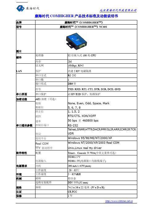
50 bps至460800 bps
控制台端口
RS-232
软件特性
协议
Telnet,SNMP,HTTP,DHCP,PPP/SLIP,ARP,ICMP,IP,TCP, UDP,
使用平台
Windows 95/98/ME/NT/2000/XP
Real COM
Windows NT/2000/XP/2003 Real COM
TTY驱动程序
Unix,Linux real tty driver
配置
Telnet,Console和Web(中英文菜单可选)
电源需求
电源输入
NC601:5 V
NC601-5V(电源接口为接线端子)
功耗
290 mA/1.45W(max)
环境
工作温度
-20~85℃
工作湿度
5~95%RH
机械
材料
铝合金
规格
康海时代COMHIGHER产品技术标准及功能说明书
品牌
康海时代™(COMHIGHER™)
型号
康海时代™(COMHIGHER™)NC601
图片
硬件
处理器
32位嵌入式100兆CPU
ቤተ መጻሕፍቲ ባይዱ内存
2M
LAN
以太网
10Mbps, RJ45
保护
内建2 KV电磁隔离
串口界面
串口方式
RS-232
串口数
1
接口形式
DB9针
信号
TXD, RXD, RTS, CTS, DTR, DSR, DCD, GND
串口保护
15 KV ESD保护,短路保护
加密功能
AES加密(可选)
串口通讯参数
康海时代NC900产品说明书

康海时代NC900 系列串口服务器康海时代NC900串口服务器是一种面向高端客户开发的串口联网通讯的产品,通过它用户可以在Internet中的任意位置访问串口终端,实现串口设备数据传输应用扩展功能。
康海时代采用真实双网口设计,有两个独立ip地址,可以支持两个网段的主机对设备进行管理,数据通讯等。
康海时代NC900支持多种应用模式,其中支持TCP 服务器模式,TCP客户端模式,UDP模式,对联模式,反向终端模式,允许用户软件通过标准网络应用程序接口(winsock BSD sockets)访问串口设备,支持实串口模式的COM、TTY驱动,传统应用软件采用com口通讯,无需做任何改动,这些产品特性能够保护用户软件低成本投资的同时,还能为用户提供更灵活的应用环境。
康海时代NC900支持动态主机配置协议(DHCP),用户可以通过网页浏览器或者telnet方式快速配置IP地址,另外用户也可以使用产品配套的windows管理软件(ComHigher Utility)快速管理串口服务器,还能实时对串口服务器运行状态进行管理和检测。
康海时代NC900串口服务器设计融合多种创新,真正成为串口服务器行业中的高端品牌。
NC900系列串口通讯服务器NC900系列串口服务器选型指南NC901系列NC901ANC901DNC901BNC902系列NC902NC902-2MDNC902+NC908系列NC908NC908-8MDNC916系列NC916NC916-16MNC932系列NC932NC932-32MNC901系列串口服务器特点提供2个10/100M 自适应网口,并且支持MDI,MDI-X 自适应功能 单串口服务器采用ARM9 平台,嵌入式LINUX 操作系统,性能稳定可靠 提供丰富的工作模式实现串口设备立即联网功能 支持Real Com/TTY 驱动,完全兼容原有应用软件具有TCP Server 、TCP Client 和UDP 等通用透明传输模式 支持串口服务器直接对联模式和反向终端模式 可通过网页浏览器或TELNET 终端进行配置管理 附带Windows 平台下的管理软件,提供强大管理功能可自由选择串口类型每个串口带有15KV ESD浪涌保护串口通信速率最高可达460.8KbpsRJ45(Female)线序管脚定义技术参数RS-232 RS-422/485 RS-232/422/485软件操作模式Real Port,TCP server, TCP client, UDP, Pair Slave/Master,Reverse Telnet操作系统Windows 98/ME/NT/2000/XP/2003/Win 7NC902系列串口服务器特点提供2个10/100M自适应网口,并且支持MDI,MDI-X自适应功能2口串口服务器采用ARM9 平台,嵌入式LINUX操作系统,性能稳定可靠提供丰富的工作模式实现串口设备立即联网功能支持Real Com/TTY驱动,完全兼容原有软件系统具有TCP Server、TCP Client和UDP等通用透明传输模式支持串口服务器直接对联模式和反向终端模式可通过网页浏览器或TELNET终端进行配置管理附带Windows平台下的管理软件,提供强大管理功能可自由选择串口类型每个串口带有15KV ESD浪涌保护串口通信速率最高可达460.8Kbps技术参数RS-232RS-422/485RS-232/422/485软件操作模式Real Port,TCP server, TCP client, UDP, Pair Slave/Master, Reverse Telnet操作系统Windows 98/ME/NT/2000/XP/2003/Win7NC908系列串口服务器特点8口机架式串口服务器提供2个10/100M自适应网口,并且支持MDI,MDI-X自适应功能采用ARM9 平台,嵌入式LINUX操作系统,性能稳定可靠提供丰富的工作模式实现串口设备立即联网功能支持Real Com/TTY驱动,完全兼容原有应用软件具有TCP Server、TCP Client和UDP等通用透明传输模式支持串口服务器直接对联模式和反向终端模式可通过网页浏览器或Telnet终端进行配置管理附带Windows平台下的管理软件,提供强大管理功能可自由选择串口类型每个串口带有15KV ESD浪涌保护串口通信速率最高可达460.8Kbps尺寸RJ45串口线序管脚定义技术参数RS-232RS-422/485软件操作系统Windows 98/ME/NT/2000/XP/2003/Win7配置方式Web browser, Telnet Console ,Windows UtilityNC916系列串口服务器特点16口机架式串口服务器提供2个10/100M自适应网口,并且支持MDI,MDI-X自适应功能采用ARM9 平台,嵌入式LINUX操作系统,性能稳定可靠提供丰富的工作模式实现串口设备立即联网功能支持Real Com/TTY驱动,完全兼容原有应用软件具有TCP Server、TCP Client和UDP等通用透明传输模式支持串口服务器直接对联模式和反向终端模式可通过网页浏览器或Telnet终端进行配置管理附带Windows平台下的管理软件,提供强大管理功能可自由选择串口类型每个串口带有15KV ESD浪涌保护串口通信速率最高可达460.8Kbps尺寸RJ45 串口线序管脚定义技术参数协议DHCP、Telnet、TCP、UDP、IP、SMTP操作模式Real Port,TCP server, TCP client, UDP, Pair Slave/Master, Reverse TelnetNC932系列串口服务器特点32口机架式串口服务器提供2个10/100M自适应网口,并且支持MDI,MDI-X自适应功能采用ARM9 平台,嵌入式LINUX操作系统,性能稳定可靠提供丰富的工作模式实现串口设备立即联网功能支持Real Com/TTY驱动,完全兼容原有应用软件具有TCP Server、TCP Client和UDP等通用透明传输模式支持串口服务器直接对联模式和反向终端模式可通过网页浏览器或Telnet终端进行配置管理附带Windows平台下的管理软件,提供强大管理功能可自由选择串口类型每个串口带有15KV ESD浪涌保护串口通信速率最高可达460.8Kbps尺寸RJ45 串口线序管脚定义技术参数RS-232RS-422/485接口速率10/100M支持MDI,MDI-X自适应功能网口保护2KV 隔离保护。
NC601系列产品说明书

北京浦特伟业科技有限公司 地 址:北京市昌平区黄平路 19 号院龙旗广场 2 号楼 816 室 电 话:82666020/88840664/8266055 传 真:010-82669890 EMAIL:sales@ 24 小时服务热线:13911070077
1
北京浦特伟业科技有限公司
目录
一.NC601 系列串口服务器简介 ..................................................................................................................... 4 1.1 概述 .................................................................................................................................................... 4 1.2 产品特性: ......................................................................................................................................... 5 1.3 硬件规格和尺寸: .............................................................................................................................. 5 1.4 硬件安装: ......................................................................................................................................... 6
康海时代32口串口服务器
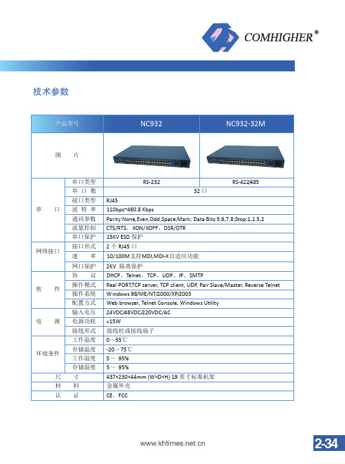
2KV 隔离保护
DHCP、Telnet、TCP、UDP、IP、SMTP
Real PORT,TCP server, TCP client, UDP, Pair Slave/Master, Reverse Telnet
Windows 98/ME/NT/2000/XP/2003
Web browser, Telnet Console, Windows Utility
RS-422/485
32 口
RJ45
110bps~460.8 Kbps
Parity:None,Even,Odd,Space,Mark; Data Bits:5,6,7,8;Stop:1,1.5,2
CTS/RTS,XON/XOFF,DSR/DTR
15KV ESD 保护
2 个 RJ45 口
10/100M支持MDI,MDI-X自适应功能
技术参数
产品型号
NC932
NC932-32M
图片
串口
网络接口
软件
电源
环境条件 尺 材 认
串口类型 串口数 接口类型 波特率 通讯参数 流量控制 串口保护 接口形式 速率 网口保护 协议 操作模式 操作系统 配置方式 输入电压 电源功耗 接线形式 工作温度 存储温度 工作湿度 存储湿度 寸 料 证
RS-232
24VDC/48VDC/220VDC/AC
<15W
接线柱或接线端子
0~55℃
-20~75℃
5~ 95%
5~ 95%
437×230×44mm (W×D×H) 19 英寸标准机架Biblioteka 金属外壳CE、FCC
2-34
NC600使用手册

/入配置文件 导出 导出/
用upgrade 程序搜索到设备以后,并且确保能ping通此设备,可选择[Tools]->[Upload device setting]导出配置文件
选择保存配置文件的路径,并且命名配置文件
导入配置文件 搜索到需要导入配置文件的设备,并确保能ping通此设备,选择[Tools]->[Download device setting]
查找设备后能列出[Server Name] 、 [ServerPosition] 、 [Ports]、 [IPAddress] 、 [MACAddress]、 [Firmware Version] 、[Password]. 常常搜索到的 IP 地址和主机地址不在同一个网段,可以点击[Tools]�[Temporary change IP address]
2.网页配置方式 直接在 IE 浏览器的地址栏中输入 NC600 的 IP 地址,就可以进入 IE 配置界面,在 IE 中每一步 的修改必须点击”提交”,修改完成之后必须”保存设置”并”重启设备 电 地 网 话:010-88861339 传 真 :010-88865076 址:北京市海淀区中关村永丰产业基地永丰路 5 号院 4 号楼 401A 站:
在弹出的对话框中输入想要的 IP 地址:
点击[OK] 注: 临时修改 IP 地址后未重启设备之前生效,重启设备也就是断电后会恢复到之前的 IP 地址, 如果需要永久修改 IP,应该到设备的配置界面修改 ,如:通过”telnet +ip”的方式进入配置界面 , 按方向键移动光标到[服务器],在[服务器]中可以永久修改 IP 地址,改完 IP 后到[综合]中保存 设置,并且重启设备.
电 地 网
话:010-88861339 传 真 :010-88865076 址:北京市海淀区中关村永丰产业基地永丰路 5 号院 4 号楼 401A 站:
NC601系列快速安装手册1

第1页第2页第3页NC601系列通讯服务器快速安装手册2011年8月第二版1概述康海时代NC601系列IO-Server 是具有1个10/100M 以太网口和1个异步串口的通讯服务器。
串口类型是RS232/RS422/RS485三合一的。
2产品包装和配件清单在您打开产品包装后,请核对包装盒中的物品是否符合下列清单标准配置:■1台NC601系列通讯服务器■1个5V 电源适配器■1张快速安装手册■1张存有相关软件和说明文档的光盘3硬件简介产品外观4硬件安装步骤①安装产品:打开包装,将设备以桌面式安装②连接电源之前:a.将电源以及设备的线路分开。
如果电源的线路以及设备的线路可能交叉重迭,确认线路在交叉点上是垂直的。
b.备注:不要将通讯的线路与电源的线路绑在一起。
为了避免信号互相干扰,不同特性的电子信号应该分开。
c.如果必要的话,建议您贴上线路卷标于所有的设备上。
③连接电源:a、如果您采用产品附带的电源适配器,请将其一端插在220v 交流电源插座上,另一端插接在NC301系列通讯服务器的电源接口上b、如果您采用自己的电源:将电源正极连接在标有“+5V”的端子上,负极连接在标有“GND”的端子上注意:1、电源要求:电压的波动范围在4.9V~5.4V,最大输出电流为1A2、请仔细阅读本说明,电源线接反可能会对产品造成损坏④连接网络:连接网线的一端到NC601系列通讯服务器的网口,另一端连接到以太网络。
⑤连接设备:用串口电缆将NC601的串口与串口设备的串口连接起来5进入NC601系系列串口服务器的设置界面①查找NC601系列串口服务器②程序会显示所有的在线的NC601,并显示出其IP,NC601默认出厂IP为:192.168.0.233③点击设置按钮,进入界面设置IP地址等参数。
康海时代NC600产品说明书

COMHIGHER康海时代NC600使用说明书COMHIGHER康海时代NC600系列使用说明书目录:1、COMHIGHER串口服务器简介 (2)1.1概述 (2)1.2产品特性 (2)1.3硬件规格及硬件连接 (3)1.3.1硬件规格 (3)1.3.2硬件连接 (4)2、工作模式说明 (5)2.1TCP Realport模式 (5)2.2TCP服务端模式 (5)2.3TCP客户端模式 (6)2.4UDP模式 (6)3Web控制台 (6)3.1介绍 (6)3.2登录 (7)3.3主菜单 (7)3.4串口配置 (8)3.5工作模式 (9)3.5.1Real Port实串口模式 (9)3.5.2TCP/UDP SOCKET模式 (10)3.6用户管理 (11) (11)3.7、状态监测 (12) (12)3.8出厂设置 (12)3.16重启 (13)4、windows下软件控制台 (14)4、1介绍 (14)4.2主界面 (14)4.3初始化IP地址 (14)4.4.固件升级 (15)5、虚拟串口 (16)附录A (17)串口管脚定义和线缆线序 (17)附录B、 (19)常见问题解答 (19)附录C: (20)产品选型 (20)1、COMHIGHER串口服务器简介1.1概述COMHIGHER NC600系列串口服务器是一种用于扩展串行设备通信应用的产品,通过它用户可以很容易通过局域网或Internet中的任意位置访问现有串行设备(如工控设备、POS终端、读卡器、支付终端、监控设备等),实现串行设备数据传输应用扩展功能。
COMHIGHER NC600系列串口服务器支持多种应用模式,其中TCP服务端模式、TCP客户端模式、UDP模式等工作模式,允许用户软件通过标准网络应用程序接口(Winsock、BSD Sockets)访问串行设备。
另外,实串口模式的COM驱动支持原有COM应用软件无需任何更改地通过TCP/IP网络访问串行设备。
Arcom 产品说明书

PCIB4040-Ch Digital I/O & Counter BoardTechnical ManualContentsRevision . . . . . . . . . . . . . . . . . . . . . . . . . . . . . . . . . . . . . . . . . . . . . . . . . . . . . . . . . . . . . . . . . . . . . . . .2 Preface: . . . . . . . . . . . . . . . . . . . . . . . . . . . . . . . . . . . . . . . . . . . . . . . . . . . . . . . . . . . . . . . . . . . . . . . . .2 Packing list . . . . . . . . . . . . . . . . . . . . . . . . . . . . . . . . . . . . . . . . . . . . . . . . . . . . . . . . . . . . . . . . .2 Utility Disk . . . . . . . . . . . . . . . . . . . . . . . . . . . . . . . . . . . . . . . . . . . . . . . . . . . . . . . . . . . . . . . . . .2 Handling (ESD/Packaging) . . . . . . . . . . . . . . . . . . . . . . . . . . . . . . . . . . . . . . . . . . . . . . . . . . . . .2 Contacting Arcom . . . . . . . . . . . . . . . . . . . . . . . . . . . . . . . . . . . . . . . . . . . . . . . . . . . . . . . . . . . . . . . . .2 Introduction . . . . . . . . . . . . . . . . . . . . . . . . . . . . . . . . . . . . . . . . . . . . . . . . . . . . . . . . . . . . . . . . . . . . . .3 Features . . . . . . . . . . . . . . . . . . . . . . . . . . . . . . . . . . . . . . . . . . . . . . . . . . . . . . . . . . . . . . . . . . .3 Getting Started . . . . . . . . . . . . . . . . . . . . . . . . . . . . . . . . . . . . . . . . . . . . . . . . . . . . . . . . . . . . . .3 Operation . . . . . . . . . . . . . . . . . . . . . . . . . . . . . . . . . . . . . . . . . . . . . . . . . . . . . . . . . . . . . . . . . . . . . . . .4 I/O Map . . . . . . . . . . . . . . . . . . . . . . . . . . . . . . . . . . . . . . . . . . . . . . . . . . . . . . . . . . . . . . . . . . .5 I/O Function Registers . . . . . . . . . . . . . . . . . . . . . . . . . . . . . . . . . . . . . . . . . . . . . . . . . . . . . . . .5 Special Function Registers . . . . . . . . . . . . . . . . . . . . . . . . . . . . . . . . . . . . . . . . . . . . . . . . . . . . .6 Links . . . . . . . . . . . . . . . . . . . . . . . . . . . . . . . . . . . . . . . . . . . . . . . . . . . . . . . . . . . . . . . . . . . . . . . . . . .7 Default Link Position Diagram . . . . . . . . . . . . . . . . . . . . . . . . . . . . . . . . . . . . . . . . . . . . . . . . . . .7 Base Address Select . . . . . . . . . . . . . . . . . . . . . . . . . . . . . . . . . . . . . . . . . . . . . . . . . . . . . . . . . .7 Power-up Output/State Control . . . . . . . . . . . . . . . . . . . . . . . . . . . . . . . . . . . . . . . . . . . . . . . . . .8 Counter 0 Clock Frequency Select . . . . . . . . . . . . . . . . . . . . . . . . . . . . . . . . . . . . . . . . . . . . . . .8 Counter 1 and 2 Output Select . . . . . . . . . . . . . . . . . . . . . . . . . . . . . . . . . . . . . . . . . . . . . . . . . .9 User Configuration Record Diagram . . . . . . . . . . . . . . . . . . . . . . . . . . . . . . . . . . . . . . . . . . . . . .9 Connectors . . . . . . . . . . . . . . . . . . . . . . . . . . . . . . . . . . . . . . . . . . . . . . . . . . . . . . . . . . . . . . . . . . . . . .10 Installation for CE Compliance . . . . . . . . . . . . . . . . . . . . . . . . . . . . . . . . . . . . . . . . . . . . . . . . . . . . . . .11 Cable . . . . . . . . . . . . . . . . . . . . . . . . . . . . . . . . . . . . . . . . . . . . . . . . . . . . . . . . . . . . . . . . . . . . .11 Circuit Diagrams . . . . . . . . . . . . . . . . . . . . . . . . . . . . . . . . . . . . . . . . . . . . . . . . . . . . . . . . . . . . . . . . . .12PrefacePacking ListThis product is shipped as follows:• Board• User Manual • Utility Disk• PCbus Library DatasheetIf any of the above appear to be missing, please telephone Arcom 01223 411200.Utility DiskThis product is shipped with a utility disk which contains:• PCbus library Manual• Source Code for all PCbus I/O boards • A test program called TEXT.EXEHandlingThis board contains CMOS devices which could be damaged in the event of static electricity being discharged through them. At all times please observe anti-static precautions when handling the board and always unpack and install the board in an anti-static working area.Please ensure that should a board need to be returned to Arcom, it is adequately packed and if a battery is fitted, that it is isolated.Product InformationFull information about other Arcom Products is available via the Fax on Demand System , (Telephone Numbers are listed below), or by contacting our WebSite in the UK at: , or in the US at:Useful Contact InformationSales:Tel: +44 (0)1223 411 200Customer Support:Tel: +44 (0)1223 412 428Fax: +44 (0)1223 410 457Fax: +44 (0) 1223 403 400E-Mail:**************.ukE-Mail:****************.ukE-Mail:**************************United KingdomArcom Control Systems Ltd Clifton Road Cambridge CB1 4WH. UKTel: +44 (0)1223 411200Fax: +44 (0)1223 410457FoD: 01223 240 600United StatesArcom Control Systems Inc 13510 South Oak StreetKansas City MO 64145, USA Tel: 888 941 2224Fax: 826 941 7807FoD: 800 747 1097FranceArcom Control Systems Centre d’affaires SCALDY 23, rue Colbert78885 SAINT QUENTIN Cedex, FRANCE Tel: 0800 90 84 06Fax: 0800 90 84 12FoD: 0800 90 23 80GermanyKostenlose Infoline:Tel: 0130 824 511Fax: 0130 824 512FoD: 0130 860 449BelgiumGroen Nummer:Tel: 0800 7 3192Fax: 0800 7 3191ItalyNumeroVerde:FoD: 1678 73600NetherlandsGratis 06 Nummer:Tel: 06022 11 36Fax: 06022 11 48IntroductionThe PCIB40 is an 8-bit ISA bus add-on board providing 40 channels of digital I/O and three 16-bitcounter/timers. The digital I/O is organised into 5 groups of 8 bits. Each I/O channel may beconfigured as an input or an output. The board also includes the facility to define the power-up/reset state of a group of output bits. This is extremely useful in ensuring the safe start-up of aPC-controlled system. The 3 counter/timers are implemented using the industry-standard 8254device. One timer can be used as a periodic interrupt generator while the other two timers can beconnected to external signals for frequency measurement and pulse generation.The D-50 I/O connector conforms to Arcom’s standard Signal Conditioning System (SCS) and maybe used to drive a range of Signal Conditioning Boards (SCB); see Arcom’s PCbus catalogue formore details.Features• CE compliant design• 40-channel digital I/O• Three 16-bit counter/timers with max count rate (input and output) 1MHz• Compact I/O addressing scheme (link selectable base address)• Link-selectable interrupt options (IRQ2,3,4,5,7)• Each channel has a current sink capability of **********and source current of 500µA @ 2.7V• Bit programmable for input or output• Group selection of powerup/reset state.• Board access LED (for all decoded addresses)• User controlled LED• 8-bit bus interface• I/O connector conforms to Arcom Signal Conditioning System (SCS)• Operating temperature range, +5°C to +55°C• Power consumption from the host, max 300mA @ +5V• MTBF: 477,000 hours (using generic figures from MIL-HDBK-217F at ground benign) Getting Started• Switch off PC• Install Board in supplied configuration• Switch on PC• Run TEST.EXE (supplied on utility disk)• An access/user LED should flash. If not check default link configuration. (Page 7)OperationReading or Writing to the BoardControl of the PCIB40 is achieved by writing to a pointer register and then accessing a dataregister to read or write the required I/O register. The pointer register need only be written with anew value if a different register is to be accessed. The board occupies only two bytes of PCbusI/O space. Each time the board is accessed, the red LED will flash momentarily.Digital I/O channelsTo use a digital channel (or bit) as an output simply write to that channel (or bit). To use a digitalchannel (or bit) as an input write a ‘1’ to the channel to initialise . Thereafter a read can be used.You can configure each digital channel (or bit) as an input or an output but it is advisable toconfigure the board in groups. e.g. Group 1,2 & 3 output, Group 4 & 5 input. When an output is setto ‘0’ (logic low) it is not advisable to attempt to drive the external connection to logic high.Reading a digital channel, when it is an output, will return the state of the output. This can be usefulif you need to check the status of an output.Electrical configuration of each digital channel:Power-up or reset state of outputsWhen digital I/O boards are used to control large or crucial items of plant, it is often necessary todefine how the output lines power-up. This is because it can take many seconds to boot anoperating System and run an application program from reset and begin initialising the system.Each group of eight I/O signals can be selected to be a logical ‘0’, a logical ‘1’ or ‘don’t care’ atpower-up or on reset. This is configured using jumpers (see links section).To use this feature set the links for the power-up or reset condition required. Then in your codewrite to the group registers the output levels required, and finally enable the outputs by writing a‘1’ to bit 0 of register 90 (hex).Note:This feature is suited to outputs not inputs. Setting an input to a power-up state of ‘0’ willrequire the group register being written with all ‘1’s’ to enable the use of the channels as inputs.Counter TimersThe PCIB40 includes three programmable 16-bit counter/timers. Counter 0 may be driven by eithera 10KHz, 100KHz or 1MHz clock and can be used to generate regular interrupts. An interrupt isgenerated only when the counter 0 output goes to a ‘1’.The input and gate control signals of counters 1 and 2 are connected as inputs from the D-50 whilethe counter outputs are linkable to the D-50 connector. Counter inputs 1 and 2 may be used forfrequency or pulse measurement and the outputs used for pulse generation. Refer to the linksection and pin assignments table for connection details.I/O mapThe value written to the pointer register is used to select the on-board I/O location to be accessed.This board occupies two consecutive addresses and has nine I/O function registers and threespecial function registers.The board must be set on an even address boundary. (i.e. 180h, 182h, 200h etc.)I/O Function Registers* A copy of the 8254 (71054) data sheet may be obtained from our Customer Support team (Tel: 01223 412 428)Special Function RegistersThe green User LED is controlled by bit 0 when the pointer register is loaded with 80h.The board identification register can be used to confirm that the board is present in the system and is the correct board type. Other PCbus I/O boards in Arcom’s range will return a different value.LinksThroughout this section a ‘+’ indicates a default link.Default Link Position DiagramK A 2K A 3K A 4K A 5K A 6K A 7K A 8K A 9K A 1Base Address SelectLinks LKA1-9The base address of the PCIB40 is set using the link area shown below:Note:When a link is fitted the address line is decoded as a ‘1’ and when the link is omitted the address line is decoded as a ‘0’.The default address is set to 180hThe clock input for counter 0 can be connected to an on-board clock generator operating at either 10KHz, 100KHz or 1MHz. This is set using LK1A/B/C.Links 10-14 Power-Up Output StateThese links are used to select the power-up state of the five groups of I/O channels. For more information see page 4.Links 20-24 Power-up controlSelect whether the output buffer is always enabled or controlled by software. If you are configuring the board for known boot up state then the group must be software enabled. If link B is fitted the output state cannot be determined (‘don’t care’ state) at power up or reset.Link IRQ2-5 & 7 Interrupt selectThe output of counter 0 can be used to generate an interrupt on either IRQ 2,3,4,5 or 7. NOTE:A PC must be configured with only one interrupt source for each interrupt line. Check your PC configuration before selecting the interrupt signal. If you are not using the interrupt facility, it is recommended that the jumper is not fitted.+The outputs from counter 1 and 2 can be connected to the D-50 connector using LK4 and 3respectively.NOTE:The counter outputs are interfaced to the I/O connector using an inverting open-collector driver. The output state is therefore the inverse of the counter output state defined in the data sheet. When using the counter outputs, it is necessary to ensure that the I/O signals for group 2,bits 0 and 1, are set for input mode by writing ‘1’s to both bits. This avoids the counter output conflicting with the I/O port output. User Configuration Record DiagramLK23LK24LK14L K A 2L K A 3L K A 4L K A 5L K A 6L K A 7L K A 8L K A 9L K A 1LK13LK22LK12LK21LK11LK20LK10A B A B A B A B A B A B A B A B A B A BL K 1CL K 1ALK1BLK3LK4IRQ2IRQ3IRQ7IRQ4IRQ5D-50 Output Connector (PL2) Pin AssignmentsThe pin assignments are listed with the pin number of the D-50 connector and also the pin number when a 50-way IDC ribbon cable is connected to the D-50. The pin assignments conform to the Arcom Signal Conditioning System (SCS) and may be connected to an external Signal Conditioning Board.Installation for CE ComplianceTo maintain compliance with the requirements of the EMC Directive (89/336/EEC), this productmust be correctly installed. The PC in which the board is housed must be CE compliant asdeclared by the PC manufacturer. The type of external I/O cable can be chosen according to thenotes below:1. Remove the cover of the PC observing any additional instructions of the PC manufacturer2. Locate the board in a spare ISA slot and press gently but firmly into place3. Ensure that the metal bracket attached to the board is fully seated4. Fit the bracket clamping screw and firmly tighten this on the bracketNOTE: Good contact of the bracket to chassis is essential5. Replace the cover of the PC observing any additional instructions of the PC manufacturerCableCable length 1Metre or less :Ribbon cable satisfactoryCable length 1M to 3M:Commercial screened cable gives the protection requiredLonger cable or noisy environment :Use fully screened cable with metal backshellse.g. Arcom CAB50CEThe following standards have been applied to this product:BS EN50081-1: 1992 Generic Emissions Standard, Residential, Commercial, Light IndustryBS EN50082-1: 1992 Generic Immunity Standard, Residential, Commercial, Light IndustryBS EN55022 : 1995 ITE Emissions, Class B, Limits and MethodsCircuit Diagrams。
- 1、下载文档前请自行甄别文档内容的完整性,平台不提供额外的编辑、内容补充、找答案等附加服务。
- 2、"仅部分预览"的文档,不可在线预览部分如存在完整性等问题,可反馈申请退款(可完整预览的文档不适用该条件!)。
- 3、如文档侵犯您的权益,请联系客服反馈,我们会尽快为您处理(人工客服工作时间:9:00-18:30)。
品牌
康海时代™(COMHIGHER™)
型号
康海时代™(COMHIGHER™)NC601mb
图片
硬件
处理器
32位嵌入式100兆CPU
内存
2M
LAN
以太网
10M
保护
内建2 KV电磁隔离
串口界面
串口通讯参数
串口方式
TTL信号
串口数
1
接口形式
24针的双排插针
Windows NT/2000/XP/2003 Real COM
TTY驱动程序
Unix,Linux real tty driver
配置
Telnet,Console和Web(中英文菜单可选)
电源输入
5 V
环境
功耗
290 mA/1.45W(max)
工作温度
-20~85℃
机械
工作湿度
5~95%RH
材料
铝合金
1, 1.5, 2
流控
RTS/CTSห้องสมุดไป่ตู้ XON/XOFF
速率
50 bps至460800 bps
控制台端口
RS-232
协议
Telnet,SNMP,HTTP,DHCP,PPP/SLIP,ARP,ICMP,IP,TCP, UDP,
电源需求
使用平台
Windows 95/98/ME/NT/2000/XP
Real COM
规格
选购安装配件
DIN导轨(35 mm)
认证
体积
50.4x 28.2毫米(W x D)
CE,FCC
保修
1年
信号
RS-232:TXD, RXD, RTS, CTS, DTR, DSR, DCD, GND
RS-422:Txd+,Txd-,Rxd+,Rxd-,GND.
RS-485:Data+,Data-,GND
校验
None, Even, Odd, Space, Mark
软件特性
数据位
5, 6, 7, 8
停止位