Gambit中写风机tur文件的步骤
Gambit使用说明(中文版一系列)4GAMBIT菜单命令
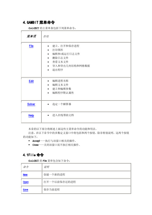
4.GAMBIT菜单命令本章的以下部分将阐述上面这些主菜单命令的功能和用法。
注意,在以下章节中的多数定义窗口中将包括和两个按钮。
除非特别说明,这两个按钮的功能如下:Accept——执行与该窗口相关的操作。
Close——关闭该窗口而不执行相关操作。
4.1File命令4.1.1 New当用户从File菜单中选择了New,GAMBIT打开Create New Session窗口。
Create New Session窗口允许用户建立和命名一个新进程。
要创建一个新的进程,用户必须指定如下项目:进程标识保存选项另外,除了上述两项,GAMBIT也允许用户设定进程的标题。
进程标识包含与该新进程相关联的GAMBIT数据文件的基本名称。
(有关数据文件的内容和格式的说明,请参阅本向导的第二章。
)保存选项决定GAMBIT在建立新进程之前是否保存现有进程的数据。
进程标题包含了该进程的一般说明。
定义进程标识进程标识可以由任意的字母组合和/或GAMBIT所运行的系统环境下允许的有效文件名中所包含的符号组成。
GAMBIT默认的进程标识为"model1"。
设定保存选项当用户建立一个新进程时,将删除与当前进程相关的所有数据。
为了在建立新的进程之前保存当前进程的相关数据,必须选中Create New Session窗口中的Save current session选项。
设定进程标题进程标题包含该进程的一般描述。
他可以由长度不超过80个字符的任意字母组合和/或符号组合而成。
运用Create New Session窗口Create New Session窗口(如下图)使用户可以创建一个新的GAMBIT进程。
要打开Create New Session窗口,只要从主菜单条的File菜单中选择New即可。
窗口中包括以下详细说明:ID:设定新进程的标识Title:设定新进程的标题,长度不超过80字符Save current session 设定在创建新进程时保存当前进程的所有数据。
GAMBIT操作方法、Fluent操作方法
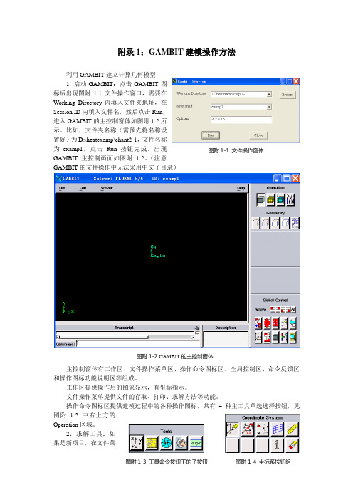
附录1:GAMBIT 建模操作方法利用GAMBIT 建立计算几何模型1. 启动GAMBIT :点击GAMBIT 图标后出现图附1-1文件操作窗口,需要在Working Directory 内填入文件夹地址,在Session ID 内填入文件名,然后点击Run ,进入GAMBIT 的主控制窗体如图附1-2所示。
比如,文件夹名称(需预先将名称设置好)为D:\heatexamp\chant2-1,文件名称为examp1,点击Run 按钮完成。
出现GAMBIT 主控制画面如图附1-2。
(注意GAMBIT 的文件操作中无法采用中文子目录) 主控制窗体有工作区、文件操作菜单区、操作命令图标区、全局控制区、命令反馈区和操作图标功能说明区等组成。
工作区提供操作后的图象显示,有坐标指示。
文件操作菜单提供文件的存取、打印、求解方法等功能。
操作命令图标区提供建模过程中的各种操作图标,共有4种主工具单选选择按钮,见图附1-2中右上方的Operation 区域。
2.求解工具:如果是新项目,在文件菜单区点击Solver ,确定求解工具为FLUENT5/6。
3. 建模坐标系统:选择工具命令按钮(Tools Command Buttoen ),确定所建模型的坐标系统,有5个可选项目,见图附1-3。
其中第一个按钮为坐标系选择按钮,选取该钮后,出现图附1-4所示坐标系统按钮组,其默认按钮为第一个,在该按钮下出现图附1-5的坐标系创建窗户。
在Type 栏中有三种选择,分别是直角坐标、柱坐标和球坐标系统。
对于创建二维直角坐标,直接点击按钮,其二维坐标创建窗户见图附1-6。
在默认条件下可以逐步输入XY 平面上几何坐标系统X 和Y 的最大值、最小值及相临两条网格线之间的间隔值,用Update 钮确定。
注意在Options 栏目中的Snap 选项取选中。
为几何建模确定坐标位置的基准图。
例:创建一个x 方向为8,y 方向为1的区域,其操作过程如下: 在图附1-6中按顺序选定Visibility 项(为红色),Plane 项中XY 单选按钮(为红色)。
各种格式的模型与gambit接口教程
各种格式的模型与gambit接口教程1.ProE实体倒入:在proe中export成step文件,之后在gambit中import注:ProE中点选保存副本图标,选择以STL格式保存副本。
参见附图。
注意,实体必须画在几何空间中第一象限。
(即实体上所有点的X、Y、Z坐标都为正)附件为一个可用的STL格式文件,你可以试试导入GAMBIT。
2. UG和PRO/E中的风机import到gambit中Ug或pro/e中生成了几何模型可以以很多种形式导入gambit,如step igs stl等。
3如何将cad导入到gambit中在AutoCAD中输出的sat格式文件,到了gambit里面输入时出错--ACIS error 3205:save file is from a later version of ACIS我用的是cad2004,这条出错信息搞得我一头雾水既然出错有编号3205,我可以在帮助文件里看到它的详细解释吗?A:file-->import-->acis...存sat格式的较低版,如8。
0版,11。
0版gambit不认识你可以采用较低的AutoCAD版本A:可以使用igs模式导入A:(1)Gambit只适用于创建简单的三维几何体,对于复杂形体而言,其绘图功能是远远不够的,这时Gambit允许我们引入一些其他软件创建的文件,常用的有Autocad创建的ASCI 形式的文件.sat。
CAD中创建的图形要输出为.sat文件,要满足一定的条件。
对于二维图形来说,它必须是一个region,也就是说要求是一个联通域。
对于三维图形而言,要求其是一个ASCI body。
(2)先把autoCAD对象构成实体,导出.sat文件,再在gambit导入,注意有版本高低问题4 fluent中的cas文件能变成gambit里的dbs文件Q:在我现在想将cas文件中的网格做修改,该怎么办?A:可以,import进来就能得到5.怎么在ansys中制作模型导入fluent?A:存成一个gambit可以识别的格式。
Gambit与Fluent的操作过程
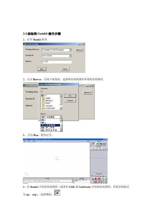
2.4插装阀Gambit操作步骤
1、打开Gambit软件
2、点击Browse,出现下面情况,选择所绘制的图形所要保存的路径。
3、点击Run,软件打开。
4、在Gambit中绘制仿真图形(或者在CAD或Solidworks中绘制仿真图形,其保存的格式为igs、step)。
选择图标:
5、对所画的仿真图形进行网格化。
选择图标:
6、设置网格化好的图形的边界条件,选择图标:
7、保存设置好的图形文件,其格式为msh。
出现如下所示,(如是二维选中export2-D(X-Y)Mesh) 选择Accept。
8、选择EXIT退出Gambit。
选择YES
1、打开FLUENT软件
2、导入前处理器Gambit中网格化的仿真图形。
3、检查有没有最小体积有没有负体积。
(如出现负体积在迭代计算中会出错)
4、在FLUENT中默认状态下的单位是m(米),单位的转换。
5、流动液体的密度、动力粘度及边进出口压力或流动液体的速度的设置等。
、
6、对置的参数进行初始化,进行迭代计算。
7、迭代计算后的插装阀内部流场的压力云图、速度云图、速度矢量图。
GAMBIT操作方法、Fluent操作方法
附录1:GAMBIT 建模操作方法利用GAMBIT 建立计算几何模型1. 启动GAMBIT :点击GAMBIT 图标后出现图附1-1文件操作窗口,需要在Working Directory 内填入文件夹地址,在Session ID 内填入文件名,然后点击Run ,进入GAMBIT 的主控制窗体如图附1-2所示。
比如,文件夹名称(需预先将名称设置好)为D:\heatexamp\chant2-1,文件名称为examp1,点击Run 按钮完成。
出现GAMBIT 主控制画面如图附1-2。
(注意GAMBIT 的文件操作中无法采用中文子目录) 主控制窗体有工作区、文件操作菜单区、操作命令图标区、全局控制区、命令反馈区和操作图标功能说明区等组成。
工作区提供操作后的图象显示,有坐标指示。
文件操作菜单提供文件的存取、打印、求解方法等功能。
操作命令图标区提供建模过程中的各种操作图标,共有4种主工具单选选择按钮,见图附1-2中右上方的Operation 区域。
2.求解工具:如果是新项目,在文件菜单区点击Solver ,确定求解工具为FLUENT5/6。
3. 建模坐标系统:选择工具命令按钮(Tools Command Buttoen ),确定所建模型的坐标系统,有5个可选项目,见图附1-3。
其中第一个按钮为坐标系选择按钮,选取该钮后,出现图附1-4所示坐标系统按钮组,其默认按钮为第一个,在该按钮下出现图附1-5的坐标系创建窗户。
在Type 栏中有三种选择,分别是直角坐标、柱坐标和球坐标系统。
对于创建二维直角坐标,直接点击按钮,其二维坐标创建窗户见图附1-6。
在默认条件下可以逐步输入XY 平面上几何坐标系统X 和Y 的最大值、最小值及相临两条网格线之间的间隔值,用Update 钮确定。
注意在Options 栏目中的Snap 选项取选中。
为几何建模确定坐标位置的基准图。
例:创建一个x 方向为8,y 方向为1的区域,其操作过程如下: 在图附1-6中按顺序选定Visibility 项(为红色),Plane 项中XY 单选按钮(为红色)。
Fluent风机计算教程

离心风机数值计算教程西北工业大学航海学院编制1. 流场建模蜗壳部分流场建模(1)草绘蜗壳轮廓(2)拉伸草图,绘制流域(3)扣除叶轮部分(4)增加风机出口叶轮流场建模(1)拉伸草图(2)扣除叶轮电机和进风口(3)扣除叶片和叶轮盘(4)静态线框图保存(1)建立的三维模型需要保存成iges 、step或X-T等三维模型通用格式,便于导入CFD前处理软件。
2.CFD前处理Gambit软件介绍快捷键功能鼠标左键旋转鼠标中键平移鼠标右键缩放Shift+鼠标左键选中Shift+鼠标中键框选、反向、替换换当先选中项Shift+鼠标右键确定(相当于点击Apply按钮)(2)各按钮功能简要介绍几何体操作按钮,激活后第二排分别为点、线、面、体和几何组按钮,分别激活可以进一步操作。
网格划分操作按钮,激活后第二排分别为边界层网格、边网格、面网格、体网格和几何组网格按钮,分别激活可以进一步操作。
边界条件设置操作按钮,激活后第二排分别为边界边界条件设置(进出口设置)和区域类型设置(定区域、静区域设置)按钮,分别激活可以进一步操作。
常用工具操作按钮,激活后第二排分别为坐标系设置、函数法生成网格、轴流叶轮工具等,分别激活可以进一步操作。
对于该模型,没有使用这一项。
功能按钮区,常用的有:适应窗口大小、调整显示坐标方向、隐藏几何体、转换静态线框模型和和实体模型、撤销和重做以及网格质量统计等功能。
文件导入(1)打开Fluent前处理软件Gambit ,分别导入蜗壳和叶轮部分的step文件和。
File→Import→STEP...(2)先导入叶轮部分,再导入蜗壳部分(3)全部导入后发现建模时,叶轮和蜗壳的坐标系不统一,二者位置关系不正确。
此时需要将蜗壳部分相对于xoy平面翻转180度。
(4)以实体图显示:(5)将叶轮部分两端凹进部分补齐,分别作为叶轮进口。
此操作主要目的是产生A、B两环面,并将这两个换面定义为wall类型,可以模拟风机进口处的挡风环。
gamit 操作步骤

gamit 操作步骤
以下是Gamit软件的操作步骤:
1. 数据准备:准备GPS观测数据和相关的参考桩,确保数据的准确性和完整性,并将其存储在计算机上的合适位置。
2. 数据导入:打开Gamit软件,从菜单中选择“数据导入”选项,在弹出的对话框中,选择准备好的GPS观测数据文件,并导入到Gamit中。
3. 固定点选择:根据需要选择一些固定点,这些点的坐标已知且稳定。
这些固定点将用于基线解算和数据校正。
请注意,以上步骤仅适用于Gamit软件的基本操作,如果您需要更详细的信息或操作指南,建议参考Gamit软件的官方文档或相关教程。
gambit轴流风机网格划分
BASIC TURBO MODEL WITH UNSTRUCTURED MESH8. BASIC TURBO MODEL WITH UNSTRUCTURED MESH This tutorial employs a simple turbine blade configuration to illustrate the basic turbo modeling functionality available in GAMBIT. It illustrates the steps and procedures required for importing data that describes the turbo blade, creating a geometric model that describes the flow region surrounding the blade, meshing the model, and exporting the mesh. The example presented here uses 3-D boundary layers to control the shape of the mesh in the regions immediately adjacent to the blade and employs an unstructured hexa-hedral mesh.In this tutorial, you will learn how to:•Import a turbo data file•Create a turbo profile•Modify a turbo profile to affect the shape of a turbo volume•Create a turbo volume•Define turbo zones•Apply 3-D boundary layers to a turbo volume•Mesh a turbo volume•View a turbo volume mesh using both 3-D and 2-D perspectives•Export a turbo volume mesh8.1 PrerequisitesPrior to reading and performing the steps outlined in this tutorial, you should familiarize yourself with the steps, principles, and procedures described in Tutorials 1, 2, 3, and 4.© Fluent Inc., Mar-06 8-1Problem Description BASIC TURBO MODEL WITH UNSTRUCTURED MESH8-2 © Fluent Inc., Mar-068.2 Problem DescriptionFigure 8-1 shows the turbomachinery configuration to be modeled and meshed in this tutorial. The configuration consists of a turbine rotor on which are affixed 60 identical blades, each of which is spaced equidistant from the others on the rotor hub. Each blade includes a concave (pressure ) side and a convex (suction ) side, and the rotor rotates counterclockwise about the x -axis, extracting work from the fluid (air) as it flows betweenthe blades (see Figure 8-2).Figure 8-1: 60-blade turbine rotorBASIC TURBO MODEL WITH UNSTRUCTURED MESH Problem DescriptionOutlet flowInlet flowFigure 8-2: Turbine rotor blade configurationsThe overall goal of this tutorial is to create a geometric model of the flow region immedi-ately surrounding one of the turbo blades and to mesh the model using an unstructured hexahedral mesh.© Fluent Inc., Mar-06 8-3Strategy BASIC TURBO MODEL WITH UNSTRUCTURED MESH8.3 StrategyIn general, the GAMBIT turbo modeling procedure includes seven basic steps:1)Creating or importing edge data that describes the turbo profile2)Creating the turbo profile3)Creating the turbo volume4)Assigning zone types to regions of the turbo volume5)Decomposing the turbo volume6)Meshing the turbo volume7)Viewing the turbo volumeThis tutorial illustrates six of the seven steps listed above. The tutorial excludes the turbo decomposition step, because the turbo volume is to be meshed using unstructured hexahe-dral mesh elements. Turbo volume decomposition is primarily used to facilitate the crea-tion of structured meshes (see Tutorial 9 in this guide).NOTE: In this tutorial, the turbo-volume viewing operation (Step 7, above) is illustrated in conjunction with the mesh examination step (see “Step 11:Examine the Mesh,” below). 8-4 © Fluent Inc., Mar-06BASIC TURBO MODEL WITH UNSTRUCTURED MESH Procedure 8.4 Procedure1.Copy the filepath/Fluent.Inc/gambit2.x/help/tutfiles/turbo_basic.tur (where 2.x is the GAMBIT version number) from the GAMBIT installation area in the directory path to your working directory.2.Start GAMBIT using the session identifier “Basic_Turbo”.Step 1: Select a Solver1.Choose the solver from the main menu bar:Solver → FLUENT 5/6The choice of solver affects the types of options available in the Specify Boundary Types form (see “Step 12:Specify Zone Types,” below). For some systems, FLUENT 5/6 is the default solver. The currently selected solver is shown at the top of the GAMBIT GUI.© Fluent Inc., Mar-06 8-5Procedure BASIC TURBO MODEL WITH UNSTRUCTURED MESH 8-6 © Fluent Inc., Mar-06Step 2: Import a Turbo Data FileTurbo data files contain information that GAMBIT uses to define the turbo profile (see “Step 3:Create the Turbo Profile,” below). Such information includes: point data that describes the shapes of the profile edges, edge-continuity data, and specification of the rotational axis for the turbo volume.1. Select the Import Turbo File option from the main menu bar.File → Import → Turbo...This command sequence opens the Import Turbo Fileform.2. Click the Browse... button.This action opens the Select Fileform.BASIC TURBO MODEL WITH UNSTRUCTURED MESH Procedurea)In the Files list, select turbo_basic.tur.b)On the Select File form, click Accept.3.On the Import Turbo File form, click Accept.GAMBIT reads the information contained in the data file and constructs the set of edges shown in Figure 8-3. The two straight edges shown in the figure describe the hub and casing for the turbo volume. The two sets of curved edges constitute cross sections of a single turbo blade.Casing edgeBlade cross sectionsHub edgeFigure 8-3: Imported turbo geometry© Fluent Inc., Mar-06 8-7Procedure BASIC TURBO MODEL WITH UNSTRUCTURED MESH 8-8 © Fluent Inc., Mar-06Step 3: Create the Turbo ProfileThe turbo profile defines the basic characteristics of the turbo volume, including the shapes of the hub, casing, and periodic (side) surfaces. In GAMBIT , the edges that describe the hub, casing, and blade cross sections are defined by means of their inlet endpoint vertices.1. Specify the hub, casing, and blade-cross-section edges of the turbo profile.TOOLS →TURBO →CREATE PROFILEThis command sequence opens the Create Turbo Profileform.In this step, you will specify vertices that define the hub, casing, and blade cross-sections. In addition, you will specify the axis of revolution for the turbo configu-ration. All instructions listed in this step refer to the vertex labels shown in Figure 8-4.BASIC TURBO MODEL WITH UNSTRUCTURED MESH Procedure© Fluent Inc., Mar-06 8-9 Hub InletCasing InletAB CDBlade TipsFigure 8-4: Vertices used to specify the turbo profilea) Activate the Hub Inlet list box on the Create Turbo Profile form.To activate an input field, such as a list box, on any GAMBIT specification form, left -click in the input box located adjacent to the field label—in this case, “Hub Inlet ”. (By default, GAMBIT activates the Hub Inlet field when you open the Create Turbo Profile form.)b) Select vertex A .c) Activate the Casing Inlet list box.d) Select vertex B .e) Specify the x axis as the axis of revolution for the turbo configuration.i. Click the Axis:Define pushbutton.This action opens the Vector Definition form.Procedure BASIC TURBO MODEL WITH UNSTRUCTURED MESH8-10© Fluent Inc., Mar-06 ii.Select the Direction:X-Positive option.iii.On the Vector Definition form, click Apply.f)Activate the Blade Tips list box.g)Select vertex C.h)Select vertex D.!The order in which the Blade Tips vertices are selected is important to the definition of a turbo profile. Specifically, the Blade Tips vertices must be selected in order from the hub cross section to the casing cross section.i)Click Apply to accept the vertex selections and create the turbo profile.GAMBIT creates the turbo profile shown in Figure 8-5.Rail edgesRail edges Medial edgesABFigure 8-5: Turbo profileThe profile includes six new edges, four of which are real edges and two of which are virtual edges. The four real edges are circular arc (“rail”) edges that are formed by revolving the hub and casing endpoint vertices about the axis of revo-lution for the profile. The two virtual edges are “medial” edges, the centermost shapes of which represent the mean shapes of the blade cross sections. The end-point vertices of the medial edges are hosted by the rail edges, and the medial edges are defined such that they pass through the leading and trailing vertices of the blade cross sections. The medial edges define the shapes of the periodic sur-faces on the turbo volume (see “Step 5:Create the Turbo Volume,” below).© Fluent Inc., Mar-06 8-11Step 4: Modify the Inlet and Outlet Vertex Locations It is often useful to control the shape of the turbo volume such that its inlet and outlet surfaces represent smooth flow transitions to and from the inlet and outlet ends, respectively, of the turbo blade. In GAMBIT, you can control the shape of the turbo volume by adjusting the positions of the medial-edge endpoint vertices prior to con-structing the volume.1.Open the Slide Virtual Vertex form.TOOLS →TURBO →SLIDE VIRTUAL VERTEXThis command sequence opens the Slide Virtual Vertexform.a)Select the inlet endpoint vertex of the medial edge for the casing blade crosssection (vertex A in Figure 8-5, above).b)In the U Value field, enter the value 0.999.As an alternative to entering a value in the U Value field, you can select thevertex in the graphics window and drag it along its host rail edge until the UValue field value is 0.999.c)Retain the Move With Links (default) option.8-12 © Fluent Inc., Mar-06© Fluent Inc., Mar-06 8-13 The Move With Links option specifies that GAMBIT is to apply the current Slide Virtual Vertex specifications to all medial-edge inlet endpoint vertices in addi-tion to the selected vertex.d) Click Apply to accept the new position of the medial-edge inlet endpoint vertices. e) Select the outlet endpoint vertex of the medial edge for the casing blade crosssection (vertex B ).f) In the U Value field, enter the value 0.019.g) Retain the Move With Links (default ) option.h) Click Apply to accept the new position of the medial-edge outlet endpoint vertices.The modified turbo profile appears as shown in Figure 8-6.Figure 8-6: Turbo profile with modified inlet and outlet vertex locationsStep 5: Create the Turbo VolumeA “turbo volume” is a 3-D region—which is defined by a set of one or more geomet-ric volumes—that represents the flow environment surrounding the turbo blade. The turbo volume characteristics are determined by the turbo profile and by specification of the number of blades on the rotor (or angle between blades), the tip clearance, and the number of spanwise sections. This example does not include a tip clearance but does include spanwise sectioning.1.Specify the pitch and number of spanwise sections for the turbo volume.TOOLS →TURBO →CREATE TURBO VOLUMEThis command sequence opens the Create Turbo Volumeform.a)In the Pitch text box, enter 60.b)On the Pitch option button (located to the right of the Pitch text box), select theBlade count option.c)In the Spanwise Sections text box, enter 2.d)Click Apply.GAMBIT creates the turbo volume shown in Figure 8-7.8-14 © Fluent Inc., Mar-06© Fluent Inc., Mar-06 8-15 Casing faceHub faceInletfaces OutletfacesFigure 8-7: Turbo volume—consisting of two geometric volumesStep 6: Define the Turbo ZonesThis step standard zone types to surfaces of the turbo volume. The zone-type specifi-cations determine which faces are linked for meshing. In addition, GAMBIT auto-matically associates turbo zone types to boundary zone definitions for some solvers.1.Specify the faces that constitute the hub, casing, inlet, outlet of the turbo volume, aswell as the pressure and suction sides of the turbo blade.TOOLS →TURBO →DEFINE TURBO ZONESThis command sequence opens the Define Turbo Zonesform.a)Activate the Hub list box.b)Select the bottom (hub) face of the turbo volume (see Figure 8-7, above).c)Activate the Casing list box.d)Select the top (casing) face of the turbo volume.e)Activate the Inlet list box.f)Select the two inlet faces.g)Activate the Outlet list box.h)Select the two outlet faces.8-16 © Fluent Inc., Mar-06i)Activate the Pressure list box.j)Select the six faces on the inner-curve (pressure side) of the turbo blade.k)Activate the Suction list box.l)Select the six faces on the outer-curve (suction side) of the turbo blade.m)Click Apply to assign the turbo zone types.© Fluent Inc., Mar-06 8-17Step 7: Apply 3-D Boundary LayersFor turbo models, 3-D boundary layers allow you to ensure the creation of high-quality mesh elements in regions adjacent to the turbo blade surfaces. Such boundary layers are particularly useful when the turbo volume is to be meshed using an unstructured meshing scheme.1.Specify the hub, casing, and blade-cross-section edges of the turbo profile.TOOLS →TURBO →CREATE/MODIFY BOUNDARY LAYERSThis command sequence opens the Create Boundary Layerform.8-18 © Fluent Inc., Mar-06© Fluent Inc., Mar-06 8-19 a) In the First row text box, enter a value of 1.b) In the Growth factor text box, enter a value of 1.2.c) In the Rows text box, specify a value of 5, either by direct input of the value or bysliding the Rows slider bar.GAMBIT automatically calculates a Depth value of 7.4416, based on the First row , Growth factor , and Rows specifications.d) Select the Internal continuity option.e) In the Attachment input field, select the Faces option.f) Activate the Faces list box, and select the 12 faces that comprise the pressure andsuction sides of the turbo blade.g) Click Apply .Figure 8-8 shows the 3-D boundary layers projected onto the three spanwisesurfaces of the turbo volume.Figure 8-8: Turbo volume with 3-D boundary layersBy default, GAMBIT displays the boundary layers in the graphics window unless they are made invisible by direct user action. The boundary layer dis-play can make it difficult to view the model during subsequent steps in the modeling process; therefore, it is advisable to render the boundary layers invisible before continuing the tutorial.2.Select the SPECIFY DISPLAY ATTRIBUTEScommand button on the GlobalControl toolpad.This action opens the Specify Display Attributesform.a)Select the B. Layers check box.b)Select the Visible:Off option.c)Click Apply.8-20 © Fluent Inc., Mar-06GAMBIT turns off the display of the boundary layers.d)Close the Specify Display Attributes form.© Fluent Inc., Mar-06 8-21Step 8: Mesh the Blade Cross-Section EdgesIn this step, you will pre-mesh the edges that represent the blade cross sections, thereby ensuring a finer mesh in proximity to the turbo blade surfaces than is created in the bulk of the turbo volume.1.Mesh the centermost pressure-side edges of the turbo blade.TOOLS →TURBO →MESH EDGES/FACES/VOLUMESThis command sequence opens the Mesh Edgesform.a)Activate the Edges list box, and select the three centermost edges on the pressureside of the blade cross sections.b)On the Grading:Type option button, retain Successive Ratio.8-22 © Fluent Inc., Mar-06© Fluent Inc., Mar-06 8-23 c) In the Ratio input field, enter a value of 1.02.d) Select the Double sided option.When you select the Double sided option, GAMBIT changes the Ratio input field to Ratio 1 and displays a field named Ratio 2 that contains a ratio specifi-cation identical to that of Ratio 1 (that is, 1.02).e) On the Spacing option button, select Interval count .f) In the Spacing text box, enter a value of 100.g) Click Apply .GAMBIT meshes the selected edges as shown in Figure 8-9. The Double sided option with a ratio of 1.02 grades the edges such that mesh nodes are bunchednear the endpoint vertices of the edges.Figure 8-9: Meshed centermost pressure-side edges of the turbo blade2. Mesh the suction-side edges of the turbo blade.a) Activate the Edges list box, and select the three centermost edges on the suctionside of the blade cross sections.b) On the Grading:Type option button, retain Successive Ratio .c)In the Ratio input field, enter a value of 1.02.d)Select the Double sided option.e)On the Spacing option button, retain Interval count.f)In the Spacing text box, enter a value of 110.g)Click Apply.3.Mesh the leading edges of the turbo blade.a)Activate the Edges list box.b)Select the six edges (two edges on each cross section) on either side of the leadingvertices for the top, middle, and bottom blade cross sections.!When selecting the edges, modify the edge senses, as necessary, such that they point away from the leading vertices of the cross sections. When youselect an edge in the graphics window, GAMBIT automatically displays anarrowhead in the middle of the edge to indicate the sense of the edge. Tochange the sense of any selected edge, Shift-middle-click the edge. (NOTE: Ifthe sense-direction arrowhead is obscured by mesh nodes displayed on theedge, set the Interval count to 1 while selecting edges for meshing.)c)On the Grading:Type option button, retain Successive Ratio.d)In the Ratio input field, enter a value of 1.05.The single-sided meshing option with a ratio of 1.05 grades the edges suchthat mesh nodes are bunched near the leading vertices of the edges—that is, inthe regions of highest curvature for the edges.e)On the Spacing option button, retain Interval count.f)In the Spacing text box, enter a value of 15.g)Click Apply.4.Mesh the trailing edges of the turbo blade.a)Activate the Edges list box.b)Select the six edges (two edges on each cross section) on either side of the trailingvertices for the three blade cross sections.8-24 © Fluent Inc., Mar-06© Fluent Inc., Mar-06 8-25 c) On the Grading:Type option button, retain Successive Ratio .d) In the Ratio input field, enter a value of 1.e) On the Spacing option button, retain Interval count .f) In the Spacing text box, enter a value of 3.g) Click Apply .Figure 8-10 shows the final edge-mesh configuration for the turbo blade crosssections.Figure 8-10: Meshed edges of turbo blade cross sectionsStep 9: Mesh the Center Spanwise FaceTo create an unstructured mesh for this example, it is best to pre-mesh the middle spanwise face and to employ the middle face as a source face for a Cooper meshing scheme applied to the two geometric volumes. The use of the middle face as a source face ensures that the Cooper scheme produces a mesh with minimal distortion throughout the turbo volume.1.Mesh the center spanwise face of the turbo volume.TOOLS →TURBO →MESH EDGES/FACES/VOLUMES RThis command sequence opens the Mesh Faces form.a)Activate the Faces list box, and select the middle spanwise face.GAMBIT automatically selects the Quad and Pave Scheme options based onthe face characteristics.8-26 © Fluent Inc., Mar-06© Fluent Inc., Mar-06 8-27 b) On the Scheme:Elements option button, retain the Quad option.c) On the Scheme:Type option button, retain the Pave option.d) On the Spacing option button, select the Interval size option.e) In the Spacing text box, enter a value of 5.f) Click Apply .GAMBITmeshes the middle spanwise face as shown in Figure 8-11.Figure 8-11: Meshed center spanwise faceStep 10: Mesh the VolumesIn this step, you will apply a Cooper meshing scheme to the two geometric volumes that comprise the turbo volume.1.Mesh the turbo volume.TOOLS →TURBO →MESH EDGES/FACES/VOLUMES RThis command sequence opens the Mesh Volumes form.a)Activate the Volumes list box, and select the both of the geometric volumes thatcomprise the turbo volume.GAMBIT automatically selects the Scheme:Elements:Hex/Wedge and Scheme:Type:Cooper options for the selected volumes.b)Retain the automatically selected Scheme options.c)On the Spacing option button, select Interval size.8-28 © Fluent Inc., Mar-06© Fluent Inc., Mar-06 8-29 d) In the Spacing text box, enter a value of 10.e) Click Apply .GAMBITmeshes the volumes as shown in Figure 8-12.Figure 8-12: Meshed volumesStep 11: Examine the Mesh1.Select the EXAMINE MESHcommand button at the bottom right of the GlobalControl toolpad.This action opens the Examine Meshform.The Examine Mesh form allows you to view various mesh characteristics for the 3-D mesh. For example, Figure 8-13 displays volume mesh elements for which the EquiSize Skew parameter is between 0.4 and 0.5 for this example.a)Click Update at the bottom of the Examine Mesh form.8-30 © Fluent Inc., Mar-06© Fluent Inc., Mar-06 8-31 GAMBIT does not automatically update the graphics display when you open the Examine Mesh form or modify its specifications, such as Display Type or Quality Type . To update the graphics display, you must click the Update push-button located at the bottom of the form. GAMBIT displays the Update pushbutton label in red lettering whenever the display needs to be updated to reflect the current Examine Mesh specifications.Some Examine Mesh operations automatically update the graphics display. For example, if you select the Display Type:Range option and click one of the histogram bars, GAMBITautomatically updates the display.Figure 8-13: Hexahedral mesh elements—EquiSize Skew = 0.4–0.5The Examine Mesh command and options can be used in conjunction with the View Turbo Volume command to view 2-D characteristics of the mesh on the hub, casing, and spanwise surfaces. Such views are particularly useful when examining the mesh on highly twisted blades.2. Display the middle spanwise surface in a cascade turbo view.TOOLS →TURBO →VIEW TURBO VOLUMEThis command sequence opens the View Turbo Volume form.8-32© Fluent Inc., Mar-06a) Select the Cascade surface:Spanwise option.b) In the Spanwise text box, enter a value of 1.The Cascade surface specifications described above specify a flattened, 2-D display of the middle spanwise surface of the turbo volume.c) Click Apply .Figure 8-14 displays face mesh elements for which the EquiSize Skew parameter is between 0.1 and 0.3 for this example. (NOTE: To view the 2-D face elements shown in Figure 8-14, select the Display Type:2D Element option on the Examine Mesh form, and specify the display of quadrilateral () elements.)© Fluent Inc., Mar-068-33Figure 8-14: Quadrilateral mesh elements—EquiSize Skew = 0.1–0.3Figure 8-15 displays a zoomed view of the mesh in the region surrounding theblade tip.Figure 8-15: Quadrilateral mesh elements—zoomed view near blade tipd)Select the Off option and click Apply to turn off the cascade turbo view beforespecifying zone types.8-34 © Fluent Inc., Mar-06Step 12: Specify Zone TypesYou can use the Specify Boundary Types command to apply solver-specific boundary zone specifications to surfaces of the turbo volume. For some solver options, includ-ing Fluent 5/6, GAMBIT automatically assigns such boundary zone specifications. 1.Check the automatically applied boundary zone types.ZONES →SPECIFY BOUNDARY TYPESThis command sequence opens the Specify Boundary Typesform.© Fluent Inc., Mar-06 8-35Step 13: Export the Mesh and Exit GAMBIT1.Export a mesh file.a)Open the Export Mesh File form.File → Export → Mesh…form.This command sequence opens the Export Mesh Filei.Enter the File Name for the file to be exported—for example, the file name“basic_turbo.msh”.ii.Click Accept.GAMBIT writes the mesh file to your working directory.2.Save the GAMBIT session and exit GAMBIT.a)Select Exit from the File menu.File → Exitform.This action opens the Exitb)Click Yes to save the current session and exit GAMBIT.8-36 © Fluent Inc., Mar-068.5 SummaryThis tutorial demonstrates the use of the basic turbo modeling operations available in GAMBIT. The edge data that describes the geometry of the turbo profile was imported from a turbo data file, and the completed turbo profile was adjusted to affect the shape of the turbo volume. The turbo volume was divided into two spanwise sections, each of which was meshed by means of a Cooper scheme that employed the common face between them as a source face. Three-dimensional boundary layers were applied to the surfaces of the turbo blade to ensure a high-quality mesh in proximity to the turbo blade. Finally, the mesh examining capabilities in GAMBIT were used in conjunction with the turbo viewing capability to examine the 2-D mesh on the middle spanwise face.© Fluent Inc., Mar-06 8-37。
- 1、下载文档前请自行甄别文档内容的完整性,平台不提供额外的编辑、内容补充、找答案等附加服务。
- 2、"仅部分预览"的文档,不可在线预览部分如存在完整性等问题,可反馈申请退款(可完整预览的文档不适用该条件!)。
- 3、如文档侵犯您的权益,请联系客服反馈,我们会尽快为您处理(人工客服工作时间:9:00-18:30)。
Gambit中写风机tur文件的步骤在gambit中要生成一个风机模型,可以考虑用其提供的TOOLS-TURBO命令一步一步来生成,但是在开始之前,需要生成几条线,这些线代表了风机hub,casing,以及blade和splitter 的位置和截面形状。
这些线条可以通过*.tur文件导入,下面就介绍一些*tur文件的生成步骤。
*.tur文件可以直接用文本文件来写。
*.tur文件中/ 打头的都表示注释行1. 写头文件,头文件共有三个组成部分,版本号、旋转轴,以及坐标系统。
下面举例说明:/ FILE VERSION NUMBER: 1.2.0。
1 为major version,2为minor version,0表示revision number1 2 0/ ROTATIONAL AXIS: Y-AXIS。
其中0,1,2分别表示x,y,z轴。
1/ COORDINATE SYSTEM TYPE: CARTESIAN。
0表示直角坐标,1表示柱坐标02. 分别写出hub,casing和Tip-Clearance (可选)的信息。
这些信息共包括3部分:hub共有几条边组成,每条边上有几个点,这些点的坐标是什么。
举例子:/ HUB DATA: 2 EDGES DEFINED BY 2 and 4 POINTS,RESPECTIVELY.注意下面的数字并没有实际意义,这么给出只是为了说明数据格式而已。
22-50.0 0.0 255.0200.0 0.0 255.04-50.0 0.0 255.0200.0 0.0 255.0-50.0 0.0 255.0200.0 0.0 255.0写完了hub之后,按照同样的格式写出casing,以及tip-clearance(可选)的信息。
3. 分别写出blade和splitter(可选)的截面上的信息,这些信息包括4个部分:(1)共有几中blade(如果为1则表示系统中只含有blade,没有导流板splitter;如果为2,则表示系统中同时含有blade和splitter),(2)Number of profiles used to describe blade(经过我的验证,发现这句话的意思是用几个剖面来表示blade,blade的个数必须2,对于翼型复杂的叶片,则可以增加剖面的个数使得生成的blade跟接近实际的形状),(3)Number o f edges per side used to describe each profile for blade(这句话的意思应该为每个剖面的每个side上有几条edge,按照我的理解这里的side是指pressure side 或者sucti on side。
而且这里的edge条数只能为1或者2或者3,大于3是不允许的。
这里有个疑问,应该只能写一个数字,但是却有很多剖面,而且每个剖面都有两个side,这是不是说明,每个剖面上的每个side上的edge数必须一致,如果不一致的话,那怎么表示?),(4)剖面上边的连续性(这里指的边的连续性,并不是指整个剖面上边的连续性。
而是指某个side上边的连续性,help上的原文是这样的:If a profile includes two edges per side, you must specify three continuity entries—one each for the profile leading and trailing t ips and one for the point of connection between the two edges that define eit her side of the profile. 连续性的取值共有三种情况,0,1,2。
0表示共点的两条线连续,但是1次和2次导数都不连续;1表示,两条线连续,1次导数连续,但2次导数不连续;2表示,1次和2次导数都连续。
参加help中的..\gambit2.0\help\html\users_guide\ug0d. htm。
这里也有一个疑问,这里的连续性的用处是什么?)4. 给定pressure side和sunction side上的信息。
分成几个步骤:(1)给出每条edge上点的个数,(2)给出每个点的坐标。
这里有几点需要注意的,(1)点必须按照顺序给出,从前缘到后缘。
(2)完整描述出一个剖面,需要给出pressure side和sunction side上所有的点,并且sucntion side的值要跟在pressure side的后面,而不能倒过来(3)剖面的定义也是有先后的,依次给出从hub到casing的剖面。
最后给出一个完整的例子,这个例子和help中给出的一样,但是多了一个剖面。
/ Durham Linear Turbine Cascade (modified) test case/ File Version1 3 1/ Rotational Axis/ Coordinate Type/ Hub edge points12-300 0 2005100 0 2005/ Shroud edge points12-300 0 2295100 0 2295/ Tip Clearance Edge Points/ Number of blades1/ Number of Profiles3/ Number of Edges per Profile Side3/ Profile Edge Continuity2 2 1 2/ Hub Section (#1)/ Pressure side7-178.4200072288512899 139.2000019550323202 2000 -176.7800003290176107 137.600004673004122 2000 -174.5299994945525839 136.1999958753585531 2000 -171.430006623268099 135.4999989271163656 2000 -167.1600043773650839 136.1300051212310507 2000 -162.880003452300997 138.1600052118301107 2000 -158.6000025272369101 139.9900019168853476 2000 38-158.6000025272369101 139.9900019168853476 2000 -154.3300002813338949 141.6299939155578329 2000 -150.049999356269808 143.0699974298476889 2000 -145.7799971103667929 144.3099975585937216 2000 -141.499996185302706 145.3700065612792685 2000 -137.219995260238619 146.23999595642087 2000-132.9499930143356039 146.9099968671798422 2000 -128.6700069904327108 147.3899930715560629 2000 -124.3899986147880412 147.679999470710726 2000 -120.1199963688850261 147.7099955081939413 2000 -115.8400028944015361 147.4999934434890463 2000 -111.5700006484985209 147.0199972391128256 2000 -107.289999723434434 146.2599933147430136 2000 -103.0099987983703471 145.1900005340575888 2000 -98.73999655246734619 143.8000053167342855 2000 -94.4600030779838562 142.0399993658065512 2000 -90.18000215291975508 139.9600058794021322 2000 -85.90999990701673994 137.470006942748995 2000 -81.62999898195265303 134.5299929380416586 2000 -77.35999673604963789 131.0600042343139364 2000 -73.0800032615661479 127.0599961280822612 2000 -68.80000233650206098 122.490003705024705 2000 -64.53000009059904585 117.1799972653388835 2000 -60.24999916553496604 111.2200021743774272 2000 -55.98000064492224936 104.8199981451034404 2000 -51.69999971985816245 97.81999886035919189 2000 -47.41999879479408264 90.30000120401381025 2000 -43.15000027418135886 82.4600011110305644 2000 -38.86999934911727195 74.30999726057051191 2000 -34.58999842405318503 65.8100023865699626 2000 -30.31999990344047191 57.08000063896178489 2000 -26.04000084102153423 48.14000055193901062 2000 -21.77000045776366832 38.97000104188918357 2000-17.48999953269958141 29.64000031352042797 2000 -13.20999953895807089 20.19999921321868541 2000 -8.940000087022779596 10.66000014543533148 2000 -5.840000230818986005 3.599999938160180601 2000 -3.590000094845890555 -1.399990054778754489 2000 3-3.590000094845890555 -1.399990054778754489 2000 -1.94999994710087754 -2.100009936839341673 2000 -1.277757707708361501 -1.935544983413521436 2000 / Suction side6-178.4200072288512899 139.2000019550323202 2000 -179.6000003814696981 142.8000032901763632 2000 -179.6000003814696981 149.499997496604891 2000 -178.4200072288512899 152.4000018835067465 2000 -176.7800003290176107 156.0000032186507894 2000 -174.5299994945525839 161.1600071191787436 2000 45-174.5299994945525839 161.1600071191787436 2000 -171.430006623268099 167.3800051212310507 2000 -167.1600043773650839 174.9799996614455893 2000 -162.880003452300997 181.2600046396255209 2000 -158.6000025272369101 186.3999962806701376 2000 -154.3300002813338949 190.5799955129623413 2000 -150.049999356269808 193.9900070428848267 2000 -145.7799971103667929 196.7200040817260742 2000 -141.499996185302706 198.8199949264526367 2000 -137.219995260238619 200.3600001335144043 2000 -132.9499930143356039 201.3700008392333984 2000 -128.6700069904327108 201.9000053405761719 2000 -124.3899986147880412 202.0000070333480835 2000 -120.1199963688850261 201.7100006341934204 2000 -115.8400028944015361 201.0300010442733765 2000-111.5700006484985209 199.9700069427490234 2000-107.289999723434434 198.550000786781311 2000-103.0099987983703471 196.7400014400482178 2000-98.73999655246734619 194.5099979639053345 2000-94.4600030779838562 191.8800026178359985 2000-90.18000215291975508 188.810005784034729 2000-85.90999990701673994 185.3100061416625692 2000-81.62999898195265303 181.3299953937530233 2000-77.35999673604963789 176.8400073051452353 2000-73.0800032615661479 171.8800067901611044 2000-68.80000233650206098 166.4499938488006308 2000-64.53000009059904585 160.5000048875808432 2000-60.24999916553496604 153.9999991655349447 2000-55.98000064492224936 146.9099968671798422 2000-51.69999971985816245 139.1800045967101767 2000-47.41999879479408264 130.8600008487701132 2000-43.15000027418135886 121.8700036406516887 2000-38.86999934911727195 112.1900007128715373 2000-34.58999842405318503 101.7500013113021851 2000-30.31999990344047191 90.43999761343000898 2000-26.04000084102153423 78.48999649286268721 2000-21.77000045776366832 66.16000086069105635 2000-17.48999953269958141 53.50000038743018393 2000-13.20999953895807089 40.63000157475470786 2000-8.940000087022779596 27.62000076472758892 2000-5.840000230818986005 18.06999929249286296 2000-3.590000094845890555 11.18000037968158544 2000-1.94999994710087754 6.21999986469745636 2000-0.769999984186142683 2.659999998286366019 2000 0.09000000136438755793 0.07000569894444196029 2000 30.09000000136438755793 0.07000569894444196029 2000 -0.769999984186142683 -1.59999995958060004 2000-1.277757707708361501 -1.935544983413521436 2000 / Hub Section (#2)/ Pressure side7-178.4200072288512899 139.2000019550323202 2100 -176.7800003290176107 137.600004673004122 2100 -174.5299994945525839 136.1999958753585531 2100 -171.430006623268099 135.4999989271163656 2100 -167.1600043773650839 136.1300051212310507 2100 -162.880003452300997 138.1600052118301107 2100 -158.6000025272369101 139.9900019168853476 2100 38-158.6000025272369101 139.9900019168853476 2100 -154.3300002813338949 141.6299939155578329 2100 -150.049999356269808 143.0699974298476889 2100 -145.7799971103667929 144.3099975585937216 2100 -141.499996185302706 145.3700065612792685 2100 -137.219995260238619 146.23999595642087 2100-132.9499930143356039 146.9099968671798422 2100 -128.6700069904327108 147.3899930715560629 2100 -124.3899986147880412 147.679999470710726 2100 -120.1199963688850261 147.7099955081939413 2100 -115.8400028944015361 147.4999934434890463 2100 -111.5700006484985209 147.0199972391128256 2100 -107.289999723434434 146.2599933147430136 2100 -103.0099987983703471 145.1900005340575888 2100 -98.73999655246734619 143.8000053167342855 2100 -94.4600030779838562 142.0399993658065512 2100 -90.18000215291975508 139.9600058794021322 2100 -85.90999990701673994 137.470006942748995 2100 -81.62999898195265303 134.5299929380416586 2100 -77.35999673604963789 131.0600042343139364 2100 -73.0800032615661479 127.0599961280822612 2100-68.80000233650206098 122.490003705024705 2100 -64.53000009059904585 117.1799972653388835 2100 -60.24999916553496604 111.2200021743774272 2100 -55.98000064492224936 104.8199981451034404 2100 -51.69999971985816245 97.81999886035919189 2100 -47.41999879479408264 90.30000120401381025 2100 -43.15000027418135886 82.4600011110305644 2100 -38.86999934911727195 74.30999726057051191 2100 -34.58999842405318503 65.8100023865699626 2100 -30.31999990344047191 57.08000063896178489 2100 -26.04000084102153423 48.14000055193901062 2100 -21.77000045776366832 38.97000104188918357 2100 -17.48999953269958141 29.64000031352042797 2100 -13.20999953895807089 20.19999921321868541 2100 -8.940000087022779596 10.66000014543533148 2100 -5.840000230818986005 3.599999938160180601 2100 -3.590000094845890555 -1.399990054778754489 2100 3-3.590000094845890555 -1.399990054778754489 2100 -1.94999994710087754 -2.100009936839341673 2100 -1.277757707708361501 -1.935544983413521436 2100 / Suction side6-178.4200072288512899 139.2000019550323202 2100 -179.6000003814696981 142.8000032901763632 2100 -179.6000003814696981 149.499997496604891 2100 -178.4200072288512899 152.4000018835067465 2100 -176.7800003290176107 156.0000032186507894 2100 -174.5299994945525839 161.1600071191787436 2100 45-174.5299994945525839 161.1600071191787436 2100 -171.430006623268099 167.3800051212310507 2100 -167.1600043773650839 174.9799996614455893 2100-162.880003452300997 181.2600046396255209 2100 -158.6000025272369101 186.3999962806701376 2100 -154.3300002813338949 190.5799955129623413 2100 -150.049999356269808 193.9900070428848267 2100 -145.7799971103667929 196.7200040817260742 2100 -141.499996185302706 198.8199949264526367 2100 -137.219995260238619 200.3600001335144043 2100 -132.9499930143356039 201.3700008392333984 2100 -128.6700069904327108 201.9000053405761719 2100 -124.3899986147880412 202.0000070333480835 2100 -120.1199963688850261 201.7100006341934204 2100 -115.8400028944015361 201.0300010442733765 2100 -111.5700006484985209 199.9700069427490234 2100 -107.289999723434434 198.550000786781311 2100 -103.0099987983703471 196.7400014400482178 2100 -98.73999655246734619 194.5099979639053345 2100 -94.4600030779838562 191.8800026178359985 2100 -90.18000215291975508 188.810005784034729 2100 -85.90999990701673994 185.3100061416625692 2100 -81.62999898195265303 181.3299953937530233 2100 -77.35999673604963789 176.8400073051452353 2100 -73.0800032615661479 171.8800067901611044 2100 -68.80000233650206098 166.4499938488006308 2100 -64.53000009059904585 160.5000048875808432 2100 -60.24999916553496604 153.9999991655349447 2100 -55.98000064492224936 146.9099968671798422 2100 -51.69999971985816245 139.1800045967101767 2100 -47.41999879479408264 130.8600008487701132 2100 -43.15000027418135886 121.8700036406516887 2100 -38.86999934911727195 112.1900007128715373 2100 -34.58999842405318503 101.7500013113021851 2100 -30.31999990344047191 90.43999761343000898 2100 -26.04000084102153423 78.48999649286268721 2100-21.77000045776366832 66.16000086069105635 2100-17.48999953269958141 53.50000038743018393 2100-13.20999953895807089 40.63000157475470786 2100-8.940000087022779596 27.62000076472758892 2100-5.840000230818986005 18.06999929249286296 2100-3.590000094845890555 11.18000037968158544 2100-1.94999994710087754 6.21999986469745636 2100-0.769999984186142683 2.659999998286366019 2100 0.09000000136438755793 0.07000569894444196029 2100 30.09000000136438755793 0.07000569894444196029 2100 -0.769999984186142683 -1.59999995958060004 2100-1.277757707708361501 -1.935544983413521436 2100/ Shroud Section (#3)/ Pressure side7-178.4200072288512899 139.2000019550323202 2300-176.7800003290176107 137.600004673004122 2300-174.5299994945525839 136.1999958753585531 2300-171.430006623268099 135.4999989271163656 2300-167.1600043773650839 136.1300051212310507 2300-162.880003452300997 138.1600052118301107 2300-158.6000025272369101 139.9900019168853476 230038-158.6000025272369101 139.9900019168853476 2300-154.3300002813338949 141.6299939155578329 2300-150.049999356269808 143.0699974298476889 2300-145.7799971103667929 144.3099975585937216 2300-141.499996185302706 145.3700065612792685 2300-137.219995260238619 146.23999595642087 2300-132.9499930143356039 146.9099968671798422 2300-128.6700069904327108 147.3899930715560629 2300-124.3899986147880412 147.679999470710726 2300-120.1199963688850261 147.7099955081939413 2300 -115.8400028944015361 147.4999934434890463 2300 -111.5700006484985209 147.0199972391128256 2300 -107.289999723434434 146.2599933147430136 2300 -103.0099987983703471 145.1900005340575888 2300 -98.73999655246734619 143.8000053167342855 2300 -94.4600030779838562 142.0399993658065512 2300 -90.18000215291975508 139.9600058794021322 2300 -85.90999990701673994 137.470006942748995 2300 -81.62999898195265303 134.5299929380416586 2300 -77.35999673604963789 131.0600042343139364 2300 -73.0800032615661479 127.0599961280822612 2300 -68.80000233650206098 122.490003705024705 2300 -64.53000009059904585 117.1799972653388835 2300 -60.24999916553496604 111.2200021743774272 2300 -55.98000064492224936 104.8199981451034404 2300 -51.69999971985816245 97.81999886035919189 2300 -47.41999879479408264 90.30000120401381025 2300 -43.15000027418135886 82.4600011110305644 2300 -38.86999934911727195 74.30999726057051191 2300 -34.58999842405318503 65.8100023865699626 2300 -30.31999990344047191 57.08000063896178489 2300 -26.04000084102153423 48.14000055193901062 2300 -21.77000045776366832 38.97000104188918357 2300 -17.48999953269958141 29.64000031352042797 2300 -13.20999953895807089 20.19999921321868541 2300 -8.940000087022779596 10.66000014543533148 2300 -5.840000230818986005 3.599999938160180601 2300 -3.590000094845890555 -1.399990054778754489 2300 3-3.590000094845890555 -1.399990054778754489 2300 -1.94999994710087754 -2.100009936839341673 2300 -1.277757707708361501 -1.935544983413521436 2300/ Suction side6-178.4200072288512899 139.2000019550323202 2300 -179.6000003814696981 142.8000032901763632 2300 -179.6000003814696981 149.499997496604891 2300 -178.4200072288512899 152.4000018835067465 2300 -176.7800003290176107 156.0000032186507894 2300 -174.5299994945525839 161.1600071191787436 2300 45-174.5299994945525839 161.1600071191787436 2300 -171.430006623268099 167.3800051212310507 2300 -167.1600043773650839 174.9799996614455893 2300 -162.880003452300997 181.2600046396255209 2300 -158.6000025272369101 186.3999962806701376 2300 -154.3300002813338949 190.5799955129623413 2300 -150.049999356269808 193.9900070428848267 2300 -145.7799971103667929 196.7200040817260742 2300 -141.499996185302706 198.8199949264526367 2300 -137.219995260238619 200.3600001335144043 2300 -132.9499930143356039 201.3700008392333984 2300 -128.6700069904327108 201.9000053405761719 2300 -124.3899986147880412 202.0000070333480835 2300 -120.1199963688850261 201.7100006341934204 2300 -115.8400028944015361 201.0300010442733765 2300 -111.5700006484985209 199.9700069427490234 2300 -107.289999723434434 198.550000786781311 2300 -103.0099987983703471 196.7400014400482178 2300 -98.73999655246734619 194.5099979639053345 2300 -94.4600030779838562 191.8800026178359985 2300 -90.18000215291975508 188.810005784034729 2300 -85.90999990701673994 185.3100061416625692 2300 -81.62999898195265303 181.3299953937530233 2300 -77.35999673604963789 176.8400073051452353 2300-73.0800032615661479 171.8800067901611044 2300-68.80000233650206098 166.4499938488006308 2300-64.53000009059904585 160.5000048875808432 2300-60.24999916553496604 153.9999991655349447 2300-55.98000064492224936 146.9099968671798422 2300-51.69999971985816245 139.1800045967101767 2300-47.41999879479408264 130.8600008487701132 2300-43.15000027418135886 121.8700036406516887 2300-38.86999934911727195 112.1900007128715373 2300-34.58999842405318503 101.7500013113021851 2300-30.31999990344047191 90.43999761343000898 2300-26.04000084102153423 78.48999649286268721 2300-21.77000045776366832 66.16000086069105635 2300-17.48999953269958141 53.50000038743018393 2300-13.20999953895807089 40.63000157475470786 2300-8.940000087022779596 27.62000076472758892 2300-5.840000230818986005 18.06999929249286296 2300-3.590000094845890555 11.18000037968158544 2300-1.94999994710087754 6.21999986469745636 2300-0.769999984186142683 2.659999998286366019 2300 0.09000000136438755793 0.07000569894444196029 2300 30.09000000136438755793 0.07000569894444196029 2300 -0.769999984186142683 -1.59999995958060004 2300-1.277757707708361501 -1.935544983413521436 2300。