40-P177K-PF
OPA277UA2K5,OPA277UA2K5,OPA2277UAK5,OPA2277UAK5,OPA2277UA2K5, 规格书,Datasheet 资料

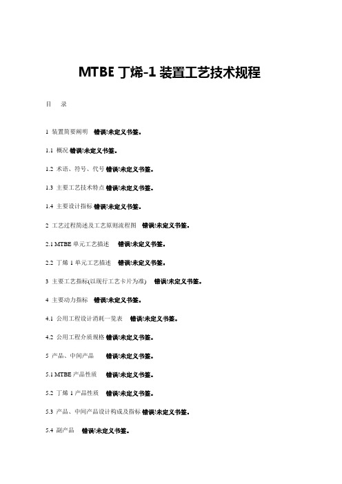
High PrecisionOPERATIONAL AMPLIFIERSOPA277OPA2277OPA4277SBOS079A – MARCH 1999 – REVISED APRIL 2005PRODUCTION DATA information is current as of publication date.Products conform to specifications per the terms of Texas Instruments standard warranty. Production processing does not necessarily include testing of all parameters.Copyright © 1999-2005, Texas Instruments IncorporatedPlease be aware that an important notice concerning availability, standard warranty, and use in critical applications of Texas Instruments semiconductor products and disclaimers thereto appears at the end of this data sheet.All trademarks are the property of their respective owners.DESCRIPTIONThe OPA277 series precision op amps replace the industry standard OP-177. They offer improved noise, wider output voltage swing, and are twice as fast with half the quiescent current. Features include ultra low offset voltage and drift, low bias current, high common-mode rejection, and high power supply rejection. Single, dual, and quad versions have identical specifications for maximum design flexibility.OPA277 series op amps operate from ±2V to ±18V supplies with excellent performance. Unlike most op amps which are specified at only one supply voltage, the OPA277 series is specified for real-world applications; a single limit applies over the ±5V to ±15V supply range. High performance is maintained as the amplifiers swing to their specified limits. Because the initial offset voltage (±20µV max) is so low, user adjustment is usually not required. However, the single version (OPA277) provides exter-nal trim pins for special applications.OPA277 op amps are easy to use and free from phase inversion and overload problems found in some other op amps. They are stable in unity gain and provide excellent dynamic behavior over a wide range of load conditions. Dual and quad versions feature completely independent circuitry for lowest crosstalk and free-dom from interaction, even when overdriven or overloaded.Single (OPA277) and dual (OPA2277) versions are available in DIP-8, SO-8, and DFN-8 (4mm x 4mm) packages. The quad (OPA4277) comes in DIP-14 and SO-14 surface-mount pack-ages. All are fully specified from –40°C to +85°C and operate from –55°C to +125°C.FEATURESq ULTRA LOW OFFSET VOLTAGE: 10µV q ULTRA LOW DRIFT: ±0.1µV/°C q HIGH OPEN-LOOP GAIN: 134dBq HIGH COMMON-MODE REJECTION: 140dB q HIGH POWER SUPPLY REJECTION: 130dB q LOW BIAS CURRENT: 1nA maxq WIDE SUPPLY RANGE: ±2V to ±18Vq LOW QUIESCENT CURRENT: 800µA/amplifier q SINGLE, DUAL, AND QUAD VERSIONS q REPLACES OP-07, OP-77, OP-1771234567141312111098Out D –In D +In D V –+In C –In C Out COut A –In A +In A V++In B–In B Out BOPA427714-Pin DIP, SO-14ADBC12348765V+Out B –In B +In BOut A –In A +In A V –OPA22778-Pin DIP, SO-8ABAPPLICATIONSq TRANSDUCER AMPLIFIER q BRIDGE AMPLIFIERq TEMPERATURE MEASUREMENTS q STRAIN GAGE AMPLIFIER q PRECISION INTEGRATORq BATTERY POWERED INSTRUMENTS q TEST EQUIPMENT12348765Offset Trim V+Output NCOffset Trim–In +In V –OPA2778-Pin DIP, SO-8Offset Trim −In +In V −OPA277AIDRM(Connect to V −)Out A −In A+In AV −OPA2277AIDRM(Connect to V −)NC = No connection.OFFSET OFFSETVOLTAGE VOLTAGE DRIFT PRODUCT max, µV max, µV/°CPACKAGE-LEAD SingleOPA277PA ±50±1DIP-8OPA277P ±20±0.15DIP-8OPA277UA ±50±1SO-8 Surface Mount OPA277U±20±0.15SO-8 Surface Mount OPA277AIDRM ±100±1DFN-8 (4mm x 4mm)DualOPA2277PA ±50±1DIP-8OPA2277P ±25±0.25DIP-8OPA2277UA ±50±1SO-8 Surface Mount OPA2277U±25±0.25SO-8 Surface Mount OPA2277AIDRM ±100±1DFN-8 (4mm x 4mm)QuadOPA4277PA ±50±1DIP-14OPA4277UA±50±1SO-14 Surface MountNOTE: (1) For the most current package and ordering information, see the Package Option Addendum located at the end of this data sheet or visit the TI web site at .ABSOLUTE MAXIMUM RATINGS (1)Supply Voltage ....................................................................................36V Input Voltage .....................................................(V –) –0.7V to (V+) +0.7V Output Short-Circuit (2)..............................................................Continuous Operating Temperature ..................................................–55°C to +125°C Storage Temperature .....................................................–55°C to +125°C Junction Temperature......................................................................150°C Lead Temperature (soldering, 10s).................................................300°C ESD Rating (Human Body Model).. (2000V)(Machine Model)...........................................................100V NOTE: (1) Stresses above these rating may cause permanent damage.Exposure to absolute maximum conditions for extended periods may degrade device reliability. (2) Short-circuit to ground, one amplifier per package.PACKAGE/ORDERING INFORMATION (1)PIN DESCRIPTIONSELECTROSTATICDISCHARGE SENSITIVITYThis integrated circuit can be damaged by ESD. Texas Instru-ments recommends that all integrated circuits be handled with appropriate precautions. Failure to observe proper handling and installation procedures can cause damage.ESD damage can range from subtle performance degradation to complete device failure. Precision integrated circuits may be more susceptible to damage because very small parametric changes could cause the device not to meet its published specifications.ELECTRICAL CHARACTERISTICS: V S = ±5V to V S = ±15VAt T A = +25°C, and R L = 2kΩ, unless otherwise noted.Boldface limits apply over the specified temperature range, –40°C to +85°C.OPA277PA, UAOPA277P, U OPA2277PA, UA OPA277AIDRM,OPA2277P, U OPA4277PA, UA OPA2277AIDRMPARAMETER CONDITION MIN TYP(1)MAX MIN TYP(1)MAX MIN TYP(1)MAX UNITSOFFSET VOLTAGEInput Offset Voltage:V OSOPA277P, U (high grade, single)±10±20µV OPA2277P, U (high grade, dual)±10±25µV All PA, UA, Versions±20±50µV AIDRM Versions±35±100µV Input Offset Voltage Over TemperatureOPA277P, U (high grade, single)T A = –40°C to +85°C±30µV OPA2277P, U (high grade, dual)T A = –40°C to +85°C±50µV All PA, UA, Versions T A = –40°C to +85°C±100µV AIDRM Versions T A = –40°C to +85°C±165µV Input Offset Voltage Drift dV OS/dTOPA277P, U (high grade, single)T A = –40°C to +85°C±0.1±0.15µV/°C OPA2277P, U (high grade, dual)T A = –40°C to +85°C±0.1±0.25µV/°C All PA, UA, AIDRM Versions T A = –40°C to +85°C±0.15±1±0.15±1µV/°C Input Offset Voltage: (all models)vs Time0.2✻✻µV/mo vs Power Supply PSRR V S = ±2V to ±18V±0.3±0.5✻±1✻±1µV/V T A = –40°C to +85°C V S = ±2V to ±18V±0.5±1±1µV/V Channel Separation (dual, quad)dc0.1✻✻µV/V INPUT BIAS CURRENTInput Bias Current I B±0.5±1✻±2.8±2.8nA T A = –40°C to +85°C±2±4±4nA Input Offset Current I OS±0.5±1✻±2.8±2.8nA T A = –40°C to +85°C±2±4±4nA NOISEInput Voltage Noise, f = 0.1 to 10Hz0.22✻✻µV PP0.035✻✻µVrms Input Voltage Noise Density, f = 10Hz e n12✻✻nV/√Hzf = 100Hz8✻✻nV/√Hzf = 1kHz8✻✻nV/√Hzf = 10kHz8✻✻nV/√Hz Current Noise Density, f = 1kHz i n0.2✻✻pA/√HzINPUT VOLTAGE RANGECommon-Mode Voltage Range V CM(V–) +2(V+) –2✻✻✻✻V Common-Mode Rejection CMRR V CM = (V–) +2V to (V+) –2V130140115✻115✻dB T A = –40°C to +85°C V CM = (V–) +2V to (V+) –2V128115115dB INPUT IMPEDANCEDifferential100 || 3✻✻MΩ || pF Common-Mode V CM = (V–) +2V to (V+) –2V250 || 3✻✻GΩ || pFOPEN-LOOP GAINOpen-Loop Voltage Gain A OL V O = (V–)+0.5V to(V+)–1.2V, R L = 10kΩ140✻✻dBV O = (V–)+1.5V to(V+)–1.5V, R L = 2kΩ126134✻✻✻✻dBT A = –40°C to +85°C V O = (V–)+1.5V to(V+)–1.5V, R L = 2kΩ126✻✻dBFREQUENCY RESPONSEGain-Bandwidth Product GBW1✻✻MHz Slew Rate SR0.8✻✻V/µs Settling Time, 0.1%V S = ±15V, G = 1, 10V Step14✻✻µs0.01%V S = ±15V, G = 1, 10V Step16✻✻µs Overload Recovery Time V IN• G = V S3✻✻µs Total Harmonic Distortion + Noise THD+N1kHz, G = 1, V O = 3.5Vrms0.002✻✻%✻ Specifications same as OPA277P, U.NOTE: (1) V S = ±15V.OPA277, OPA2277, OPA42773 SBOS079A ELECTRICAL CHARACTERISTICS: V S = ±5V to V S = ±15V (CONT) At T A = +25°C, and R L = 2kΩ, unless otherwise noted.Boldface limits apply over the specified temperature range, –40°C to +85°C.✻ Specifications same as OPA277P, U.NOTES:(1) V S = ±15V.(2) Thermal pad soldered to printed circuit board (PCB).OPA277, OPA2277, OPA42775SBOS079ATYPICAL CHARACTERISTICSAt T A = +25°C, V S = ±15V, and R L = 2k Ω, unless otherwise noted.101001k10k100kFrequency (Hz)CHANNEL SEPARATION vs FREQUENCY1M140120100806040C h a n n e l S e p a r a t i o n (d B)101001k 10k100k10.10.010.001T H D +N o i s e (%)Frequency (Hz)TOTAL HARMONIC DISTORTION + NOISEvs FREQUENCY1101001k10k1000100101V o l t a g e N o i s e (n V/√H z )C u r r e n t N o i s e (f A /√H z )Frequency (Hz)INPUT NOISE AND CURRENT NOISE SPECTRAL DENSITY vs FREQUENCY0.11101001k10k100k1M10M 140120100806040200–20A O L (dB )0–30–60–90–120–150–180P h a s e (°)Frequency (Hz)OPEN-LOOP GAIN/PHASEvs FREQUENCY0.11101001k 10k 100k 1M140120100806040200P S R , C M R (d B )Frequency (Hz)POWER SUPPLY AND COMMON-MODEREJECTION vs FREQUENCY1s/divINPUT NOISE VOLTAGE vs TIME50n V /d i vNoise signal is bandwidth limited to lie between 0.1Hz and 10Hz.TYPICAL CHARACTERISTICS (CONT)At T A = +25°C, V S = ±15V, and R L = 2k Ω, unless otherwise noted.OFFSET VOLTAGE PRODUCTION DISTRIBUTIONP e r c e n t o f A m p l i f i e r s (%)Offset Voltage (µV)16141210864203210–1–2–3O f f s e t V o l t a g e C h a n g e (µV )306090120Time from Power Supply Turn-On (s)WARM-UP OFFSET VOLTAGE DRIFT154575105OFFSET VOLTAGE DRIFT PRODUCTION DISTRIBUTIONP e r c e n t o f Am p l i f i e r s (%)Offset Voltage (µV/°C)00.10.20.30.40.50.60.70.80.9 1.035302520151050INPUT BIAS CURRENT vs TEMPERATURE125Temperature (°C)–75–50–25255075100543210–1–2–3–4–5I n p u t B i a s C u r r e n t (n A )–75–50–250255075100125160150140130120110100A O L , C M R , P S R (dB )Temperature (°C)A OL , CMR, PSR vs TEMPERATURE–75–50–252550751001251000950900850800750700650600550500Q u i e s c e n t C u r r e n t (µA )1009080706050403020100S h o r t -C i r c u i t C u r r e n t (m A )Temperature (°C)QUIESCENT CURRENT ANDSHORT-CIRCUIT CURRENT vs TEMPERATUREOPA277, OPA2277, OPA42777SBOS079ATYPICAL CHARACTERISTICS (CONT)At T A = +25°C, V S = ±15V, and R L = 2k Ω, unless otherwise noted.CHANGE IN INPUT BIAS CURRENT vs POWER SUPPLY VOLTAGE40Supply Voltage (V)51015202530352.01.51.00.50.0–0.5–1.0–1.5–2.0∆I B (n A )CHANGE IN INPUT BIAS CURRENT vs COMMON-MODE VOLTAGE15Common-Mode Voltage (V)–15–10–505102.01.51.00.50.0–0.5–1.0–1.5–2.0∆I B (n A)OUTPUT VOLTAGE SWING vs OUTPUT CURRENT(V+) –(V+) –(V+) –(V+) –(V+) –(V –(V –(V –(V –(V –(V –0±5±10±15±20±25±30Output Current (mA)O u t p u t V o l t a g e S w i n g (V )1000900800700600500Q u i e s c e n t C ur r e n t (µA )±5±10±15±20Supply Voltage (V)QUIESCENT CURRENT vs SUPPLY VOLTAGEper amplifier100102050S e t t l i n g T i m e (µs )±1±10±100Gain (V/V)SETTLING TIME vs CLOSED-LOOP GAIN MAXIMUM OUTPUT VOLTAGEvs FREQUENCY1MFrequency (Hz)1k10k100k302520151050O u t p u t V o l t a g e (V P P )TYPICAL CHARACTERISTICS (CONT)At T A = +25°C, V S = ±15V, and R L = 2k Ω, unless otherwise noted.SMALL-SIGNAL OVERSHOOT vs LOAD CAPACITANCE1k1001010k100kLoad Capacitance (pF)6050403020100O v e r s h o o t (%)10µs/divLARGE-SIGNAL STEP RESPONSE G = +1, CL = 1500pF, V S = +15V2V /d i v1µs/divSMALL-SIGNAL STEP RESPONSEG = +1, CL = 0, V S = ±15V20m V /d i v1µs/divSMALL-SIGNAL STEP RESPONSE G = +1, C L = 1500pF, V S = ±15V20m V /d i vAPPLICATIONS INFORMATION The OPA277 series is unity-gain stable and free from unex-pected output phase reversal, making it easy to use in a wide range of applications. Applications with noisy or high imped-ance power supplies may require decoupling capacitors connecting a potentiometer as shown in Figure 1. This adjustment should be used only to null the offset of the op amp. This adjustment should not be used to compensate for offsets created elsewhere in a system since this can intro-duce additional temperature drift.FIGURE 2. Input Bias Current Cancellation.OPA277, OPA2277, OPA42779 SBOS079A FIGURE 3. Load Cell Amplifier.FIGURE 4. Thermocouple Low Offset, Low Drift Loop Measurement with Diode Cold Junction Compensation.DFN PACKAGEThe OPA277 series uses the 8-lead DFN (also known as SON), which is a QFN package with contacts on only two sides of the package bottom. This leadless, near-chip-scale package maximizes board space and enhances thermal and electrical characteristics through an exposed pad.DFN packages are physically small, have a smaller routing area, improved thermal performance, and improved electrical parasitics, with a pinout scheme that is consistent with other commonly-used packages, such as SO and MSOP. Addition-ally, the absence of external leads eliminates bent-lead issues.The DFN package can be easily mounted using standard printed circuit board (PCB) assembly techniques. See Appli-cation Note, QFN/SON PCB Attachment (SLUA271) and Application Report, Quad Flatpack No-Lead Logic Packages (SCBA017), both available for download at . The exposed leadframe die pad on the bottom of the package should be connected to V–.LAYOUT GUIDELINESThe leadframe die pad should be soldered to a thermal pad on the PCB. Mechanical drawings located at the end of this data sheet list the physical dimensions for the package and pad.Soldering the exposed pad significantly improves board-level reliability during temperature cycling, key push, package shear, and similar board-level tests. Even with applications that have low-power dissipation, the exposed pad must be soldered to the PCB to provide structural integrity and long-term reliability.Addendum-Page 1PACKAGING INFORMATIONOrderable Device Status(1)Package Type PackageDrawingPins Package QtyEco Plan(2)Lead/Ball FinishMSL Peak Temp(3)Samples (Requires Login)OPA2277AIDRMT ACTIVE VSON DRM 8250Green (RoHS & no Sb/Br)CU NIPDAU Level-1-260C-UNLIM OPA2277AIDRMTG4ACTIVE VSON DRM 8250Green (RoHS & no Sb/Br)CU NIPDAU Level-1-260C-UNLIM OPA2277P ACTIVE PDIP P 850Green (RoHS & no Sb/Br)CU NIPDAU N / A for Pkg Type OPA2277PA ACTIVE PDIP P 850Green (RoHS & no Sb/Br)CU NIPDAU N / A for Pkg Type OPA2277PAG4ACTIVE PDIP P 850Green (RoHS & no Sb/Br)CU NIPDAU N / A for Pkg Type OPA2277PG4ACTIVE PDIP P 850Green (RoHS & no Sb/Br)CU NIPDAU N / A for Pkg Type OPA2277U ACTIVE SOIC D 875Green (RoHS & no Sb/Br)Call TI Level-3-260C-168 HR OPA2277U/2K5ACTIVE SOIC D 82500Green (RoHS & no Sb/Br)Call TI Level-3-260C-168 HR OPA2277U/2K5G4ACTIVE SOIC D 82500Green (RoHS & no Sb/Br)Call TI Level-3-260C-168 HR OPA2277UA ACTIVE SOIC D 875Green (RoHS & no Sb/Br)Call TILevel-3-260C-168 HROPA2277UA/2K5ACTIVE SOIC D 82500Green (RoHS & no Sb/Br)CU NIPDAU Level-3-260C-168 HR OPA2277UA/2K5E4ACTIVE SOIC D 82500Green (RoHS & no Sb/Br)CU NIPDAU Level-3-260C-168 HR OPA2277UAE4ACTIVE SOIC D 875Green (RoHS & no Sb/Br)Call TI Level-3-260C-168 HR OPA2277UAG4ACTIVE SOIC D 875Green (RoHS & no Sb/Br)Call TI Level-3-260C-168 HR OPA2277UG4ACTIVE SOIC D 875Green (RoHS & no Sb/Br)Call TILevel-3-260C-168 HROPA277AIDRMR ACTIVE VSON DRM 83000Green (RoHS & no Sb/Br)CU NIPDAU Level-1-260C-UNLIM OPA277AIDRMRG4ACTIVEVSONDRM83000Green (RoHS & no Sb/Br)CU NIPDAU Level-1-260C-UNLIM芯天下--/Addendum-Page 2Orderable Device Status(1)Package Type PackageDrawingPins Package QtyEco Plan(2)Lead/Ball FinishMSL Peak Temp(3)Samples (Requires Login)OPA277AIDRMT ACTIVE VSON DRM 8250Green (RoHS & no Sb/Br)CU NIPDAU Level-1-260C-UNLIM OPA277AIDRMTG4ACTIVE VSON DRM 8250Green (RoHS & no Sb/Br)CU NIPDAU Level-1-260C-UNLIM OPA277P ACTIVE PDIP P 850Green (RoHS & no Sb/Br)CU NIPDAU N / A for Pkg Type OPA277PA ACTIVE PDIP P 850Green (RoHS & no Sb/Br)CU NIPDAU N / A for Pkg Type OPA277PAG4ACTIVE PDIP P 850Green (RoHS & no Sb/Br)CU NIPDAU N / A for Pkg Type OPA277PG4ACTIVE PDIP P 850Green (RoHS & no Sb/Br)CU NIPDAU N / A for Pkg Type OPA277U ACTIVE SOIC D 875Green (RoHS & no Sb/Br)CU NIPDAU Level-3-260C-168 HR OPA277U/2K5ACTIVE SOIC D 82500Green (RoHS & no Sb/Br)CU NIPDAU Level-3-260C-168 HR OPA277U/2K5G4ACTIVE SOIC D 82500Green (RoHS & no Sb/Br)CU NIPDAU Level-3-260C-168 HR OPA277UA ACTIVE SOIC D 875Green (RoHS & no Sb/Br)CU NIPDAU Level-3-260C-168 HR OPA277UA/2K5ACTIVE SOIC D 82500Green (RoHS & no Sb/Br)CU NIPDAU Level-3-260C-168 HR OPA277UA/2K5E4ACTIVE SOIC D 82500Green (RoHS & no Sb/Br)CU NIPDAU Level-3-260C-168 HR OPA277UAE4ACTIVE SOIC D 875Green (RoHS & no Sb/Br)CU NIPDAU Level-3-260C-168 HR OPA277UAG4ACTIVE SOIC D 875Green (RoHS & no Sb/Br)CU NIPDAU Level-3-260C-168 HR OPA277UG4ACTIVE SOIC D 875Green (RoHS & no Sb/Br)CU NIPDAU Level-3-260C-168 HR OPA4277PA ACTIVE PDIP N 1425Green (RoHS & no Sb/Br)CU NIPDAU N / A for Pkg Type OPA4277PAG4ACTIVE PDIP N 1425Green (RoHS & no Sb/Br)CU NIPDAU N / A for Pkg Type OPA4277UAACTIVESOICD1450Green (RoHS & no Sb/Br)CU NIPDAU Level-3-260C-168 HR芯天下--/Addendum-Page 3Orderable Device Status(1)Package Type PackageDrawingPins Package QtyEco Plan(2)Lead/Ball FinishMSL Peak Temp(3)Samples (Requires Login)OPA4277UA/2K5ACTIVE SOIC D 142500Green (RoHS & no Sb/Br)CU NIPDAU Level-3-260C-168 HR OPA4277UA/2K5E4ACTIVE SOIC D 142500Green (RoHS & no Sb/Br)CU NIPDAU Level-3-260C-168 HR OPA4277UAE4ACTIVE SOIC D 1450Green (RoHS & no Sb/Br)CU NIPDAU Level-3-260C-168 HR OPA4277UAG4ACTIVESOICD1450Green (RoHS & no Sb/Br)CU NIPDAU Level-3-260C-168 HR(1)The marketing status values are defined as follows:ACTIVE: Product device recommended for new designs.LIFEBUY: TI has announced that the device will be discontinued, and a lifetime-buy period is in effect.NRND: Not recommended for new designs. Device is in production to support existing customers, but TI does not recommend using this part in a new design.PREVIEW: Device has been announced but is not in production. Samples may or may not be available.OBSOLETE: TI has discontinued the production of the device.(2)Eco Plan - The planned eco-friendly classification: Pb-Free (RoHS), Pb-Free (RoHS Exempt), or Green (RoHS & no Sb/Br) - please check /productcontent for the latest availability information and additional product content details.TBD: The Pb-Free/Green conversion plan has not been defined.Pb-Free (RoHS): TI's terms "Lead-Free" or "Pb-Free" mean semiconductor products that are compatible with the current RoHS requirements for all 6 substances, including the requirement that lead not exceed 0.1% by weight in homogeneous materials. Where designed to be soldered at high temperatures, TI Pb-Free products are suitable for use in specified lead-free processes.Pb-Free (RoHS Exempt): This component has a RoHS exemption for either 1) lead-based flip-chip solder bumps used between the die and package, or 2) lead-based die adhesive used between the die and leadframe. The component is otherwise considered Pb-Free (RoHS compatible) as defined above.Green (RoHS & no Sb/Br): TI defines "Green" to mean Pb-Free (RoHS compatible), and free of Bromine (Br) and Antimony (Sb) based flame retardants (Br or Sb do not exceed 0.1% by weight in homogeneous material)(3)MSL, Peak Temp. -- The Moisture Sensitivity Level rating according to the JEDEC industry standard classifications, and peak solder temperature.Important Information and Disclaimer:The information provided on this page represents TI's knowledge and belief as of the date that it is provided. TI bases its knowledge and belief on information provided by third parties, and makes no representation or warranty as to the accuracy of such information. Efforts are underway to better integrate information from third parties. TI has taken and continues to take reasonable steps to provide representative and accurate information but may not have conducted destructive testing or chemical analysis on incoming materials and chemicals.TI and TI suppliers consider certain information to be proprietary, and thus CAS numbers and other limited information may not be available for release.In no event shall TI's liability arising out of such information exceed the total purchase price of the TI part(s) at issue in this document sold by TI to Customer on an annual basis.芯天下--/TAPE AND REEL INFORMATION*All dimensions are nominalDevicePackage Type Package Drawing Pins SPQReel Diameter (mm)Reel Width W1(mm)A0(mm)B0(mm)K0(mm)P1(mm)W (mm)Pin1Quadrant OPA2277AIDRMT VSON DRM 8250180.012.4 4.25 4.25 1.158.012.0Q2OPA2277U/2K5SOIC D 82500330.012.4 6.4 5.2 2.18.012.0Q1OPA2277UA/2K5SOIC D 82500330.012.4 6.4 5.2 2.18.012.0Q1OPA277AIDRMR VSON DRM 83000330.012.4 4.25 4.25 1.158.012.0Q2OPA277AIDRMT VSON DRM 8250180.012.4 4.25 4.25 1.158.012.0Q2OPA277U/2K5SOIC D 82500330.012.4 6.4 5.2 2.18.012.0Q1OPA277UA/2K5SOIC D 82500330.012.4 6.4 5.2 2.18.012.0Q1OPA4277UA/2K5SOICD142500330.016.46.59.02.18.016.0Q1*All dimensions are nominalDevice Package Type Package Drawing Pins SPQ Length(mm)Width(mm)Height(mm) OPA2277AIDRMT VSON DRM8250210.0185.035.0 OPA2277U/2K5SOIC D8*******.0367.035.0 OPA2277UA/2K5SOIC D8*******.0367.035.0 OPA277AIDRMR VSON DRM83000367.0367.035.0 OPA277AIDRMT VSON DRM8250210.0185.035.0 OPA277U/2K5SOIC D8*******.0367.035.0 OPA277UA/2K5SOIC D8*******.0367.035.0OPA4277UA/2K5SOIC D142500367.0367.038.0IMPORTANT NOTICETexas Instruments Incorporated and its subsidiaries(TI)reserve the right to make corrections,enhancements,improvements and other changes to its semiconductor products and services per JESD46C and to discontinue any product or service per JESD48B.Buyers should obtain the latest relevant information before placing orders and should verify that such information is current and complete.All semiconductor products(also referred to herein as“components”)are sold subject to TI’s terms and conditions of sale supplied at the time of order acknowledgment.TI warrants performance of its components to the specifications applicable at the time of sale,in accordance with the warranty in TI’s terms and conditions of sale of semiconductor products.Testing and other quality control techniques are used to the extent TI deems necessary to support this warranty.Except where mandated by applicable law,testing of all parameters of each component is not necessarily performed.TI assumes no liability for applications assistance or the design of Buyers’products.Buyers are responsible for their products and applications using TI components.To minimize the risks associated with Buyers’products and applications,Buyers should provide adequate design and operating safeguards.TI does not warrant or represent that any license,either express or implied,is granted under any patent right,copyright,mask work right,or other intellectual property right relating to any combination,machine,or process in which TI components or services are rmation published by TI regarding third-party products or services does not constitute a license to use such products or services or a warranty or endorsement e of such information may require a license from a third party under the patents or other intellectual property of the third party,or a license from TI under the patents or other intellectual property of TI.Reproduction of significant portions of TI information in TI data books or data sheets is permissible only if reproduction is without alteration and is accompanied by all associated warranties,conditions,limitations,and notices.TI is not responsible or liable for such altered rmation of third parties may be subject to additional restrictions.Resale of TI components or services with statements different from or beyond the parameters stated by TI for that component or service voids all express and any implied warranties for the associated TI component or service and is an unfair and deceptive business practice. TI is not responsible or liable for any such statements.Buyer acknowledges and agrees that it is solely responsible for compliance with all legal,regulatory and safety-related requirements concerning its products,and any use of TI components in its applications,notwithstanding any applications-related information or support that may be provided by TI.Buyer represents and agrees that it has all the necessary expertise to create and implement safeguards which anticipate dangerous consequences of failures,monitor failures and their consequences,lessen the likelihood of failures that might cause harm and take appropriate remedial actions.Buyer will fully indemnify TI and its representatives against any damages arising out of the use of any TI components in safety-critical applications.In some cases,TI components may be promoted specifically to facilitate safety-related applications.With such components,TI’s goal is to help enable customers to design and create their own end-product solutions that meet applicable functional safety standards and requirements.Nonetheless,such components are subject to these terms.No TI components are authorized for use in FDA Class III(or similar life-critical medical equipment)unless authorized officers of the parties have executed a special agreement specifically governing such use.Only those TI components which TI has specifically designated as military grade or“enhanced plastic”are designed and intended for use in military/aerospace applications or environments.Buyer acknowledges and agrees that any military or aerospace use of TI components which have not been so designated is solely at the Buyer's risk,and that Buyer is solely responsible for compliance with all legal and regulatory requirements in connection with such use.TI has specifically designated certain components which meet ISO/TS16949requirements,mainly for automotive ponents which have not been so designated are neither designed nor intended for automotive use;and TI will not be responsible for any failure of such components to meet such requirements.Products ApplicationsAudio /audio Automotive and Transportation /automotiveAmplifiers Communications and Telecom /communicationsData Converters Computers and Peripherals /computersDLP®Products Consumer Electronics /consumer-appsDSP Energy and Lighting /energyClocks and Timers /clocks Industrial /industrialInterface Medical /medicalLogic Security /securityPower Mgmt Space,Avionics and Defense /space-avionics-defense Microcontrollers Video and Imaging /videoRFID OMAP Mobile Processors /omap TI E2E Community Wireless Connectivity /wirelessconnectivityMailing Address:Texas Instruments,Post Office Box655303,Dallas,Texas75265Copyright©2012,Texas Instruments Incorporated。
电子测量技术基础-示波器

输 入
R1
C1
R2
C2 输 出
通常用一个波段开关换接不同的R2C2来改变衰减量。在面板上, 直接标注与各档衰减量对应的偏转灵敏度,单位为V/DIV。
30
阻抗变换器
常采用射极跟随器, ①输入阻抗大,使示波器对外呈现高输入阻抗.
②输出阻抗小,使后接低阻延迟线相匹配.
前置放大器
前置放大器将信号适当放大,从中取出内触发信号,并具有 灵敏度微调、校正、Y轴移位、极性反转等控制作用。
43
例:用示波器观测正弦波时,荧光屏上得到如图 所示波形,试分析示波器哪个部分工作不正常?
(1)为扫描锯齿波线性度不好; (2)Y放大器引入失真,出现削顶,产生截止失真; (3)有扫描回线,增辉电路工作不正常。
44
日立V252模拟示波器面板
45
三、双踪示波器
其垂直偏转通道由A和B两个通道组成。两个通道 的信号在电子开关的控制下,交替加在示波管的垂直 偏转板上,从而显示两个波形。
在两个脉冲间隔时间内没有扫描.故不会产生很亮的时间基线.一般 示波器采用此方法.
Ts
(a)被测脉冲 t
(d)触发扫描 t 能较好地观测脉冲 扫描 等待
22
比较各自情况
无法观察细节
波形底部(时间基线) 很亮,而波形自身不亮
底部没有基线
23
扫描过程的增辉和隐熄
上面的分析都假定扫描回程时间为零,实际上回扫是需要 一定时间的,为了在荧光屏上不显示回扫过程,可采用增辉 行程或隐熄回程的办法,将电子束在回程期间关闭。 增辉是对应扫描行程,隐熄则是对应扫描回程。
C 将示波器输入耦合开关置于“GND”地输入位置,调节垂直
位移旋钮,使屏幕上的扫描线(零电平线)移到荧光屏的中间 位置,即确定零电平线。以后不再调制垂直位置旋钮。
施耐德7.2kV-40.5kV FP系列户内高压六氟化硫断路器

7.2-40.5kV FP 系列 户内高压六氟化硫断路器
目录
介绍 ............................................................................................... 2 前言 ........................................................................................................... 2 标准..................................................................... 2 用户受益 .................................................................................................... 2
外形及安装尺寸图 .........................................................................11 手车式 .......................................................................................................11
7.2-40.5kV FP 系列
户内高压六氟化硫断路器
产品目录
施耐德电气
善用其效 尽享其能
全球能效管理专家施耐德电气为世界100多个国家提供整体解决方案,其中在能源与基 础设施、工业过程控制、楼宇自动化和数据中心与网络等市场处于世界领先地位,在 住宅应用领域也拥有强大的市场能力。致力于为客户提供安全、可靠、高效的能源, 施耐德电气2010年的销售额为196亿欧元,拥有超过110,000名员工。施耐德电气助 您——善用其效,尽享其能!
Perkadox PF-MT40商品说明书

Product Data SheetPerkadox PF-MT40tert-Butyl monoperoxymaleate, 40% in dibutyl maleatePerkadox® PF-MT40 is a 40% suspension which is used for room temperature curing of acrylic solid surface without yellow discoloration. It is used in combination with Accelerator CTAS for room temperature cure.CAS number1931-62-0EINECS/ELINCS No.217-691-1TSCA statuslisted on inventoryMolecular weight188.2Active oxygen contentperoxide8.5%Concentration3.23-3.57%SpecificationsAppearance PasteAssay38.0 - 42.0 %CharacteristicsDensity, 25 °C0.850 g/cm³Viscosity, 25 °C25000-50000 mPa.sApplicationsPerkadox® PF-MT40 can be used as for the ambient temperature curing of MMA resins. Without the addition of an accelerator, the cure of the acrylate resin starts only above the activation temperature of 90°C. For the cure at ambient temperature, Perkadox® PF-MT40 must be accelerated with a combination of special accelerators. Together with the Accelerators R-913 and Ca(OH)2, a reasonable geltime is obtained with a fast cure at ambient temperatures. The most important advantage of a cure system based on Perkadox® PF-MT 40 is the absence of yellow discoloration and a lower residual monomer content compared to results obtained with a BPO/amine curing system.Thermal stabilityOrganic peroxides are thermally unstable substances, which may undergo self-accelerating decomposition. The lowest temperature at which self-accelerating decomposition of a substance in the original packaging may occur is the Self-Accelerating Decomposition Temperature (SADT). The SADT is determined on the basis of the Heat Accumulation Storage Test.SADT50°C (122°F)Method The Heat Accumulation Storage Test is a recognized test method for thedetermination of the SADT of organic peroxides (see Recommendations on theTransport of Dangerous Goods, Manual of Tests and Criteria - United Nations, NewYork and Geneva).StorageDue to the relatively unstable nature of organic peroxides a loss of quality can be detected over a period of time. To minimize the loss of quality, Nouryon recommends a maximum storage temperature (Ts max. ) for each organic peroxide product.Ts Max.25°C (77°F)Note When stored under the recommended storage conditions, Perkadox® PF-MT40will remain within the Nouryon specifications for a period of at least 3 months afterdelivery.Packaging and transportIn North America Perkadox® PF-MT40 is packed in non-returnable, 5 gallon polyethylene containers of 39.7 lb net weight. In other regions the standard packaging is plastic pails for 14 kg peroxide. Both packaging and transport meet the international regulations. For the availability of other packed quantities contact your Nouryon representative.Perkadox®PF-MT40 is classified as Organic peroxide type E; solid, Division 5.2; UN 3108; PG I.Safety and handlingKeep containers tightly closed. Store and handle Perkadox® PF-MT40 in a dry well-ventilated place away from sources of heat or ignition and direct sunlight. Never weigh out in the storage room.Avoid contact with reducing agents (e.g. amines), acids, alkalis and heavy metal compounds (e.g. accelerators, driers and metal soaps). Please refer to the Safety Data Sheet (SDS) for further information on the safe storage, use and handling of Perkadox® PF-MT40. This information should be thoroughly reviewed prior to acceptance of this product.The SDS is available at /sds-search.All information concerning this product and/or suggestions for handling and use contained herein are offered in good faith and are believed to be reliable.Nouryon, however, makes no warranty as to accuracy and/or sufficiency of such information and/or suggestions, as to the product's merchantability or fitness for any particular purpose, or that any suggested use will not infringe any patent. Nouryon does not accept any liability whatsoever arising out of the use of or reliance on this information, or out of the use or the performance of the product. Nothing contained herein shall be construed as granting or extending any license under any patent. Customer must determine for himself, by preliminary tests or otherwise, the suitability of this product for his purposes.The information contained herein supersedes all previously issued information on the subject matter covered. The customer may forward, distribute, and/or photocopy this document only if unaltered and complete, including all of its headers and footers, and should refrain from any unauthorized use. Don’t copythis document to a website.Perkadox® is a registered trademark of Nouryon Functional Chemicals B.V. or affiliates in one or more territories.Contact UsPolymer Specialties Americas************************Polymer Specialties Europe, Middle East, India and Africa*************************Polymer Specialties Asia Pacific************************2022-6-30© 2022Thermoset composites Perkadox PF-MT40。
OPA277PA中文资料

IInternational Airport Industrial Park • Mailing Address: PO Box 11400, Tucson, AZ 85734 • Street Address: 6730 S. Tucson Blvd., Tucson, AZ 85706 • Tel: (520) 746-1111 Twx: 910-952-1111 • Internet: / • Cable: BBRCORP • Telex: 066-6491 • FAX: (520) 889-1510 • Immediate Product Info: (800) 548-6132
TA = –40°C to +85°C
VCM CMRR
INPUT IMPEDANCE Differential Common-Mode
OPEN-LOOP GAIN
Open-Loop Voltage Gain
AOL
TA = –40°C to +85°C
FREQUENCY RESPONSE
Gain-Bandwidth Product
OPA277 op amps are easy to use and free from phase inversion and overload problems found in some other op amps. They are stable in unity gain and provide excellent dynamic behavior over a wide range of load conditions. Dual and quad versions feature completely independent circuitry for lowest crosstalk and freedom from interaction, even when overdriven or overloaded.
MTBE丁烯-1装置工艺技术规程
MTBE丁烯-1装置工艺技术规程目录1 装置简要阐明错误!未定义书签。
1.1 概况错误!未定义书签。
1.2 术语、符号、代号错误!未定义书签。
1.3 主要工艺技术特点错误!未定义书签。
1.4 主要设计指标错误!未定义书签。
2 工艺过程简述及工艺原则流程图错误!未定义书签。
2.1 MTBE单元工艺描述错误!未定义书签。
2.2 丁烯-1单元工艺描述错误!未定义书签。
3 主要工艺指标(以现行工艺卡片为准) 错误!未定义书签。
4 主要动力指标错误!未定义书签。
4.1 公用工程设计消耗一览表错误!未定义书签。
4.2 公用工程介质规格错误!未定义书签。
5 产品、中间产品错误!未定义书签。
5.1 MTBE产品性质错误!未定义书签。
5.2 丁烯-1产品性质错误!未定义书签。
5.3 产品、中间产品设计构成及指标错误!未定义书签。
5.4 副产品错误!未定义书签。
6 主要原料及化工原材料质量指标错误!未定义书签。
6.1 主要原料错误!未定义书签。
6.2 化工原材料错误!未定义书签。
7 装置开、停工方案错误!未定义书签。
7.1 装置动工方案错误!未定义书签。
7.2 装置停工方案错误!未定义书签。
8 事故处理错误!未定义书签。
8.1 事故处理旳原则错误!未定义书签。
8.2 紧急停工错误!未定义书签。
8.3 事故处理错误!未定义书签。
9 仪表控制方案及主要仪表性能错误!未定义书签。
9.1 仪表控制方案错误!未定义书签。
9.2 装置联锁错误!未定义书签。
9.3 控制阀一览表错误!未定义书签。
10 主要设备一览表及主要设计参数错误!未定义书签。
10.1 塔器类错误!未定义书签。
10.2 反应器类错误!未定义书签。
10.3 容器类错误!未定义书签。
10.4 换热设备类错误!未定义书签。
10.5 泵类错误!未定义书签。
10.6 其他设备类错误!未定义书签。
1 装置简要阐明1.1 概况中国石化股份有限企业武汉分企业8/3万吨/年MTBE/丁烯-1装置是80万吨/年乙烯及其配套工程中旳一部分, 本装置采用来自乙烯裂解装置旳裂解液化气经丁二烯抽提后作为原料, 生产MTBE和丁烯-1产品。
厦门法拉电子 金属化聚丙烯膜抗干扰电容器 MKP62规格说明书

Page 1 of 12版本更新记录现有版本日期编写者更改说明金属化聚丙烯膜抗干扰电容器(X2类, 305Vac/275Vac )■ 外形图■ 特点● 金属化聚丙烯 ● 能承受过压冲击● 优异的阻燃性能 ● 用于电源跨线路等抗干扰场合 ■ 安全认证●CQC (中国) IEC 60384-14:2013, X2, 305V ac/275Vac, 0.0010μF~50.0μF, 40/110/56/B 证书号: CQC03001002875●ENEC-VDE (欧盟)EN 60384-14:2013,X2, 305Vac/275Vac, 0.0010μF ~50.0μF, 40/110/56/B 证书号: 40000358● UL-CUL(美国/加拿大) UL 60384-14:2009,CSA E60384-14:09,X2, 305Vac/275Vac, 0.0010μF ~50.0μF,40/110/56/B证书号: E186600, CCN: FOWX2/8●KC (韩国)K60384-14(2006-12), X2, 305Vac/275Vac, 0.0010μF ~3.0μF, 40/110/56/B 证书号: SU03060-12001A/12002/12003/12004W±0.4, H±0.4, T±0.4四引出线四引出线W±0.4, H±0.4, T±0.4方底圆弧底四引出线■技术要求电容器类别X2类气候类别/阻燃等级40/110/56/B工作温度范围-40℃ ~ +110℃额定电压(U R)305Vac/275Vac, 50/60Hz 最大连续直流电压630Vdc电容量范围0.0010μF~25.0μF电容量偏差±10%(K),±20%(M)耐电压引线之间 4.3U R(dc), 2s 极壳之间 2 120Vac, 1min绝缘电阻R≥15 000MΩ , C N≤0.33μFRC N≥5 000s, C N>0.33μF(20℃, 100V ,1min)损耗角正切0.0010μF≤C N<0.010μF ≤20⨯10-4(1kHz,20℃) ≤20⨯10-4(10kHz,20℃) 0.010μF≤C N≤0.47μF ≤10⨯10-4(1kHz,20℃) ≤20⨯10-4(10kHz,20℃)0.47μF<C N≤1.0μF ≤20⨯10-4(1kHz,20℃) ≤40⨯10-4(10kHz,20℃)1.0μF<C N≤10.0μF ≤30⨯10-4(1kHz,20℃) ------------- 10.0μF<C N≤50.0μF ≤40⨯10-4(1kHz,20℃) -------------■产品编码说明18位产品代码如下:1 2 3 4 5 6 7 8 9 10 11 12 13 14 15 16 17 18C 4 2第1~3位 型号代码C42=MKP62第4~5位 交流额定电压Q2=305V P2=275V第6~8位 标称容量举例:103=10×103 pF= 0.01μF第9位 容量偏差K=±10%, M=±20%第10位 引线脚距3=7.5mm 4=10.0mm 6=15.0mm 9=22.5mmB=27.5mm F=37.5mm M=52.5mm第11位 内部特征码第12~15位 引线加工和包装代码第16~18位内部特征码表1 引线加工和包装代码第12位第13位第14位第15位代码说明代码说明代码说明代码说明A 弹带包装 346 F=7.5mmF=10.0mmF=15.0mm0 表示直脚 15产品在连续的两个载带孔之间P3=12.7mm,H=18.5mm (对于P=7.5mm)P3=25.4mm;H=18.5mm (对于P =10/15mm)C 直脚代码说明0 引线长度偏差±0.5mm或标准长度0045标准的引线长度(18mm~26mm)引线长度4.5mmD E M 软绝缘线(多股)硬绝缘线(单股)软绝缘线(多股),外壳带正底安装耳C5K0K2L035mm100mm120mm200mm注1:这里的长度包含剥线长度注2:一般P≥27.5产品才可选用绝缘线方式1234引线长度偏差-5mm~0mm引线长度偏差0 mm~+5 mm引线长度偏差0 mm~+10mm引线长度偏差±5 mmT 3P1=20.3mm±0.5mmP1=20mm±0.5mm4555引线长度4.5mm引线长度5.5mm0 引线长度偏差±0.5mm或标准长度■ 外形尺寸 (mm)305Vac/275Vac # 305Vac/275Vac # 305Vac/275Vac #C N (μF) W H T P d Part numberC N(μF)W H T P d Part numberC N(μF)W H T P d Part number0.0010 10.5 9.0 4.0 7.5 0.6 C42Q2102-30****+++0.022 17.59.5 5.015.00.6C42Q2223-6A****+++0.3932.0 18.0 9.0 27.50.8C42Q2394-B0****+++ 0.0012 10.5 9.0 4.0 7.5 0.6 C42Q2122-30****+++ 0.027 17.59.5 5.015.00.6C42Q2273-6A****+++0.4732.0 18.0 9.0 27.50.8C42Q2474-B0****+++ 0.0015 10.5 9.0 4.0 7.5 0.6 C42Q2152-30****+++ 0.033 17.59.5 5.015.00.6C42Q2333-6A****+++0.5632.0 18.0 9.0 27.50.8C42Q2564-B0****+++ 0.0018 10.5 9.0 4.0 7.5 0.6 C42Q2182-30****+++ 0.039 17.59.5 5.015.00.6C42Q2393-6A****+++0.6832.0 18.0 9.0 27.50.8C42Q2684-B0****+++ 0.0022 10.5 9.0 4.0 7.5 0.6 C42Q2222-30****+++ 0.047 17.59.5 5.015.00.6C42Q2473-6A****+++0.8232.0 18.0 9.0 27.50.8C42Q2824-BS****+++ 0.0027 10.5 9.0 4.0 7.5 0.6 C42Q2272-30****+++ 0.056 17.59.5 5.015.00.6C42Q2563-6A****+++ 1.032.0 18.0 9.0 27.50.8C42Q2105-BS****+++ 0.0033 10.5 9.0 4.0 7.5 0.6 C42Q2332-30****+++ 0.068 17.59.5 5.015.00.6C42Q2683-6A****+++ 1.032.0 12.0 18.0 27.50.8C42Q2105-BC****+++ 0.0039 10.5 9.0 4.0 7.5 0.6 C42Q2392-30****+++ 0.082 17.59.5 5.015.00.6C42Q2823-6A****+++ 1.232.0 20.0 11.0 27.50.8C42Q2125-BS****+++ 0.0047 10.5 9.0 4.0 7.5 0.6 C42Q2472-30****+++ 0.10M 17.59.5 5.015.00.6C42Q2104M6A****+++ 1.532.0 20.0 11.0 27.50.8C42Q2155-BS****+++ 0.0056 10.5 9.0 4.0 7.5 0.6 C42Q2562-30****+++ 0.10 17.511.0 5.015.00.6C42Q2104-6S****+++ 1.832.0 22.0 13.0 27.50.8C42Q2185-BS****+++ 0.0068 10.5 9.0 4.0 7.5 0.6 C42Q2682-30****+++ 0.12 17.511.0 5.015.00.6C42Q2124-6S****+++ 2.2M32.0 22.0 13.0 27.50.8C42Q2225MBS****+++ 0.0082 10.5 9.0 4.0 7.5 0.6 C42Q2822-30****+++ 0.15M 17.511.0 5.015.00.6C42Q2154M6S****+++ 2.2K32.0 25.0 13.0 27.50.8C42Q2225KBS****+++ 0.010 10.5 9.0 4.0 7.5 0.6 C42Q2103-30****+++ 0.15K 17.512.0 6.015.00.6C42Q2154K6S****+++★2.232.0 16.0 22.0 27.50.8C42Q2225-BC****+++ 0.012 10.5 9.0 4.0 7.5 0.6 C42Q2123-30****+++ 0.18 17.512.0 6.015.00.6C42Q2184-6S****+++ 2.732.0 28.0 14.0 27.50.8C42Q2275-BS****+++ 0.015 10.5 9.0 4.0 7.5 0.6 C42Q2153-30****+++ 0.22M 17.512.0 6.015.00.6C42Q2224M6S****+++ 3.332.0 30.0 16.0 27.50.8C42Q2335-BA****+++ 0.018 10.5 9.0 4.0 7.5 0.6 C42Q2183-30****+++ 0.22K 17.513.5 6.015.00.6C42Q2224K6B****+++ 3.3M32.0 24.5 15.0 27.50.8C42Q2335MBB****+++ 0.022 10.5 9.0 4.0 7.5 0.6 C42Q2223-3S****+++ 0.22K 17.512.07.015.00.6C42Q2224K6C****+++ 3.3K32.0 28.0 17.0 27.50.8C42Q2335KBB****+++ 0.027 10.5 9.0 4.0 7.5 0.6 C42Q2273-3S****+++ 0.22K 17.513.57.515.00.6C42Q2224K6S****+++★3.3M 32.0 16.0 27.5 27.50.8C42Q2335MBC****+++ 0.033 10.5 11.0 5.0 7.5 0.6 C42Q2333-3S****+++ 0.27 17.513.57.515.00.6C42Q2274-6S****+++★3.3K 32.0 18.5 31.0 27.50.8C42Q2335KBC****+++ 0.039 10.5 11.0 5.0 7.5 0.6 C42Q2393-3S****+++ 0.33M 17.513.57.515.00.6C42Q2334M6S****+++ 3.932.0 29.0 19.0 27.50.8C42Q2395-BA****+++ 0.047 10.5 11.0 5.0 7.5 0.6 C42Q2473-3S****+++ 0.33K 17.514.08.015.00.6C42Q2334K6S****+++ 3.932.0 33.0 18.0 27.50.8C42Q2395-BS****+++ 0.056 10.5 12.0 6.0 7.5 0.6 C42Q2563-3S****+++ 0.33M 17.512.59.015.00.6C42Q2334M6A****+++ 4.7M32.0 33.0 18.0 27.50.8C42Q2475MBS****+++ 0.068 10.5 12.0 6.0 7.5 0.6 C42Q2683-3S****+++ 0.33M 17.517.5 6.015.00.6C42Q2334M6B****+++★4.7M 32.0 18.5 31.0 27.50.8C42Q2475MBC****+++ 0.0047 13.0 9.0 4.0 10.0 0.6 C42Q2472-40****+++ 0.33K 17.518.57.515.00.8C42Q2334K6A****+++ 4.7K32.0 33.0 18.0 27.50.8C42Q2475KBA****+++ 0.0056 13.0 9.0 4.0 10.0 0.6 C42Q2562-40****+++ 0.33 17.512.013.015.00.8C42Q2334-6C****+++ 4.732.0 30.0 21.0 27.50.8C42Q2475-BB****+++ 0.0068 13.0 9.0 4.0 10.0 0.6 C42Q2682-40****+++ 0.39 17.514.58.515.00.6C42Q2394-6S****+++ 5.632.0 37.0 22.0 27.50.8C42Q2565-BS****+++ 0.0082 13.0 9.0 4.0 10.0 0.6 C42Q2822-40****+++ 0.47M 17.514.58.515.00.6C42Q2474M6S****+++ 6.8M32.0 37.0 22.0 27.50.8C42Q2685MBS****+++ 0.010 13.0 9.0 4.0 10.0 0.6 C42Q2103-40****+++ 0.47M 17.518.57.515.00.8C42Q2474M6A****+++ 1.541.0 22.0 11.0 37.5 1.0C42Q2155-FS****+++ 0.012 13.0 9.0 4.0 10.0 0.6 C42Q2123-40****+++ 0.47K 17.516.010.015.00.8C42Q2474K6S****+++ 1.841.0 22.0 11.0 37.5 1.0C42Q2185-FS****+++ 0.015 13.0 9.0 4.0 10.0 0.6 C42Q2153-40****+++ 0.56 17.516.010.015.00.8C42Q2564-6A****+++ 2.241.0 24.0 13.0 37.5 1.0C42Q2225-FS****+++ 0.018 13.0 9.0 4.0 10.0 0.6 C42Q2183-40****+++ 0.60 17.519.011.015.00.8C42Q2604-6S****+++ 2.242.0 15.0 24.0 37.5 1.0C42Q2225-FC****+++ 0.022 13.0 9.0 4.0 10.0 0.6 C42Q2223-40****+++ 0.68 17.519.011.015.00.8C42Q2684-6S****+++ 2.741.0 24.0 13.0 37.5 1.0C42Q2275-FS****+++ 0.027 13.0 9.0 4.0 10.0 0.6 C42Q2273-40****+++ 0.82M 17.519.011.015.00.8C42Q2824M6S****+++ 3.341.0 26.0 15.0 37.5 1.0C42Q2335-FA****+++ 0.033 13.0 9.0 4.0 10.0 0.6 C42Q2333-4S****+++ 0.15 26.515.0 6.022.50.8C42Q2154-90****+++ 3.342.0 28.0 14.0 37.5 1.0C42Q2335-FS****+++ 0.039 13.0 9.0 4.0 10.0 0.6 C42Q2393-4S****+++ 0.18 26.515.0 6.022.50.8C42Q2184-90****+++ 3.342.0 15.0 24.0 37.5 1.0C42Q2335-FC****+++ 0.047 13.0 9.0 4.0 10.0 0.6 C42Q2473-4S****+++ 0.22 26.515.0 6.022.50.8C42Q2224-9S****+++ 3.941.0 30.0 16.0 37.5 1.0C42Q2395-FS****+++ 0.056 13.0 11.0 5.0 10.0 0.6 C42Q2563-4S****+++ 0.27 26.515.0 6.022.50.8C42Q2274-9S****+++ 4.7M42.0 19.0 24.0 37.5 1.0C42Q2475MFC****+++ 0.068 13.0 11.0 5.0 10.0 0.6 C42Q2683-4S****+++ 0.33 26.515.0 6.022.50.8C42Q2334-9S****+++ 4.7K41.0 20.0 26.0 37.5 1.0C42Q2475KFC****+++ 0.082 13.0 11.0 5.0 10.0 0.6 C42Q2823-4S****+++ 0.39 26.515.0 6.022.50.8C42Q2394-9S****+++ 4.741.0 30.0 16.0 37.5 1.0C42Q2475-FS****+++ 0.10M 13.0 11.0 5.0 10.0 0.6 C42Q2104M4S****+++ 0.47M 26.515.0 6.022.50.8C42Q2474M9S****+++ 5.641.0 33.5 18.5 37.5 1.0C42Q2565-FS****+++ 0.10K 13.0 12.0 6.0 10.0 0.6 C42Q2104K4S****+++ 0.47K 26.516.07.022.50.8C42Q2474K9S****+++ 6.841.0 33.5 18.5 37.5 1.0C42Q2685-FS****+++ 0.12 13.0 13.0 7.0 10.0 0.6 C42Q2124-4S****+++ 0.56 26.516.07.022.50.8C42Q2564-9S****+++ 6.842.0 24.0 32.0 37.5 1.0C42Q2685-FC****+++ 0.15 13.0 13.0 7.0 10.0 0.6 C42Q2154-4S****+++ 0.60 26.517.08.522.50.8C42Q2604-9S****+++8.241.0 37.0 22.0 37.5 1.0C42Q2825-FS****+++ 0.18 13.0 14.0 8.0 10.0 0.6 C42Q2184-4S****+++ 0.68 26.517.08.522.50.8C42Q2684-9S****+++10.0M41.0 37.0 22.0 37.5 1.0C42Q2106MFS****+++ 0.22M 13.0 14.0 8.0 10.0 0.6 C42Q2224M4S****+++ 0.82 26.518.510.022.50.8C42Q2824-9S****+++10.0K41.0 41.0 26.0 37.5 1.0C42Q2106KFS****+++ 0.010 17.5 9.5 5.0 15.0 0.6 C42Q2103-6A****+++ 1.0 26.518.510.022.50.8C42Q2105-9S****+++10.0K41.5 37.5 27.5 37.5 1.0C42Q2106KFA****+++ 0.012 17.5 9.5 5.0 15.0 0.6 C42Q2123-6A****+++ 1.2 26.520.011.022.50.8C42Q2125-9S****+++12.041.0 43.0 28.0 37.5 1.0C42Q2126-FS****+++ 0.015 17.5 9.5 5.0 15.0 0.6 C42Q2153-6A****+++ 1.5M 26.520.011.022.50.8C42Q2155M9S****+++15.042.0 45.0 30.0 37.5 1.0C42Q2156-FS****+++0.018 17.5 9.5 5.0 15.0 0.6 C42Q2183-6A****+++ 1.5K 26.522.012.022.50.8C42Q2155K9S****+++20.042.0 57.5 30.0 37.5 1.0C42Q2206-FS****+++1.8 26.524.515.522.50.8C42Q2185-9S****+++20.057.0 45.0 30.0 52.5 1.2C42Q2206-MST***+++2.2 26.524.515.522.50.8C42Q2225-9S****+++20.057.0 30.0 44.0 52.5 1.2C42Q2206-MCT***+++2.2 26.529.514.522.50.8C42Q2225-9A****+++25.057.0 50.0 35.0 52.5 1.2C42Q2256-MST***+++备注: 1. “-” 表示电容量偏差,M=±20%,K=±10%2. “****”表示引线加工和包装代码(见表1)3. “#”当额定电压为275Vac时,第4~5位是P2。
HT66FXX中文版详细资料
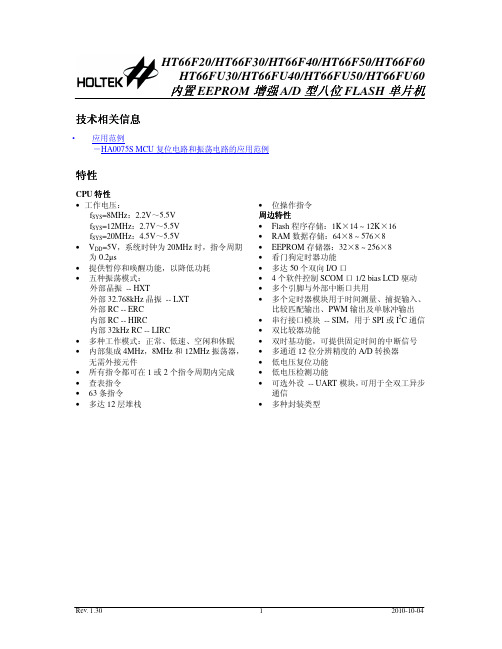
H T66F30 1 6 D IP -A /N S O P -A /S S O P -A
P A 0 /C 0 X /T P 0 _ 0 /A N 0 1 VSS&AVSS 2 P B 4 /X T 2 3 P B 3 /X T 1 4 P B 2 /O S C 2 5 P B 1 /O S C 1 6 VDD&AVDD 7 P B 0 /R E S 8
型号
外部 VDD ROM RAM EEPROM I/O 中断 A/D
TM 模块
接口 (SPI/I2C)
UART
堆栈
封装形式
HT66F20*
2.2V~ 5.5V
1K×14
64×8
32×8
18
2
12-bit×8
10-bit CTM×1 10-bit STM×1
√
√4
16DIP/NSOP/SSOP 20DIP/SOP/SSOP
在模拟特性方面,这款单片机包含一个多通道 12 位 A/D 转换器和双比较器功能。还带有多个 使用灵活的定时器模块,可提供定时功能、脉冲产生功能及 PWM 产生功能。内建完整的 SPI 和 I2C 功能,为设计者提供了一个易与外部硬件通信的接口。内部看门狗定时器、低电压复位和低电压检 测等内部保护特性,外加优秀的抗干扰和 ESD 保护性能,确保单片机在恶劣的电磁干扰环境下可靠 地运行。
fSYS=8MHz:2.2V~5.5V fSYS=12MHz:2.7V~5.5V fSYS=20MHz:4.5V~5.5V • VDD=5V,系统时钟为 20MHz 时,指令周期 为 0.2µs • 提供暂停和唤醒功能,以降低功耗 • 五种振荡模式: 外部晶振 -- HXT 外部 32.768kHz 晶振 -- LXT 外部 RC -- ERC 内部 RC -- HIRC 内部 32kHz RC -- LIRC • 多种工作模式:正常、低速、空闲和休眠 • 内部集成 4MHz,8MHz 和 12MHz 振荡器, 无需外接元件 • 所有指令都可在 1 或 2 个指令周期内完成 • 查表指令 • 63 条指令 • 多达 12 层堆栈