KTC820张力信号放大器使用说明书
放大器操作说明范文

放大器操作说明范文放大器是一种电子设备,用于增加音频信号的幅度,以便在音响系统中提供更大的音量。
它可以用于各种场合,包括家庭影院、音乐会和录音室等。
本操作手册将介绍如何正确操作放大器,以获得最佳音质和音量效果。
1.基本连接首先,确保将放大器正确连接到音源设备和扬声器。
音源设备可以是CD播放器、电视、手机等。
将音源设备的输出端通过音频线(通常是RCA或光纤电缆)连接到放大器的音频输入端。
然后,将扬声器的输入端通过扬声器线连接到放大器的扬声器输出端。
确保将正极和负极正确连接。
2.音量调节放大器有一个音量控制旋钮,通常位于正面板上。
通过转动旋钮可以调节输出音量的大小。
注意,不要将音量调得过大,以免损坏扬声器或引起听力损害。
最好从最低音量开始,逐渐增加到你所需的音量水平。
3.音调调节一些放大器还具有音调调节功能,包括低音和高音控制。
低音控制可用于增强低频音效,而高音控制可用于增强高频音效。
根据个人喜好,你可以调整这些控制旋钮以获得理想的音质。
4.输入选择如果你连接了多个音源设备到放大器,你可能需要使用输入选择功能来选择要播放的音源。
这可以通过正面板上的一个选择旋钮或遥控器上的功能按钮完成。
确保选择正确的输入通道,否则你将无法听到所需的音频。
5.安全使用在操作放大器时,有几个安全事项需要牢记。
首先,确保放大器使用的电源电压与所在地区的电压相匹配。
使用错误的电压可能会导致设备损坏或危险。
其次,避免将液体溅入放大器内部。
这可能会导致短路或其他电路故障。
另外,定期清洁放大器,以防止尘埃堆积。
使用干净的软布轻轻擦拭外壳和控制面板。
最后,当不使用放大器时,最好将其断开电源,以节省能源并避免意外触电。
6.故障排除如果你在使用放大器时遇到问题,比如没有声音、杂音等,你可以尝试以下故障排除步骤。
首先,检查所有连接是否正确。
确保音源设备和扬声器正确连接,并且连接线没有损坏。
其次,确定音量控制旋钮是否正确调节。
如果音量太小,可能听不到声音,如果音量太大,可能导致扬声器损坏。
放大器参数说明
放大器参数说明工作频率范围(F):指放大器满足各级指标的工作频率范围。
放大器实际的工作频率范围可能会大于定义的工作频率范围。
功率增益(G):指放大器输出功率和输入功率的比值,单位常用“dB”。
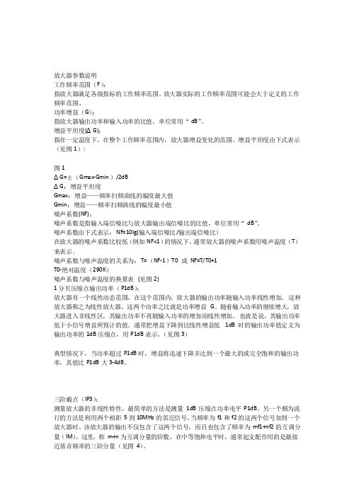
增益平坦度(ΔG):指在一定温度下,在整个工作频率范围内,放大器增益变化的范围。
增益平坦度由下式表示(见图1):图1ΔG=±(Gmax-Gmin)/2dBΔG:增益平坦度Gmax:增益——频率扫频曲线的幅度最大值Gmin:增益——频率扫频曲线的幅度最小值噪声系数(NF):噪声系数是指输入端信噪比与放大器输出端信噪比的比值,单位常用“dB”。
噪声系数由下式表示:NF=10lg(输入端信噪比/输出端信噪比)在放大器的噪声系数比较低(例如NF<1)的情况下,通常放大器的噪声系数用噪声温度(T)来表示。
噪声系数与噪声温度的关系为:T=(NF-1)T0 或NF=T/T0+1T0-绝对温度(290K)噪声系数与噪声温度的换算表(见图2)1分贝压缩点输出功率(P1dB):放大器有一个线性动态范围,在这个范围内,放大器的输出功率随输入功率线性增加。
这种放大器称之为线性放大器,这两个功率之比就是功率增益G。
随着输入功率的继续增大,放大器进入非线性区,其输出功率不再随输入功率的增加而线性增加,也就是说,其输出功率低于小信号增益所预计的值。
通常把增益下降到比线性增益低1dB时的输出功率值定义为输出功率的1dB压缩点,用P1dB表示。
(见图3)典型情况下,当功率超过P1dB时,增益将迅速下降并达到一个最大的或完全饱和的输出功率,其值比P1dB大3-4dB。
三阶截点(IP3):测量放大器的非线性特性,最简单的方法是测量1dB压缩点功率电平P1dB。
另一个颇为流行的方法是利用两个相距5到10MHz的邻近信号,当频率为f1和f2的这两个信号加到一个放大器时,该放大器的输出不仅包含了这两个信号,而且也包含了频率为mf1+nf2的互调分量(IM),这里,称m+n为互调分量的阶数。
8通道2U高密度安装音频放大器说明书

▸▸Eight channels in 2U –▸Extremely▸high▸channel▸density▸reduces▸space▸requirements▸and▸installation▸time▸▸High continuous output power of 250 W per channelat 70 V, 4 ohms, 8 ohms, and 16 ohms*▸▸All channels individually selectable for lo-Z or hi-Z Loudspeakers▸(2▸ohm▸–▸16▸ohm)▸and▸distributed▸systems▸can▸be▸connected▸to▸the▸same▸unit▸▸Bridged operation – Channel▸pairs▸bridgeable▸for▸increased▸output▸or▸for▸driving▸100▸V▸systems▸▸▸Patented output stage based on Class D topology▸▸High efficiency for lower thermal stress ▸▸General Purpose Input/Output (GPIO) – Compatible▸with▸third-party▸control▸systems▸▸NomadLink® network ready▸▸Universal Power Factor Corrected PSU with IEC inlet▸▸Efficient cooling – Dual▸variable▸speed,▸intelligent▸fans▸and▸parallel▸airflow▸over▸output▸devices▸provide▸uniform▸cooling ▸▸Comprehensive circuit protection and fault indication ▸▸Phoenix-style input connectors and barrier strip output connectorsAn Installation Amplifier without CompromiseLab.gruppen▸amplifiers▸have▸earned▸an▸enviable▸worldwide▸reputa-tion▸for▸sonic▸excellence▸and▸rock-solid▸durability▸in▸touring▸sound▸applications.▸These▸same▸qualities▸are▸now▸available▸for▸a▸broad▸range▸of▸installed▸sound▸applications▸in▸the▸C▸20:8X▸amplifier.▸By▸offering▸an▸unmatched▸combination▸of▸channel▸density,▸operating▸ef-ficiency▸and▸configuration▸flexibility,▸the▸C▸20:8X▸presents▸convincing▸performance▸and▸cost-saving▸advantages.▸Applications▸include▸pri-mary▸systems▸for▸theme▸parks,▸shopping▸malls,▸airports,▸hotels▸and▸▸restaurants▸as▸well▸as▸auxiliary▸systems▸for▸performance▸venues,▸houses▸of▸worship▸and▸numerous▸other▸installed▸sound▸applications. To▸achieve▸higher▸channel▸density▸without▸compromising▸per-formance,▸Lab.gruppen▸engineers▸developed▸a▸new▸output▸stage▸design.▸Based▸on▸a▸patented▸Class▸D▸circuit▸topology,▸these▸output▸stages▸produce▸sustained▸high▸power▸levels▸with▸very▸low▸distortion▸while▸maintaining▸efficiency▸levels▸of▸near▸90%.▸A▸new▸universal▸switching▸power▸supply▸employs▸Power▸Factor▸Correction▸(PFC)▸▸to▸stabilize▸current▸draw,▸and▸it▸accepts▸any▸mains▸voltage▸from▸▸65▸–▸265▸V▸(+/-▸10%)▸@▸50▸Hz▸or▸60▸Hz▸through▸the▸appropriate▸▸IEC▸cord.The▸C▸20:8X▸includes▸unique▸features▸which▸enable▸each▸unit▸–▸or▸even▸each▸channel▸–▸to▸be▸configured▸for▸a▸specific▸application▸or▸load▸condition.▸Input▸gain▸is▸selectable▸in▸four-channel▸groups,▸and▸a▸35▸Hz▸high▸pass▸filter▸may▸be▸inserted.▸All▸channels▸are▸bridgeable▸in▸pairs,▸and▸Lab.gruppen’s▸exclusive▸Voltage▸Peak▸Limiter▸(VPL)▸fea-ture▸allows▸each▸channel▸to▸be▸individually▸optimized▸for▸the▸reactive▸characteristics▸of▸the▸connected▸load.For▸comprehensive▸remote▸monitoring▸and▸control,▸the▸C▸20:8X▸includes▸NomadLink®▸network▸ports▸for▸connecting▸to▸an▸optional▸NLB▸60E▸NomadLink®▸Bridge▸&▸Network▸Controller▸and▸an▸Ethernet-linked▸PC.▸With▸NomadLink®,▸key▸amplifier▸parameters▸are▸displayed▸via▸DeviceControl▸software,▸and▸remote▸control▸of▸channel▸mute▸and▸power▸on/off▸is▸under▸network▸control.▸Alternatively,▸the▸GPIO▸▸facilities▸allow▸access▸to▸key▸amplifier▸functions▸via▸third-party▸▸remote▸control▸systems.▸To▸ensure▸a▸long▸and▸trouble-free▸service▸life,▸the▸C▸20:8X▸▸incorporates▸extensive▸features▸to▸safeguard▸internal▸circuits▸and▸connected▸loads.▸Protection▸and▸warning▸circuits▸prevent▸damage▸or▸service▸interruptions▸due▸to▸excessive▸current,▸DC▸at▸output,▸▸over-temperature,▸non-musical▸VHF▸(very▸high▸frequencies),▸and▸open▸load▸conditions.▸In▸addition,▸soft-start▸and▸PSU▸current▸limit-ing▸protect▸the▸mains▸supply▸from▸interruptions▸due▸to▸tripped▸circuit▸breakers▸or▸blown▸mains▸fuses.*▸Maximum▸continuous▸output▸power,▸all▸channels▸▸▸▸▸▸driven,▸VPL▸set▸at▸100▸V▸and▸Gain▸set▸at▸32▸dB ▸Auditoriums▸Performing Arts Centers▸Convention Centers▸Stadiums and Arenas▸Theme Parks▸Hotels▸Houses of Worship▸Restaurants▸Clubs▸Educational Establishments▸Boardrooms▸Museums▸Offices▸Shopping Malls▸Transportation Facilities ApplicationsC 20:8XItem no. TDS-C208X_V6GeneralNumber▸of▸channels8Peak▸total▸output▸all▸channels▸driven 2000▸WPeak▸output▸voltage▸per▸channel 100▸V▸/▸70▸Vrms Max.▸output▸current▸per▸channel 8▸Arms Max. Output Power 16 ohms 8 ohms 4 ohms 2 ohms Hi-ZPer▸ch.▸(all▸ch.’s▸driven)250▸W 250▸W 250▸W 125▸W 250▸W▸(70▸Vrms▸/▸100▸V▸peak)Bridged▸per▸ch.500▸W500▸W250▸Wn.r.500▸W▸(140▸Vrms▸/▸200▸V▸peak)Performance with Gain: 32 dB and VPL: 100 V THD▸20▸Hz▸-▸20▸kHz▸for▸1▸W<0.1%THD▸at▸1▸kHz▸and▸1▸dB▸below▸clipping <0.05%Signal▸To▸Noise▸Ratio>112▸dBA Channel▸separation▸(Crosstalk)▸at▸1▸kHz>70▸dBFrequency▸response▸(1▸W▸into▸8▸ohms)▸+0/-3▸dB 6.8▸Hz▸-▸34▸kHz Input▸impedance20▸kOhm Input▸Common▸Mode▸Rejection,▸CMR 50▸dB Output▸impedance▸@▸100▸Hz48▸mOhmVoltage Peak Limiter (VPL), max. peak output VPL,▸selectable▸per▸ch.▸(V)▸3)100,▸63,▸45,▸32▸V VPL,▸selectable▸when▸bridged▸(V)▸3)▸1)200,▸126,▸90,▸64▸V Voltage▸Peak▸Limiter▸mode▸(per▸ch.)Hard▸/▸SoftGain and LevelAmplifier▸gain▸selectable▸(all▸channels)▸1)▸–▸rear-panel▸switches 29,▸32,▸35,▸38▸dBDefault▸gain32▸dBLevel▸adjustment▸(per▸ch.)Front-panel▸potentiometer,▸21▸position▸detented▸from▸-inf▸to▸0▸dB,▸hidden▸behind▸security▸panel/dust▸filter▸grilleConnectors and switches Input▸connectors▸(per▸ch.)3-pin▸Phoenix,▸electronically▸balanced Output▸connectors▸(per▸ch.)Barrier▸strip▸2-pole▸screw▸terminals Output▸bridge▸mode A+B,▸C+D,▸E+F ,▸G+H,▸inputs▸A,▸C,▸E,▸G▸are▸signal▸source High▸pass▸filterFixed▸at▸35▸Hz,▸switchable▸per▸channelNomadLink ®▸network On▸board,▸2▸x▸RJ45▸connectors,▸IN▸and▸OUT Intelligent▸fans▸(on/off)Y es,▸depending▸on▸presence▸of▸output▸signal Power▸on/off▸and▸Remote▸enable▸on/off Individual▸switches▸on▸front-panelCoolingTwo▸fans,▸front-to-rear▸airflow,▸temperature▸controlled▸speed General▸Purpose▸Outputs▸(GPO)Contact▸Closure▸types,▸2-pole▸Phoenix General▸Purpose▸Inputs▸(GPI)Contact▸Closure▸types,▸2-pole▸PhoenixFront-panel indicators Common NomadLink ®▸Network;▸Power▸Average▸Limiter▸(PAL)▸2);▸Power▸on▸Per▸channelSignal▸present▸/▸High-impedance;▸Voltage▸Peak▸Limiter▸(VPL);▸Current▸Peak▸Limiter▸(CPL):▸Very▸High▸Frequency▸(VHF);▸High▸temperature;▸Fault;▸MutePowerOperating▸voltage,▸230▸V▸/▸115▸V▸nominal 65-265▸V Minimum▸power-up▸voltage,▸230▸V▸/▸115▸V 80▸V Power▸Average▸Limiter▸(PAL)▸2)YesSoft▸start▸/▸Inrush▸current▸draw Yes▸/▸max.▸5▸A Mains▸connector IEC▸InletDimensions (W/H/D)W:▸483▸mm▸(19”),▸H:▸88▸mm▸(2▸U),▸D:▸343▸mm▸(13.5”)Weight 8.5▸kg▸(18.75▸lbs.)FinishBlack▸painted▸steel▸chassis▸with▸gray▸painted▸steel▸front ApprovalsCE,▸ANSI/UL▸60065▸(ETL),▸CSA▸C22.2▸NO.▸60065,▸FCC▸▸Note 1):▸Automatic▸-6▸dB▸gain▸compensation▸when▸bridging▸channels.▸Ch.’s▸A+B▸and/or▸C+D,▸E+F,▸G+H,▸can▸be▸bridged▸individually.▸Note 2):▸PAL▸can▸reduce▸the▸maximum▸output▸power▸to▸keep▸the▸power▸supply▸operating▸safely,▸and/or▸to▸prevent▸excessive▸current▸draw▸tripping▸the▸mains▸breaker.▸▸▸▸▸Refer▸to▸Operation▸Manual.▸Note 3):▸For▸sine▸waves,▸peak▸voltage▸output▸values▸translate▸to▸Vrms▸with▸the▸formula▸V/1.41▸=▸Vrms.▸E.g.▸100▸V▸peak▸equals▸app.▸70▸Vrms.▸▸Hence,▸outputs▸can▸be▸set▸for▸high-impedance▸loads▸without▸requiring▸a▸transformer. All specifications are subject to change without notice.L a b .g r u p p e n a b ▸ S w e d e ni n t e r n a t i o n a L c o n t a c t ▸ i n f o @L a b g r u p p e n .c o m | u S & c a n a d a c o n t a c t ▸ i n f o @t c g -a m e r i c a S .c o mw w w .l a b g r u p p e n .c o mSpecifications C 20:8X。
放大器操作说明

放大器操作说明一、放大器的设置1.打开Nexus 元件的电源并使Nexus 元件初始化。
2.如果Nexus 元件没有显示主菜单,则应按底下的“Home ”键,直到出现主菜单。
在主菜单上应有诸如“Amplifier Set -up (放大器设置)”,“Transducer Set -up (传感器设置)”等选项。
如照片1所示:3.滚动到“Amplifier Set -up (放大器设置)”并按底下的“↙”一次。
如照片2所示:照片 1照片 24.在“Amplifier Set -up (放大器设置)”菜单下,应通过在底下箭头键来滚动到“Hz ”,以确保“Hz ”显示加亮。
一旦“Hz ”显示加亮,则按 “Ch ↓”键。
随后应用“+”和“-”按键来设置Hz (频率)为A 。
一旦通道1设置为A ,则应按 “Ch ↓”键,并对通道2,3和4作同样的工作。
如果是2通道Nexus 元件,那么只需要编程两个通道。
当所有通道设置为A 时,按“Home ”键返回。
如照片3所示:然后,用“→”键移动到“Out (输出)”。
一旦“Out (输出)”被显示加亮,使用“Ch ↓”键和“+”与“-”键把每个通道都设置为316mV/Pa 。
当所有通道都设置为316mV/Pa 后,按“Home ”键返回。
最后回顾一下菜单,确保所有的通道都被分别设置在A 下,“Out ”输出为316 mV/Pa 。
当所有设置项都设置正确后,按“Home ”键返回。
如照片4所示:照片 3滚动到“Transducer Set -up (传感器设置)”下并按底下的“↙”一次。
如照片5所示:(此步可以省略,因为麦克风的灵敏度是自动识别的不用设置)编辑此菜单需要声学传感器的校准数值。
当得到校准数值后,滚动到“Sensitivity (灵敏度)”并按“Ch ↓”键。
如照片6所示:照片 4照片 5随后将处在显示加亮的十进制数值的通道#1。
用“+”与“-”键把此数值设置为对应于此通道/声学传感器的校准/灵敏度数值。
新硬件820说明书v3.1最新资料
尊敬的用户:欢迎使用本公司的产品。
在使用本产品前,请认真阅读随机附带的《说明书》。
本说明书重点介绍NHZK820型皮带秤仪表各项功能及操作,使用中遇到问题,请随时与本公司联系。
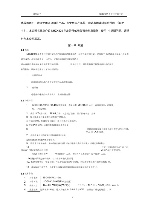
第一章概述1.1概述NHZK820型皮带秤控制仪表是专门针对皮带秤设计的一种高性能控制仪表,采用抗干扰措施和多项单片机最新研究成果,具有功能强大、体积小、可靠性高和适应性强等特点。
适合各种形式和各种量程的皮带秤的控制,用于绞刀秤、圆盘秤和转子秤等多种形式的动态秤的控制。
该仪表适用于以下的控制系统:1. 定量给料机通过控制给料机的皮带速度或预给料控制流量。
2. 皮带秤通过皮带速度控制皮带负荷,从而控制流量。
1.2功能特点1. 标准的RS-232和RS-485通讯功能,遵循标准MODBUS协议,通讯速度快,可靠性高。
(可选功能)2. 采用LCD显示器,128*64点阵,汉字提示信息,显示信息丰富、直观。
3. 输入输出接口采用多种硬件抗干扰技术。
4•可通过键盘、外部信号(端口)和上位机对仪表操作。
5•智能PID调节。
并且控制周期可以任意设定。
6. 可以通过仪表接口和通讯接口等方式与上位机、PLC或DCS连接。
7. 具有流量控制和定量控制两种控制方式。
&具有调速和恒速两种工作模式。
9. 设有累计脉冲输出,脉冲的宽度和当量(每个脉冲代表的物料量)可通过参数设定。
10. 仪表“流量设定方式”和“启动方式”可以分别通过对应的DI输入信号进行切换, 当DI有效时即为“外部接口”方式,否则为“仪表键盘”或“通讯”方式。
11•关键参数设定密码保护,以防止非专业人员误用。
12. 快捷参数备份、恢复功能。
可备份仪表内部所有参数,当仪表参数出现问题时重新恢复。
13. 具有容积工作方式。
当荷重传感器出现问题时仪表可切换到容积工作方式。
1.3技术参数1.工作电源: 85-265VAC /10W。
2.工作环境: -10-50 C /5-90%RH(无结露)。
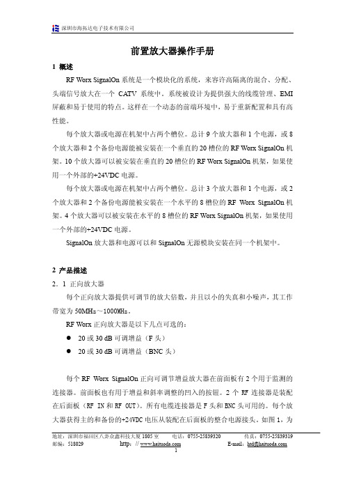
泰德系列光纤放大器说明书

TED SERIESINSTRUCTION MANUALCONTROLS1 and2 OUTPUT LEDsThe yellow LEDs indicate the status of the corresponding outputs duringthe normal operating status.1 and2 READY/ERROR LEDs (bicolour)The bicoloured LEDs are permantely green indicate that the receivedsignal guarantees a stable output status.The alternative blinking of the LEDs indicate a wrong setting condition.Please refer to the “SETTING” paragraph for correct for setup procedureindications.SET1 and SET2 PUSHBUTTONA long pressure on the pushbutton activates the self-setting procedureof the corresponding channels.INSTALLATIONprotection lid can be removedopening it completely and pullingit slightly.Mount the sensor on a DIN rail orthanks to the fixing holes usingscrews (M3x20 or longer) withwashers.Installation of the fibre-optics:Press the lock pushbutton and keep it pressed until all the fibres hasbeen completely inserted.Insert the fibres in the corresponding holes as described in thedimension drawing.The transparent CLEAR-LOCK TM fixing block allows to easily check thatthe fibres are close to the photoelements.The insertion resistance is due to the O-ring seal; please insert the fibresfor about 6mm deeper until they touch the photoelements.CONNECTIONSOUTPUT 1OUTPUT 20 VM8 CONNECTOR12 … 24 VdcOUTPUT 10 VOUTPUT 2(WHITE)(BROWN)(BLUE)(BLACK)+-TECHNICAL DATAPower supply: 12 … 24 Vdc±10% (reverse polarity protection)Ripple: 2 Vpp max.Current consumption(output current excluded): 60 mAOutputs: NPN (TED-x-N) or PNP (TED-x-P)Output current: 100 mA max. at 25 °C derating –2 mA/°COutput saturation voltage: 1.2 V max.Response time: 250 μs max.Indicators: 2 OUTPUT LEDs (YELLOW) and 2 READY/ERROR LEDs (RED/GREEN)Setting: 2 SET1 and SET2 pushbuttonsData retention: non volatile EEPROM memoryOperating temperature: -10 … 55 °CStorage temperature: -25 … 70 °CElectrical shock protection: Class 2Operating distance (typical values): proximity (with OF-xx-ST fibre-optic) 0 … 70 mmthrough beam (with OF-xx-ST fibre-optic) 0 … 280 mmEmission type: red (630 nm)Ambient light rejection: according to EN 60947-5-2Vibrations: 0.5 mm amplitude, 10 … 55 Hz frequency, for every axis (EN60068-2-6)DARK/LIGHT selection: 11 ms (30 G) 6 shock for every axis (EN60068-2-27)Housing: PolycarbonateMechanical protection: IP65Connections: 2 m cable ∅ 4.5 mm / M8-4 pole connectorWeight: 115 g. max. cable vers. / 30 g. max. connector vers.SETTINGEASY TOUCH™The sensor uses the patent-covered EASY TOUCH™ technology thatallows a rapid and safe self-setting of the product.Two different setting possibilities are available:- EASY TOUCH™; a long pressure of the SET pushbutton allows self-setting.- FINE DETECTION; to be used only in particularly critical conditions.This setting procedure is used only when the EASY TOUCH™ is notsufficient.TED settingThe EASY TOUCH™ foresees the LIGHT operating mode.Thus using proximity fibres, the output is closed and the output LED isON when the object is detected.Using through beam fibres, the output is closed and the output LED isON when the object does not interrupt the beam (i.e. the object is notdetected).- EASY TOUCH™ (standard detection)Place the object to detect either in front of the proximity fibres withinthe operating range, or in the middle of the through beam fibres.Press the SET1 pushbutton (or SET2 for the second channel).Keep the pushbutton pressed until the signalling LED turns green andthe READY/ERROR LED turns off.Release the SET pushbutton. The sensor is now ready to detect theobject.- Fine detectionThis mode offers an improved detection precision. The sensor canfunction either in the DARK operating or in the LIGHT operatingmode.1) Place the object to detect in front of the proximity fibres within theoperating distance, or in the middle of the through beam fibres.Press the SET1 pushbutton (or SET2 for the second channel) andkeep it pressed until the READY/ERROR LED turns on.Keep it pressed until the LED turns off and maintain the pressureuntil the signalling LED begins to blink green.The sensor is now ready for the second setting.2) Remove the object to detect and press the SET pushbutton againuntil the READY/ERROR LED turns on.The sensor is now ready to detect very precisely the pre-set object.If the READY/ERROR LED begins to blink red and green, thesetting has failed, as the contrast is insufficient. Thus the settingprocedure has to be repeated.Following this setting procedure, the sensor functions in the LIGHTmode with proximity fibres and in the DARK mode with through beamfibres. To set the sensor in the DARK mode for proximity or LIGHTmode for through beam, invert the sequence given above.The operative DARK/LIGHT mode is automatically selected by thesensor when is used as contrast sensor.‘OR’ function by means of parallel output connectionThe 1 and 2 outputs can be connected together in parallel, obtainingan ‘OR’ function; this means that the common output is activatedeven if just one of the two fibres has detected the object.DECLARATION OF CONFORMITYWe DATALOGIC AUTOMATION declare under our sole responsibilitythat these products are conform to the 2004/108/CE and successiveamendments.WARRANTYDATALOGIC AUTOMATION warrants its products to be free fromdefects.DATALOGIC AUTOMATION will repair or replace, free of charge, anyproduct found to be defective during the warranty period of 36 monthsfrom the manufacturing date.This warranty does not cover damage or liability deriving from theimproper application of DATALOGIC AUTOMATION products.DATALOGIC AUTOMATIONVia Lavino 265 - 40050 Monte S.Pietro - Bologna – ItalyTel: +39 051 6765611 - Fax: +39 051 6759324e-mail:********************************Datalogic and the Datalogic logo are registered trademarks of DatalogicS.p.A. in many countries, including the U.S.A. and the E.U.826000992Rev.C© Copyright Datalogic 2008-2010。
放大器中文操作手册
理想输入电平
20dBmV 每频道
10dBmV 每频道
增益电平
20dB 最大
30dB 最大
反射损耗,所有端 -19.0dB, 50MHz~870 MHz -18.0dB, 50MHz~870 MHz
口(最大增益)
-16.5dB, 870MHz~1000 MHz -15.0dB, 870MHz~1000 MHz
环境的
工作温度
0℃~+50℃(+32℉~+122℉)
平坦度为
存储温度
-40℃~+70℃(-40℉~+158℉)
+0.5dB, 周 围 环
境从 25℃
存储湿度
20~90%
非凝固
地址:深圳市福田区八卦众鑫科技大厦 1805 室 电话:0755-25839320
邮编:518029
http://
3 操作 3.1 增益调整
放大器的增益可以通过使用模块前面板上的按钮来调整。这里有 2 个按钮, 标记为“+”和“-”,分别为增益增加和减少。“+”按钮增加增益以大约 0.5dB 为步径,“-”按钮减少增益以大约 0.5dB 为步径。这里总共有 20 个增加步径, 相当于大约 10dB。增益可以按适合的键快速地升降在一秒钟这内。
7
传真:0755-25839319 E-mail:htd@
深圳市海拓达电子技术有限公司
参数 功耗
表 3 可调增益放大器电子参数
20dB 正向放大器
30dB 正向放大器
17.0W 最大
17.0W 最大
带宽
50~1000MHz
50~1000MHz
阻抗 可调的 RF 增益
增大器的使用方法

增大器的使用方法
使用增大器的方法取决于具体的设备和应用场景。
以下是一般情况下增大器的使用方法:
1. 连接电源:将增大器的电源线连接到适配器或电源插座上,并打开电源开关。
2. 输入源连接:将需要放大的音频信号源连接到增大器的输入端口。
通常增大器会有多个输入通道,可以根据需求选择连接。
3. 确定增益:根据所需的放大程度调节增大器的增益控制器。
增益控制器通常是旋钮或滑动条,通过适当调整增益来获得所需的声音大小。
4. 连接扬声器:将扬声器的线缆连接到增大器的输出端口。
确保连接正确,以避免损坏设备。
5. 调整音量:根据需要调整扬声器的音量控制器,以获得适当音量水平。
6. 测试和微调:在连接好扬声器后,播放音乐或其他音频源,以检查声音质量和音量是否满足要求。
根据实际情况微调增益和音量。
请注意,具体的增大器使用方法可能因品牌和型号而有所不同。
因此,在使用之前应仔细阅读设备的用户手册或参考相关的使用指南。
- 1、下载文档前请自行甄别文档内容的完整性,平台不提供额外的编辑、内容补充、找答案等附加服务。
- 2、"仅部分预览"的文档,不可在线预览部分如存在完整性等问题,可反馈申请退款(可完整预览的文档不适用该条件!)。
- 3、如文档侵犯您的权益,请联系客服反馈,我们会尽快为您处理(人工客服工作时间:9:00-18:30)。
1、产品概要
KTC820张力信号放大器是由高精度ADC 、DAC 及微处理器构成,能把张力传
感器微弱的信号放大为0~10V 和4~20mA 的标准信号,信号处理过程全数字化,无需电位器调整,信号稳定无漂移,是采集张力信号的理想仪器,具有以下特点: 标定过程只需两个步骤,操作简单;
全数字化处理,无电位器调整,稳定可靠,无漂移; 实时显示测量到的张力值; 支持0~10V 模拟量输出; 支持4~20mA 电流输出;
支持Modbus RTU 数据通讯,连接PLC 简单方便,确保信号无损传输; 可设置张力报警输出(继电器常开/常闭触电输出); 可调输出比率; 嵌入式安装;
2、接线方式
3、操作说明
3.1、操作概述
放大器上方一共有4个按键,分别为SET 、ESC 、DOWN 、UP 按键。
放大器
上电后为张力监视状态,此时左上方数码管显示现在的张力测量值。
长按SETUP 键约3秒,进入设置菜单,现在版本可设置的项目为:
右张力传感器
RS485
N.C.N.C.L 左张力
传感器
AL-N.O.N.C.N.C.
485B AL-N.C.N
AC180~220V
485A AL-COM N.C.2112
11109876543
3.3
请根据您的接线来设置本参数,如果单独接一个传感器且接在GRL和YEL上,
GRR 和YER
3.4
传感器安装后,为了去除导辊和轴承等毛重对张力测量的影响,需要进行零张力标定,此时在安装完导辊,不通过材料的状态下进行。
Setup键进入,此时屏幕上闪烁显示0,此时再长按Setup键3秒,屏幕将会快速闪烁显示---,稍等一下便完成校准。
有一快捷进入方法,就是在张力监控状态下,长按Setup键5秒,便可自动进行零张力标定。
3.5(满量程标定,跨度标定)
材料张力施加在传感器上的负载因传感器安装方向以及材料通过角度(包角)的不同而异,所以必须对此进行校正,进行满量程标定(跨度标定)。
标定步骤如下:
Setup 键进入;
如下图所示,按走料方向装上绳子,绳子一端固定,另一端悬挂已知重量的
物体,把该物体的重量输入到放大器中;
长按Setup 键3秒,放大器开始进行标定,此时快速闪烁---,稍等一下即可
完成标定; 3.6
该参数设定零张力时所对应的输出电压,可设置为0~10V ; 3.7
该参数设定当张力等于满量程(满量程标定所设置的挂重值)时所对应的输出电压,可设置为0~10V 。
该参数方便用户调整输出比率。
例如,满量程标定时侧挂重量为10KG ,但需要检测的张力最大为50KG ,那么可设置该参数为2.00V ,即是10KG 张力时输出2.00V ,50KG 张力时输出10.00V ; 3.8、参数
该参数设定零张力时所对应的输出电流,可设置为4~20mA ; 3.9参数
该参数设定当张力等于满量程(满量程标定所设置的挂重值)时所对应的输出电
悬挂已知重量的物体,把该物体的重量输入到满量程标定的参数里,单位为KG
绳子一端固定
流,可设置为4~20mA。
该参数方便用户调整输出比率。
例如,满量程标定时的挂重量为10KG,但需要检测的张力最大为50KG,那么可设置该参数为7.2mA,即是10KG张力时输出7.2mA,50KG张力时输出20mA。
3.10
该参数设定滤波器的滤波时间长度,数值越大输出越稳定,但反应越慢。
数值越小反应越快,但会因为机器运转时的震动而造成测量值的跳动。
3.11
可设置4.8K(4800bps)、9.6K(9600bps)、19.2K(19200bps)。
3.12
通讯地址(站号)。
可设置1~99。