低速双燃料发动机技术数据
双燃料发动机

二冲程机
2. 低压双燃料发动机(DF) 柴油引燃 燃气进口在扫气口上方冲程中部的位置 奥托循环 满足IMO Tier Ⅲ要求 效率大于四冲程机
二冲程机
三.典型双燃料发动机
1. MAN ME-GI(低速机) 2. Wärtsilä50DF(中速机)
1. ME-GI 电控双燃料柴油机
主燃油系统采用传统方式由凸ቤተ መጻሕፍቲ ባይዱ轮轴驱动高压油泵产生150MPa 的高压油,送至大孔; 点火油由点火油泵单元升压至 90Mpa送至小孔
Wärtsilä 50DF
供气系统
Wärtsilä 50DF
Pe与空燃比
启动模式
运行模式
双燃料发动机简介
2013.4.10
目录
一.前言 二.双燃料发动机的分类 三.典型双燃料发动机的简介
一. 双燃料发动机的发展动力
1. 海事环保法规的要求
2. LNG作为清洁能源的优势
二.双燃料发动机的分类
1. 高压燃气喷射发动机(Gas Diesel engine, GD) 2. 电火花点火的气体发动机(Spark ignited Gas engine, SG) 3. 低压双燃料发动机(Dual Fuel engine, DF)
四冲程机
(一)四冲程机 1. 高压燃气喷射发动机(GD或GI) 可在不同燃气/柴油比例下运行,或可仅燃用柴油 可燃气体在压缩终点喷入气缸 燃气进气/喷射压力高,350bar 狄赛尔循环 真正的“双燃
料”发动机
2. 电火花点火的气体发动机(SG) 只能使用气体燃料 燃气与空气一起压缩,电火花点火 燃气进机压力低,<5bar 奥托循环 单燃料发动机
ME-GI,即ME engine with gas injection。 MAN B&W公司于 2005年在ME柴油机 的基础上推出的电子 控制双燃料柴油机。
双燃料发动机

Wärtsilä 50DF
供气系统
Pe与空燃比
启动模式
运行模式
V3
V5
ME-GI
燃气系统
燃气喷射
ME-GI
燃料比例变化
作主机时可以在25%负荷以上时,从 100%燃油到95%天然气+5%燃油之间, 燃气和燃油可进行任意比例切换。但 无法满足Tier Ⅲ 的要求,除非使用 EGR或SCR
Wärtsilä 50DF
2. Wärtsilä 50DF 中速机
2006年,50DF发动机应用在第一艘LNG船上
Wärtsilä 50DF
至2012年2月,共720台DF发动机(含陆用),累计运行 >5,000,000小时
Wärtsilä 50DF
点火油和主燃油系统
Wärtsilä 50DF
点火油和主燃油系统
主燃油系统采用传统方式由凸 轮轴驱动高压油泵产生150MPa 的高压油,送至大孔;
四冲程机
柴油模式可使用重油作燃油,柴油依然作点火油
只有空气被压缩 狄赛尔循环 双燃料发动机
二冲程机
(二)二冲程机
1. 燃气发动机(GD或GI) 狄赛尔循环 不满足IMO Tier Ⅲ要求 需要加后处理装置
二冲程机
2. 低压双燃料发动机(DF)
柴油引燃 燃气进口在扫气口上方冲程中部的位置 奥托循环 满足IMO Tier Ⅲ要求 效率大于四冲程机
双燃料发动机简介
2013.4.10
目 录
一.前言 二.双燃料发动机的分类
三.典型双燃料发动机的简介
一.双燃料发动机的发展动力
1. 海事环保法规的要求
柴油 甲醇双燃料发动机主要参数
附录A(规范性附录)柴油/甲醇双燃料发动机主要参数A.1发动机结构参数生产企业:型号:型式(系指冲程数、冷却方式、气缸排列方式、燃烧室型式、燃料供给方式、是否增压、是否带中冷器、是否带催化器等)3)气缸数:缸径/行程:mm/mm总排量:L压缩比:着火火顺序:旋转方向:A.2发动机性能参数额定功率:kW额定功率转速1):r/min最大扭矩1):N·m最大扭矩转速1):r/min怠速转速1):r/min额定工况柴油消耗量:kg/h额定工况甲醇消耗量:kg/h额定工况当量燃料消耗率:g/kW·h最低当量燃料消耗率:g/kW·h最高热效率:%最高平均有效压力:bar最高爆发压力:MPa排放水平:A.3生产企业应给定的参数A.3.1燃料A.3.1.1柴油推荐的柴油规格:低热值1):kJ/kgA.3.1.2甲醇推荐的甲醇燃料规格:7低热值1):kJ/kgA.3.2机油规格:(夏季)(冬季)A.3.3规定的温度冷却水出口最高温度:K或℃最高排气温度:K或℃机油温度:最高K或℃最低K或℃柴油温度:最高K或℃最低K或℃甲醇温度:min~max K或℃进气温升(压气机出气口与环境的温差)2):max K或℃甲醇系统部件工作环境温度:min~max K或℃冷起动最低环境温度:K或℃A.3.4规定的压力机油压力:min~max MPa甲醇喷射压力:MPa压力变化允差:MPa柴油喷射压力:MPa排气背压:min~max kPa中冷器2)压力降:max kPaA.3.5其它额定工况时的空气消耗量:kg/h全负荷下活塞最大漏气量:L/min额定工况机油燃料消耗比:%外形尺寸(长×宽×高):mm净质量(不包括油、水、散热器及传动装置):kg总质量(包括散热器、底座及传动装置):kgA.4增压中冷系统2)A.4.1增压器生产企业:型号:特征描述(是否为水冷中间壳,是否带废气排放阀等):A.4.2中冷系统2)生产企业:型号:特征描述(水冷或空冷、材质等):A.5配气系统进气门:上止点前(°CA)开,下止点后(°CA)关8最大升程:mm;间隙:冷热mm 排气门:下止点前(°CA)开,上止点后(°CA)关最大升程:mm;间隙:冷热mmA.6空气污染防治措施2)A.6.1废气再循环(EGR)2)生产企业:型号:特性描述(流量、EGR控制方式、冷却方式、EGR率描述等):A.6.2选择性催化还原(SCR)2)生产企业:型号:特性描述:A.6.3催化转化器(DOC)2)生产企业:型号:尺寸、形状和容积:安装位置(在排气管路中的位置):安装方式描述(如独立安装、并联安装、串联安装):贵金属总含量:载体(结构和材料):孔密度:A.6.4柴油颗粒捕集器(DPF)2)生产企业:型号:尺寸、形状、容积:型式和结构:过滤效率:贵金属总含量:载体(结构和材料):孔密度:再生方法描述:A.6.5其它系统2)种类和作用:A.7冷却系统9A.7.1冷却液种类及特性:A.7.2水泵2)型号:特性:传动比:A.7.3节温器型号:初开冷却液温度:℃;全开冷却液温度:℃;升程:mmA.8润滑系统A.8.1机油泵2)型号:A.8.2机油冷却器2)型号:A.9柴油供给系统A.9.1系统描述特征:工作原理:A.9.2喷油泵生产企业:型号:泵端压力:MPa静态喷油正时:喷油提前曲线:校准方法:A.9.3调速器生产企业:型号:减油点:全负荷开始减油点转速:r/min 最高空车转速:r/min怠速转速:r/minA.9.4高压油管2)长度:内径:A.9.5共轨管2)生产企业:型号:工作轨压:MPa10A.9.6喷油器生产企业:型号:开启压力:MPa开启压力特性曲线:A.9.7冷起动系统生产企业:型号:描述:A.9.8辅助起动装置2)生产企业:型号:描述:A.10甲醇供给系统A.10.1甲醇喷射装置A.10.1.1单点喷射式2)A.10.1.1.1喷嘴数量:型号:可能的调节:工作压力:kPa1)材质:工作电压:V额定工况流量:kg/h(或提供流量-压力差函数曲线)A.10.1.1.2甲醇轨型号:可能的调节:工作压力:kPa1)材质:附属装置:A.10.1.1.3其它装置A.10.1.2多点喷射式2)A.10.1.2.1喷嘴数量:型号:工作压力:kPa1)材质:工作电压:V额定工况流量:kg/h(或提供流量-压力差函数曲线)A.10.1.2.2甲醇轨型号:工作压力:kPa1)材质:附属装置:A.10.1.2.3其它装置11A.10.2甲醇压力调节器型号:数量:工作压力:kPa1)材质:A.10.3甲醇过滤器型号:滤清能力:工作压力:kPa1)材质:A.10.4甲醇泵型式(直流或交流,有刷或无刷):型号:特性:工作压力:kPa1)材质:A.10.5甲醇液位计型号:工作电压:V材质:A.10.6甲醇管型号:材质:内径:mm外径:mm A.11电控系统A.11.1发动机电控单元型号:系统电压:V接地极:A.11.2甲醇电控单元2)型号:系统电压:V接地极:A.11.3传感器A.11.3.1油门位置传感器2)型号:A.11.3.2节气门位置传感器2)型号:A.11.3.3甲醇流量传感器2)型号:工作压力1):kPa材质:12安装尺寸:A.11.3.4气体温度传感器2)型号:安装尺寸:数量:A.11.3.5水温传感器型号:安装尺寸:数量:A.11.3.6转速传感器型号:安装尺寸:数量:A.11.3.7压力传感器2)型号:安装尺寸:数量:A.11.3.8绝对压力传感器2)型号:安装尺寸:数量:A.11.3.9相位传感器2)型号:安装尺寸:数量:A.11.4执行器A.11.4.1节气门2)型号:A.11.4.2高压EGR阀2)型号:A.11.4.3低压EGR阀2)型号:A.11.4.4排气背压阀2)型号:A.11.4.5怠速旁通控制阀2)型号:A.11.4.6废气旁通控制阀2)13型号:A.12电气系统A.12.1发电机输出电压:型号:A.12.2起动机输入电压:型号:A.13其它(详细目录,必要时简要说明)注1):应给定范围或公差。
双燃料技术介绍
温度传感器
作用:ECU采集发动机温度的主 要传感器,是判断发动机状态的 信息来源,是ECU系统能够正常工 作的必要条件。
。 。安装位置:发动机的排气管上
。
混合器
作用:让天然气和空气在混合 器内混合。 安装位置:安装在发动机进气 歧管上,位于中冷器出口与进气 歧管之间。
限油盒
作用:限油盒就是靠电子信号 来限定转速和油量的。 安装位置:安装在驾驶室内的仪 表盘下面。
系统正常工作时,由原柴油供给系统提供固定量的柴油。当负荷 增加时通过增加天然气的喷气量来实现发动机输出功率和扭矩的增加 。
“柴油-LNG”混烧原理图
“柴油-CNG”混烧原理图
3、主要零部件
传感器
传感器 主要有油耗仪、压力传感器、转 速传感器、温度传感器
系统主要部件
ECU
ECU电控单元通过监测采集车辆发动机实 时作状况信号,控制双燃料系统启停和 提供适合的燃料供给。
10
转速传感器
定义:转速传感器是一 种磁电式传感器,利用电磁感 应原理,将输入运动速度变换 成正弦波信号输出。 作用:ECU采集发动机 转速的主要传感器,是判断发 动机状态的信息来源,是ECU 系统能够正常工作的必要条件。 安装位置:采用原发动 机转速(曲轴)传感器的信号 或者在发电机处安装齿轮盘用 来测量转速。
实际耗油量(L) 44.4
实际百公里耗油量 (L/100km)
22.2
耗气量 (kg)
25.6
燃料费用 (元)
462
燃料节省 率(%)
22.37
总耗 比
0.96
燃料替代 率(%)
46.89
经济性 0.67
3、重汽豪瀚J7B38
双燃料船用发动机气体燃料消耗量计算DF engine gas fuel consumption
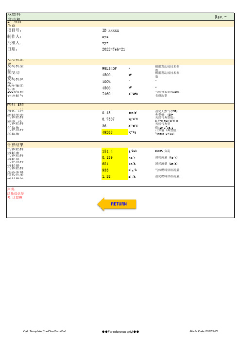
双燃料发动机Rev.-
1. 项目
信息
项目号:ID xxxxx
制作人:xyz
批准人:xyz
日期:2022-Feb-21发动机配
置
发动机型号:W9L34DF-根据发动机技术参
数
额度功率:4500kW根据发动机技术参
数
发动机负
荷:100%--
实际输出
功率:4500kW-
100%负荷发动机气7460kJ/kWh气体设备需按100%
负荷选型
Fuel gas
properti 液化气体
燃料的密0.43ton/m³液化天然气(LNG)
典型值: 430-
气体燃料密度 (00.7307kg/m³N天然气典型值:
0.7-0.9kg/m³N @
气体燃料低热值36MJ/m³N天然气典型
值:29.3~39.8
气体燃料低热值49268kJ/kg计算值 (典型值
~49620 kJ/kg)
计算结果
气体燃料消耗率151.4g/kwh@100% 负荷
气体燃料消耗量0.189kg/s消耗流量 (kg/s)
气体燃料消耗量681kg/h消耗流量 (kg/h)
气体燃料供给流量933m³N/h气体燃料供给流量
液化状态
燃料供给
1.58m³/h液化燃料供给流量
声明:
结果仅供参
考,计算模
RETURN
Cal. Templete:FuelGasConsCal●●For reference only!●●Made Date:2022/2/21。
低速双燃料发动机技术分析
低速双燃料发动机技术分析随着全球油价持续走高以及越来越严格得排放限制,船东越来越重视船舶得经济性与清洁环保。
虽然市场上也能瞧到燃料电池、氢燃料动力、混合动力等技术,但目前最为成熟与具有经济性得替代能源无疑仍然就是天然气。
《国际气体动力船舶规则》(IGF Code)得日趋成熟,使天然气燃料动力船越来越受关注,不仅在渡轮、拖轮等短程小船中得到应用,在国际航行得天然气运输船、集装箱船、油船、大型矿砂船等领域也得以推广。
天然气作为船舶燃料起初主要用于沿海渡轮等小型船舶,这一方面就是由于燃料舱尺寸限制了双燃料发动机在远洋船得使用,另一方面也就是因为远洋船所用得电力推进效率低于低速柴油机,不具备经济性。
随着油价与天然气价格差扩大及排放限制,MAN Diesel & Turbo已推出ME-GI系列低速双燃料发动机,Wartsila公司也推出Flex-DF低速发动机,两大垄断厂商得重磅产品得推出,将会在低速柴油机主宰得远洋船舶市场上取得明显得竞争优势,改变当前双燃料发动机得市场格局,使气体动力船走向远洋成为可能。
本文介绍了气体燃料动力系统发展得趋势,以第三方视角,对比高低压低速双燃料发动机得特点与优劣,分析其经济性与应用前景,供船东选型参考。
低速双燃料发动机前景1、天然气燃料得安全性与经济性安全性与经济性就是决定清洁能源技术能否广为应用得最关键得两个方面。
首先,气体燃料得使用已经有几十年得经验,人们不断摸索完善燃气在船上安全应用得方案,各大船级社制定了自己得规范。
I MO也在MSC285(86)临时导则得基础上修订了IGC Code,并将很快推出IGF Code,双燃料动力装置得安全性已得到认可、另一方面,风险分析与模拟技术得使用,使燃气动力系统得到了适当得简化,单一气体发动机也得以使用、但对于大型远洋船舶,风险分析表明动力系统得可靠性非常重要,在一定时期内,双燃料系统仍将就是不可替代得、其次,在经济性方面,燃气与燃油得价格差就是影响气体燃料动力装置经济性得关键因素。
双燃料发动机
双燃料发动机的技术分析双燃料发动机的技术分双燃料发动机的技术分析的技术摘要:简要介绍了气体燃料发动机的主要特点是缓解能源危机和降低摘要有害物排放,按使用燃料的特点可分为单一燃料、两用燃料和双燃料发动机,双燃料发动机是气体燃料使用的主要方式。
综述了国内外双燃料发动机技术的研究进展和现状。
目前国内外天然气-柴油双燃料发动机的研究开发状况及其技术特点,双燃料发动机已成为目前柴油机燃用清洁气体燃料以使发动机燃油经济性、排放和噪声得到改善的技术方案之一。
通过对天然气品质、天然气对柴油的替代率、热效率及排放等问题的分析和探讨,提出了双燃料发动机进一步发展的方向和建议。
天然气-柴油双燃料发动机由于其良好的排放性、动力性、经济性,而成为目前研究的热点。
综述了天然气-柴油双燃料发动机在国内外的研究与开发现状,重点介绍了天然气柴油双燃料发动机天然气供给形式及特点,LPG-柴油双燃料发动机的技术解析。
分析了天然气-柴油双燃料发动机目前研究所存在的关键技术问题和发展前景。
当前一种顺序喷射、稀燃、全电控天然气-柴油双燃料发动机已经被开发出来,电控喷气技术、微喷技术、稀薄燃烧技术乃是天然气-柴油双燃料发动机关键技术问题。
综述了甲醇-柴油燃料的发展概况,介绍了甲醇-柴油的乳化和节能环保机理,以及近年来燃料配方的研究进展,其中微乳化甲醇-柴油与普通柴油相比,具有燃烧性能好、能耗低、污染少等优点。
并对甲醇-柴油的发展趋势进行了展望。
关键词: 关键词1 LPG-diesel dual fuel engine optimization Abstract: This article by reducing the compression ratio for a solution to the LPG diesel dual fuel engine knock at high load conditions a serious problem, focuses on the analysis of the dual fuel engine at different compression ratio of maximum combustion pressure.Force, the maximum rate of pressure rise, pressure and combustion heat release rate of cyclic variation, and as a basis for optimization of a dual fuel .Feed the engine compression ratio. In addition, in the optimal compression ratio of fuel ignition under a full load of different smoke emission .Discharge test. The results showed that: reduce the compression ratio, dual-fuel engine maximum combustion pressure and maximum pressure .Greatly reduce the power rate increase, while smaller changes in the pressure cycle, but the ignition delay period, the combustion duration is .Will increase. Optimized, that when the compression ratio of 14.5, ZHll05W LPG as fuel for a diesel engine .Dual fuel oil after the heavy load conditions without serious detonation, the pressure change in relatively small circulation, and the economy is good, Thermal efficiency to be significant. Another dual-fuel engine full load smoke emissions than diesel decreased significantly, and the doped .Burned than the higher, more significantly reduce the smoke. However, too much blending ratio also resulted in decreased dynamic. optimized compression ratio smoke Key words: dual fuel engine 2 引言我国的大气污染状况日趋严重,其中最重要的污染源之一是汽车尾气,降低汽车尾气排放刻不容缓。
天然气_柴油双燃料发动机燃烧特性的研究
Abstract: The burning characteristic of diesel eng ine and natural gas diesel duel fuel engine is analyzed. The results of study show that the
burning of natural gas diesel duel fuel engine has some special characteristics. Several suggestions to improve the pபைடு நூலகம்rformance of natural gas
6
车用发动机
2001 年第 1 期
低于纯柴油模式, 这对于降低发动机燃用双燃料时 的噪声, 延长发动机的使用寿命和提高可靠性是非 常有利的, 但也可能带来发动机的功率损失和热效 率的降低。 2. 2 放热规律分析
图 3 给出了在两种不同的转速和负荷下发动机 燃用纯柴油和双燃料时的燃烧放热率和累积放热率
NING Zhi, LIU Jian hua, ZHANG Xin, ZHU Jia song
( College of Mechanical and Electrical Engineering Northern Jiaotong University, Beijing 100044, China)
diesel duel fuel engine are proposed according to the burning characteristic of natural gas diesel duel fuel engine.
Key words: duel fuel engine; burning characteristic; natural gas 信息
船用LNG燃料发动机介绍
船用LNG燃料发动机介绍船用LNG燃料发动机介绍1 概述航运业是传统行业,全球超过90%的贸易都是通过海运完成的。
在航运业数百年的发展历程中,一直受到世界经济、政治等各种复杂因素变化的影响。
绿色环保、节能减排是当今世界以及航运业、造船业普遍关心的问题。
只有顺应世界经济和行业发展的新变化、新趋势,顺势而为,在快速变化的产业格局中找准自身定位,以新思维、新产品和新技术去抢占先机,才能够把握住未来发展的主动权。
当前,以“低能耗、低物耗、低排放、低污染”为主要特征的低碳经济已经成为世界经济发展的一个重要趋势。
如何顺应低碳经济发展潮流,变挑战为机遇,将是航运业和造船业共同面临的长期课题。
与传统的节能减排措施相比,采用新能源作为船舶动力的主要来源,积极开发新能源动力装置和新能源动力船舶是应对低碳经济发展趋势的中长期解决方案。
天然气作为新型清洁能源近些年发展迅速,与石油和煤炭相比在营运成本、排放控制、技术应用等方面拥有诸多优势,备受世界青睐。
2004年以来,国际原油价格大幅度上升,加上国际法规对海运环保的要求越来越严格,LNG作为船用燃料的优势在逐步显现,为航运业发展以天然气为主要燃料的船舶提供了可能。
全球对LNG的需求快速增长,LNG供求态势发生了深刻变化,市场由买方市场变成卖方市场。
[[2]]并且随着天然气液化技术的不断进步,液化成本不断降低,大大增加了液化天然气(LNG)的竞争力。
2 天然气简介天然气是以碳氢化合物为主的气体混合物,无味、无色、无毒、无腐蚀性。
纯天然气的组分是以甲烷为主,其含量一般都在90%以上,另外,还含有少量乙烷、丙烷、丁烷、戊烷等低碳烷烃以及二氧化碳、硫化氢、氮和微量的氦、氖、氩等稀有气体。
其物理化学特性如下:气态比重0.68~0.75 kg/m3液态比重(LNG) 0.43~0.47 t/m3低位热值35~50 MJ/Nm3爆炸极限(和空气混合比) 5~15%天然气是清洁、方便、高效的优质能源,液化天然气(LNG)是由天然气经精练后液化得到的。
济柴12V190双燃料发动机性能
济柴12V190双燃料发动机性能分析1.发动机纯柴油试验发动机纯柴油负荷特性试验按下表程序进行,发动机在台架上安装好后,分别让发动机恒速1300r/min在以下功率上各运行15分钟,测得纯柴油时,发动机的运行参数。
序号1 2 3 4 5 6参数转速(r/min)1300 1300 1300 1300 1300 1300 功率(KW)0 188 378 566 680 755 时间(min)15 15 15 15 15 15由发动机的运行参数,得出纯柴油时发动机的油耗表,如上图。
2.发动机双燃料实验双燃料发动机在台架上安装好后,分别让发动机恒速1300r/min 在以下功率(0,188KW,378KW,566KW,680KW,750KW)时,发动机的运行参数。
由双燃料发动机运行参数,得出双燃料运行时发动机的负荷特性曲线如下图和纯柴油与双燃料运行时燃料消耗对比表,如下表功率(KW)188 378 566 680 755油耗量(kg/h)柴油55.4 91.3 124.9 145 157.1 双燃料26.9 25.3 24 23 22.9油耗率(g/KWh)柴油294.6 241.5 220.6 212.3 208.1 双燃料143 66.9 42.4 33.8 30.3燃气流量(kg/h)54.3 94.2 121.5 137.8 146.7热耗率KJ/KWh柴油12558.8 10295 9404.2 9050.3 8871.3 双燃料18508.7 13562.6 11198.610148.69642.7替代率46 72.3 80.8 84.2 85.43.柴油-双燃料转换为检验双燃料发电机组,在纯柴油和双燃料之间切换时发动机的运行状况,以下我们在发动机恒转速运行在1300r/min带载负荷分别在188KW,755KW时,按双燃料转换开关,让发动机在纯柴油运行转换到双燃料运行,再有双燃料运行转换到纯柴油运行。
- 1、下载文档前请自行甄别文档内容的完整性,平台不提供额外的编辑、内容补充、找答案等附加服务。
- 2、"仅部分预览"的文档,不可在线预览部分如存在完整性等问题,可反馈申请退款(可完整预览的文档不适用该条件!)。
- 3、如文档侵犯您的权益,请联系客服反馈,我们会尽快为您处理(人工客服工作时间:9:00-18:30)。
Engine room and performance data for9S50ME-C8.5-GI (methane) with low load exhaust gas bypasstuningLight running margin (LRM) is 7%. Recommended value is 4-10%. The LRM should be evaluated for each ship project depending on: In-service increase of vessel resistance, ship manoeuvring requirements and requirements related to a possible barred speed range (short passing time).Further reading: /Papers/Basic_Principles_Of_Ship_Propulsion p.20-29Specified main engine and other parametersTurbocharger specificationsFuel consumption and gas figuresSGC: Specific Gas Consumption (LCV: 50,000 kJ/kg)The consumption of the engine, when running on fuel oil, is equal to that of the fuel oil engine with high load tuning.Expected lubrication oil consumptionCapacities of pumps and coolers*) “Flow” in this row is the sea water flow through the central cooler.All flows are stated as minimum required flows.The pump heads stated are for guidance only, and depend on the actual pressure drop across coolers, filters, etc. in the systems. The capacities do not account for any components other than the engine itself.Pertaining cooling water flow diagram, temperatures, viscosities and pressures for pumps and coolers, see “Engine Project Guide”. Capacities of dual fuel systems**) At an LCV of 38,000 kJ/kgCapacities of auxiliary systemsEngine dimensions, masses and overhaul heightsconditions of the main engine and shaft system, i.e. on whether a vibration damper and/or moment compensator needs to be installed. The mass can vary up to 10% depending on the design and options chosen.Fuel consumption and exhaust gas data (dual fuel, Tier II)Fuel consumption and exhaust gas data (dual fuel, Tier II)Comments / detailsSPOC: Specific Pilot Oil Consumption (LCV: 42,700 kJ/kg)*) Mixed exhaust gas temperature after turbocharger. SGC: Specific Gas Consumption (LCV: 50,000 kJ/kg)**) Guiding steam production capacity at 7.0 bara. Loads below 50% are associated with larger tolerances.Fuel consumption and exhaust gas data (fuel oil, Tier II)Fuel consumption and exhaust gas data (fuel oil, Tier II)Comments / details:SFOC: Specific Fuel Oil Consumption (LCV: 42,700 kJ/kg)*) Mixed exhaust gas temperature after turbocharger. Loads below 50% are associated with larger tolerances.**) Guiding steam production capacity at 7.0 bara.12345678Typical noise and vibration levelsA) Sound pressure levels from exhaust gas system (2x10⁻⁵ Pa).The expected sound pressure level at 1 metre from the edge of the exhaust gas pipe opening at an angle of 30 degrees to the direction of the gas flow and valid for a normal exhaust gas system - but without a boiler and silencer.B) Airborne sound pressure levels - with standard noise reduction (NR) countermeasures (2x10⁻⁵ Pa).Expected mean sound pressure octave spectrum levels, i.e. the average spatial noise values at a distance of 1 metre from the engine. Prescribed measuring surface area is 376.9 m².C) Air-borne sound pressure levels - with additional noise reduction (NR) countermeasures (2x10⁻⁵ Pa).Expected mean sound pressure octave spectrum levels, i.e. the average spatial noise values at a distance of 1 metre from the engine. Prescribed measuring surface area is 376.9 m².Additional noise reduction countermeasures, e.g.:Extra good turbocharger air intake silencer(s)External sound insulation of scavenge air receiverExternal sound insulation of scavenge air cooler(s).Supplementary reduction of 0.0 dB is needed.Other additional noise reduction countermeasures are also available. The noise figures given are in accordance with the CIMAC recommendations for measurements of the overall noise for reciprocating engines. The average levels will, depending on the actual engine room configuration, be 1-5 dB higher when the engine is installed in the engine room.D) Structure borne vibration levels (5x10⁻⁸ Pa).Expected mean velocity octave spectrum levels at the engine base plate as installed on board the ship. Based on an average engine foundation of a ship, and may only be used as a rough estimate as the velocity levels will depend on the actual foundation used. If the vibration velocity levels are referred to 10-9 m/s instead of 5x10⁻⁸ m/s, the calculated dB figures will be 34.0 dB higher than above stated.Reference dataFurther reading: /Papers/Influence_Of_Ambient_Temperature_Conditions p. 7-11 *) With a central cooling system, the sea water will be 4 o C lower than these temperatures.**) Refers to ISO 3046-1 2002(E) and ISO 15550:2002(E).。