LAPEROS LCP A130 性能参数
POE牌号大全 及拉伸强度、熔指、伸长率---原料技术数据大全
韩国LG POE(SEETEC)LC170 主要性能:抗冲击,良好的韧性。
重要参数:熔融指数1.1、比重0.87、硬度71、抗张强度9.5、断裂伸长率900%、弯曲模量14、撕裂强度40、熔融温度58℃。
LC175 主要性能:抗冲击,良好的韧性。
重要参数:熔融指数1.1、比重0.7、门尼粘度18、硬度63、抗张强度4.4、断裂伸长率900%、撕裂强度34、熔融温度36℃。
LC565 主要性能:抗冲击,高韧性。
重要参数:熔融指数5.0、比重0.87、门尼粘度8、硬度54、抗张强度1.8、断裂伸长v领550%、撕裂强度20、熔融温度36℃。
LC670 主要性能:高韧性,高抗冲。
重要参数:熔融指数5.0、比重0.87、门尼粘度9、硬度70、抗张强度5.5、断裂伸长率1000%、弯曲模量13、撕裂强度38、熔融温度58℃。
埃克森美孚POE(Exact)POE 9061 主要性能:高韧性,高抗冲。
重要参数:熔融指数0.5、比重0.86、硬度59、弯曲模量6.5、拉伸应力1.7、抗张强度2.4、断裂伸长率1200%、维卡软化点47℃。
POE 6102 主要性能:薄膜,包装。
重要参数:比重0.86、乙烯成分16%、硬度66、弯曲模量12、拉伸应力1.9、撕裂强度34、维卡软化点52℃。
POE 0201 主要性能:通用级,共混,发泡。
重要参数:硬度90、比重0.90、熔融指数2.5、弯曲模量68、拉伸应力12、断裂伸长率1144%、拉伸强度30、门尼粘度4.0、维卡软化点83℃、熔融温度97℃。
POE 0203 主要性能:通用级,共混,发泡。
重要参数:比重0.90、熔融指数3.0、硬度87、弯曲模量76、熔融温度94℃、维卡软化点93℃、拉伸应力6.5、抗张强度75、门尼粘度9.1。
POE 5101 重要参数:熔融指数2.0、比重0.90、硬度90、门尼粘度18、抗张强度86、拉伸强度21、弯曲模量88、维卡软化点89℃、熔融温度98℃。
诺基亚电动自行车 Electropak 技术数据说明书
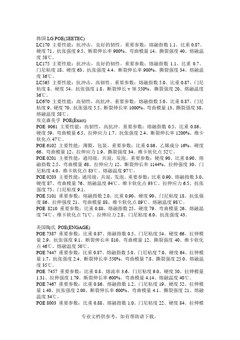
Technical DataBasic technical dataNumber of cylinders.. ... ... ... ... ... ... ... ... ... ... ... ... ... ... ... ... ...6 Cylinder arrangement... ... ... ... ... ... ... ... ... ... ... ...vertical in-line Cycle. ... ... ... ... ... ... ... ... ... ... ... ... ... ... ... ... ... ... ... ... .4 stroke Induction system... ... ... ... turbocharged, air-to-air charge cooling Combustion system.. ... ... ... ... ... ... ... ... ... direct injection diesel Compression ratio. ... ... ... ... ... ... ... ... ... ... ... ... ... ... ... ...16,3:1Bore.. ... ... ... ... ... ... ... ... ... ... ... ... ... ... ... ... ... ... ... ... 130 mm Stroke ... ... ... ... ... ... ... ... ... ... ... ... ... ... ... ... ... ... ... ... 157 mm Cubic capacity .. ... ... ... ... ... ... ... ... ... ... ... ... ... ... ... ..12,5 litres Direction of rotation... ... anticlockwise when viewed from flywheel Firing order (number 1 cylinder furthest from flywheel)1-5-3-6-2-4Estimated total weight of Electropak (dry) ... ... ... ... ... ... .1478 kg Estimated total weight of Electropak (wet) ... ... ... ... ... ... .1582 kgOverall dimensions - Electropak-height... ... ... ... ... ... ... ... ... ... ... ... ... ... ... ... ... ... ... ..1725 mm -length (air cleaner fitted).. ... ... ... ... ... ... ... ... ... ... ... ..2410 mm -width ... ... ... ... ... ... ... ... ... ... ... ... ... ... ... ... ... ... ... . 1120 mmMoments of inertia (mk²)Engine... ... ... ... ... ... ... ... ... ... ... ... ... ... ... ... ... ... ... .1,36 kgm²Flywheel ... ... ... ... ... ... ... ... ... ... ... ... ... ... ... ... ... ... 1.41 kgm²Centre of gravityForward of rear face of cylinder block... ... ... ... ... ... ... ... 650 mm Above crankshaft centre line ... ... ... ... ... ... ... ... ... ... ... 250 mmCyclic irregularity-1500 rev/min ... ... ... ... ... ... ... ... ... ... ... ... ... ... ... ... ... ... ..1,54-1800 rev/min ... ... ... ... ... ... ... ... ... ... ... ... ... ... ... ... ... ... ..1,82PerformanceNote:All data based on operation to ISO 3046-1, BS5514 AND DIN 6271standard reference conditions.All data based on 42584 MJ/kg calorific value for diesel conforming to specification BS2869 ClassA2All ratings certified to within .. ... ... ... ... ... ... ... ... ... ... ... ... + 3%Steady state speed capability at constant load - G2.. ... .. + 0,25%Test conditions-air temperature . ... ... ... ... ... ... ... ... ... ... ... ... ... ... ... ... ...25 °C -barometric pressure.. ... ... ... ... ... ... ... ... ... ... ... ... ... ...100 kPa -relative humidity ... ... ... ... ... ... ... ... ... ... ... ... ... ... ... ... ... 30 %-air inlet restriction at maximum power (nominal).. ... ... ... 2,5 kPa -exhaust back pressure at maximum power (nominal).. ... 6,8 kPa -fuel temperature (inlet pump) ... ... ... ... ... ... ... ... ... ... ... ...40 °CSound levelSound pressure level (exhaust piped away, cooling pack and air cleaner fitted)-1500 rev/min. ... ... ... ... ... ... ... ... ... ... ... ... ... ... ... ... 102 dB(A)-1800 rev/min. ... ... ... ... ... ... ... ... ... ... ... ... ... ... ... .104,6 dB(A)If the engine is to operate in ambient conditions other than those of the test conditions, suitable adjustments must be made for these changes. For full details, contact Perkins Technical Service Department.Emissions capability: All 2206A ratings are to ‘best fuel consumption’ and do not comply to Harmonised International regulation Emission Limits.General installation DesignationUnits Prime Standby Prime Standby 50Hz @ 1500 rev/min60Hz @ 1800 rev/minGross engine powerkWb 324,2368,4373,4406,5Brake mean effective pressure kPa 2061235519842171Combustion air flow (at rated speed)m³/min 21,323,627,429,0Exhaust gas flow (Max.)m³/min 56,664,867,573,5Exhaust gas mass flowkg/min 25,127,832,634,5Exhaust gas temperature (turbocharger outlet)°C630630630660Boost pressure ratio2,83,23,13,4Overall thermal efficiency (nett)%41,340,840,740,3Typical genset electrical output (0.8pf 25 °C)kWe 280320320350kVA 350400400438Assumed alternator efficiency %9292Energy balance Energy in fuelkWt 739,9854,1857,0945,7Energy in power output (gross)kWb 324,2368,4373,4406,5Energy to additional losses kWb 4,95,55,66,1Energy to cooling fan kWm 1419Energy in power output (nett)kWt 305,3348,9348,8381,4Energy to exhaustkWt 213,2245,3244,7273,7Energy to coolant and lubricating oil kWt 113,5128,5130,2139,5Energy to charge cooler kWt 64,879,768,476,5Energy to radiationkWt24,132,240,349,5 - 2206A-E13TAG22200 Series2206A-E13TAG2 2206A-E13TAG3ElectropaKGeneral installationDesignation Units Prime Standby Prime Standby50Hz @ 1500 rev/min60Hz @ 1800 rev/min Gross engine power kWb368,4412,5373,4406,5 Brake mean effective pressure kPa2344263719842171 Combustion air flow (at rated speed)m³/min24,326,427,429,0 Exhaust gas flow (Max.)m³/min64,672,567,573,5 Exhaust gas mass flow kg/min28,130,932,634,5 Exhaust gas temperature (turbocharger outlet)°C630630660660 Boost pressure ratio3,23,53,13,4 Overall thermal efficiency (nett)%41,440,940,740,3Typical genset electrical output (0.8pf 25 °C)kWe320360320350 kVA400450400438Assumed alternator efficiency%9292Energy balanceEnergy in fuel kWt842,6958,2857,0945,7 Energy in power output (gross)kWb368,4412,5373,4406,5 Energy to additional losses kWb5,56,25,66,1 Energy to cooling fan kWm1419Energy in power output (nett)kWt348,9392,3348,8381,4 Energy to exhaust kWt252,6290,4244,7273,7 Energy to coolant and lubricating oil kWt127,3139,9130,2139,5 Energy to charge cooler kWt60,375,568,476,5 Energy to radiation kWt34,039,840,349,6 - 2206A-E13TAG3Rating definitionsPrime powerVariable load. Unlimited hours usage with an average load factor of 70% of the published Prime Power rating over each 24 hour period.A 10% overload is available for 1 hour in every 12 hours of operationStandby powerVariable load. Limited to 500 hours annual usage up to 300 hours of which may be continuous running, No overload is permittedCooling systemRadiatorFace area . ... ... ... ... ... ... ... ... ... ... ... ... ... ... ... ... ... ...1,238 m²Number of rows and materials . ... ... ... ... ... ... .1rows, aluminium Matrix density and material .. ... ... ... ..12 fins per inch, aluminium Width of matrix . ... ... ... ... ... ... ... ... ... ... ... ... ... ... ... . 1048 mm Height of matrix ... ... ... ... ... ... ... ... ... ... ... ... ... ... ... . 1100 mm Weight of radiator (dry). ... ... ... ... ... ... ... ... ... ... ... ... ... ..132 kg Pressure cap setting (min) ... ... ... ... ... ... ... ... ... ... ... ... ..70 kPa Charge coolerFace area.. ... ... ... ... ... ... ... ... ... ... ... ... ... ... ... ... ... ...1,006 m²Number of rows and materials . ... ... ... ... ... ... .1rows, aluminium Matrix density and material .. ... ... ... ..12 fins per inch, aluminium Width of matrix . ... ... ... ... ... ... ... ... ... ... ... ... ... ... ... ... 915 mm Height of matrix ... ... ... ... ... ... ... ... ... ... ... ... ... ... ... . 1100 mm Coolant pumpSpeed @ 1500 rev/min. ... ... ... ... ... ... ... ... ... ... ... 2056 rev/min Speed @ 1800 rev/min. ... ... ... ... ... ... ... ... ... ... ... 2468 rev/min Drive method. ... ... ... ... ... ... ... ... ... ... ... ... ... ... ... ... ... ... .Gear FanDiameter ... ... ... ... ... ... ... ... ... ... ... ... ... ... ... ... ... ... ... 927 mm Drive ratio.. ... ... ... ... ... ... ... ... ... ... ... ... ... ... ... ... ... ... ...0,92:1 Number of blades.. ... ... ... ... ... ... ... ... ... ... ... ... ... ... ... ... ... .. 9 Material. ... ... ... ... ... ... ... ... ... ... ... ... ... ... ... ... ... ... .composite Type.. ... ... ... ... ... ... ... ... ... ... ... ... ... ... ... ... ... ... ... ... . pusher Cooling fan air flow @ 1500 rev/min. ... ... ... ... ... ... ...654 m³/min Cooling fan air flow @ 1800 rev/min. ... ... ... ... ... ... ...788 m³/min CoolantTotal system capacity ... ... ... ... ... ... ... ... ... ... ... ... ... . 51,4 litres Max. top tank temperature ... ... ... ... ... ... ... ... ... ... ... ... ..104 °C Temperature rise across engine... ... ... ... ... ... ... ... ... ... ... 10 °C Max. pressure in engine cooling circuit. ... ... ... ... ... ... ... ..70 kPa Max. permissible external system resistance ... ... ... ... ... ..30 kPa Max. static pressure head on pump.. ... ... ... ... ... ... ... ... ..30 kPa Coolant flow (min) against 30 kPa rstriction@ 1500 rev/min. ... ... ... ... ... ... ... ... ... ... ... ... ... ... .5,3 litres/sec @ 1800 rev/min. ... ... ... ... ... ... ... ... ... ... ... ... ... ... .6,7 litres/sec Thermostat operation range.. ... ... ... ... ... ... ... ... ... ... 87 to 98°C For details of recommended coolant specifications, refer to the Operation and Maintenance Manual for this engine model Duct allowanceDuct allowance 2206A-E13TAG2 - standbyMaximum additional retsriction (duct allowance) to cooling airflow and resultant minimum airflowEngine speedrev/minAmbient clear-ance inhibitedcoolant °CDuctallowancePam³/min 150059200563180059200716Duct allowance 2206A-E13TAG3 - standbyMaximum additional retsriction (duct allowance) to cooling airflow and resultant minimum airflowEngine speedrev/minAmbient clear-ance inhibitedcoolant °CDuctallowancePam³/min 150055200563180059200716Electrical system-type... ... ... ... ... ... ... ... ... ... ... ... ... ... ... .24 Volt negative earth Alternator type ... ... ... ... ... ... ... ... ... ... ... ... ... ... ... ... ... ... .22SI -alternator voltage.. ... ... ... ... ... ... ... ... ... ... ... ... ... ... ... ... ..24V -alternator output ... ... ... ... ... ... ... ... ... ... ... ... ... ... ... ... ... ..70A Starter motor type.. ... ... ... ... ... ... ... ... ... ... ... ... ... ... ... ...39MT -starter motor voltage. ... ... ... ... ... ... ... ... ... ... ... ... ... ... ... ..24V -starter motor power... ... ... ... ... ... ... ... ... ... ... ... ... ... ... .7,8 kW Number of teeth on flywheel.. ... ... ... ... ... ... ... ... ... ... ... ... ..113 Number of teeth on starter pinion.. ... ... ... ... ... ... ... ... ... ... (11)Minimum cranking speed... ... ... ... ... ... ... ... ... ... ... 106 rev/min Starter solenoid maximum-pull-in current @ 0°C ... ... ... ... ... ... ... ... ... ... ... ... ... ... ... 200A -hold-in current @ 0°C... ... ... ... ... ... ... ... ... ... ... ... ... ... ... ..25A Cold start recommendations-5°C to -10°Coil... ... ... ... ... ... ... ... ... ... ... ... ... ... ... ... ... ..SAE grade 15W40 Starter ... ... ... ... ... ... ... ... ... ... ... ... ... ... ... ... ... ... ... ... ...42MT Battery ... ... ... ... ... ... ... ... ... ... ... ... ... ... ... ... ... ... ... ... 24 volts Max. breakaway current. ... ... ... ... ... ... ... ... ... ... ... ..1311 amps Cranking current ... ... ... ... ... ... ... ... ... ... ... ... ... ... ... 588 amps Starting aids (ECM controlled)... ... ... ... ... ... ... ... ... ... ... ... none Min. mean cranking speed. ... ... ... ... ... ... ... ... ... ... .106 rev/min -11°C to -25°Coil... ... ... ... ... ... ... ... ... ... ... ... ... ... ... ... ... ... SAE grade 5W40 Starter ... ... ... ... ... ... ... ... ... ... ... ... ... ... ... ... ... ... ... ... ...42MT Battery ... ... ... ... ... ... ... ... ... ... ... ... ... ... ... ... ... ... ... ... 24 volts Max. breakaway current. ... ... ... ... ... ... ... ... ... ... ... ..1585 amps Cranking current ... ... ... ... ... ... ... ... ... ... ... ... ... ... ... 828 amps Starting aids (ECM controlled)... block heater 1,5kW (110V/240V) Min. mean cranking speed. ... ... ... ... ... ... ... ... ... ... .106 rev/min Notes:z Battery capacity is defined by the 20 hour ratez The oil specification should be for the minimum ambient temperature as the oil will not be warmed by the immersion heaterz Breakaway current is dependent on the battery capacity available. Cables should capable of handling transient current twice that of cranking current.Exhaust systemMaximum back pressure-1800 rev/min . ... ... ... ... ... ... ... ... ... ... ... ... ... ... ... ... .10,0 kPa Exhaust outlet, internal diameter. ... ... ... ... ... ... ... ... ... . 123 mm Fuel systemInjection system... ... ... ... ... ... ... ... ... ... ... ... ... ... ... ... ... ..MEUI Injector type. ... ... ... ... ... ... ... ... ... ... ... ... ... ... ... ... ... ... ..MEUI Governor type.. ... ... ... ... ... ... ... ... ... ... ... ... ... ... ... ... electronic Governing conforms to ... ... ... ... ... ... ... ... .ISO 8528-5 Class G2 Injector pressure.. ... ... ... ... ... ... ... ... ... ... ... ... ... ... ... .207 MPa Fuel lift pump-lift pump type.. ... ... ... ... ... ... ... ... ... ... ... ... ... ... ... .gear driven -lift pump delivery @1500 rev/min... ... ... ... ... ... ... 480 litres/hour -lift pump delivery @1800 rev/min... ... ... ... ... ... ... 600 litres/hour -lift pump delivery pressure. ... ... ... ... ... ... ... ... ... ... ... ..621 kPa -max. suction head at pump inlet ... ... ... ... ... ... ... ... ... ... ... .3 m -max. static pressure head.. ... ... ... ... ... ... ... ... ... ... ... ... ... .4 m -max. fuel inlet temperature. ... ... ... ... ... ... ... ... ... ... ... ... ..55 °C -fuel filter spacing primary... ... ... ... ... ... ... ... ... ... ... .10 microns -fuel filter spacing secondary... ... ... ... ... ... ... ... ... ... ...2 microns Fuel specificationBS2869 Class A2 or BSEN590ASTM D975 Class 1D and class 2DNote:For further information on fuel specifications and restrictions, refer to the OMM, “Fluid Recommendations” for this engine model. Induction systemMaximum air intake restriction-clean filter... ... ... ... ... ... ... ... ... ... ... ... ... ... ... ... ... ... ...2,5 kPa -dirty filter. ... ... ... ... ... ... ... ... ... ... ... ... ... ... ... ... ... ... ...6,4 kPa -air filter type ... ... ... ... ... ... ... . paper element - 15 inch diameterLubrication systemMaximum total system oil capacity ... ... ... ... ... ... ... ... ... .40 litres Minimum oil capacity in sump... ... ... ... ... ... ... ... ... ... ..32,5 litres Maximum oil capacity in sump.. ... ... ... ... ... ... ... ... ... ... .38 litres Maximum engine operating angles -front up, front down, right side, left side ... ... ... ... ... ... ... ... ... 7 °Lubricating oil-oil flow @ 1500 rev/min... ... ... ... ... ... ... ... ... ... ... 140 litres/min -oil flow @ 1800 rev/min... ... ... ... ... ... ... ... ... ... ... 172 litres/min -oil pressure at bearings @ 1500 rev/min. ... ... ... ... ... ... 310 kPa -oil pressure at bearings @ 1800 rev/min. ... ... ... ... ... ... 358 kPa -oil pressure at bearings (min).. ... ... ... ... ... ... ... ... ... ... 270 kPa -oil temperature (continuous operation) ... ... ... ... ... ... ... ..113 °C -oil consumption at full load as a % of fuel consumption.. ...0.15% Oil filter screen spacing. ... ... ... ... ... ... ... ... ... ... ... ... 30 microns Oil consumption as % of fuel consumption... ... ... ... ... ... ... ... 0,1 Sump drain plug tapping... ... ... ... ... ... ... ... ... ... ... ... .1 1/8 UNF Lubricating oil specification... ... ... ... ... ... API-CH4 - SAE15W-40 Recommended SAE viscosityEngine Oil ViscosityEMA LRG-1API CH-4 Viscosity GradeAmbient Temperature Minimum MaximumSAE 0W20-40 °C10 °CSAE 0W30-40 °C30 °CSAE 0W40-40 °C40 °CSAE 5W30-30 °C30 °CSAE 5W40-30 °C40 °CSAE 10W30-20 °C40 °CSAE 15W40-10 °C50 °C MountingsMaximum static bending moment at rear face of block. ...1356 Nm Fuel consumption2206A-E13TAG2 - 1500 rev/minLoad g/kWhr l/hr Standby19580 110% Prime power19577 100% Prime power19671 75% of Prime power19854 50% of Prime power203372206A-E13TAG3 - 1500 rev/minLoad g/kWhr l/hr Standby19490 110% Prime power19689 100% Prime power19781 75% of Prime power19962 50% of Prime power202422206A-E13TAG2 - 1800 rev/minLoad g/kWhr l/hr Standby19387 110% Prime power19588 100% Prime power19681 75% of Prime power19962 50% of Prime power205432206A-E13TAG3 - 1800 rev/minLoad g/kWhr l/hr Standby19387 110% Prime power19588 100% Prime power19681 75% of Prime power19962 50% of Prime power20543All fuel consumption figures are based on Nett powerAll information in the document is substantially correct at the time of printing but may be subsequently altered by the company.Distributed by2200 Series2206A-E13TAG22206A-E13TAG3Load acceptance TAG2 (cold) Initial load application: When engine reaches rated speed(15 seconds maximum after engine starts to crank)DescriptorUnits 50 Hz 60Hz % of prime power %6680Load (nett)kWm 184,8256Transient frequency deviation%<10<10Frequency recoverySeconds55Second load application: When engine reaches rated speed(5 seconds after initial load application)DescriptorUnits 50 Hz 60Hz % of prime power %7385Load (nett)kWm 204,4272Transient frequency deviation%<10<10Frequency recoverySeconds55TAG3 (cold) Initial load application: When engine reaches rated speed(15 seconds maximum after engine starts to crank)DescriptorUnits 50 Hz 60Hz % of prime power %5880Load (nett)kWm 185,6256Transient frequency deviation%<10<10Frequency recoverySeconds55Second load application: When engine reaches rated speed(5 seconds after initial load application)DescriptorUnits 50 Hz 60Hz % of prime power %6585Load (nett)kWm 208272Transient frequency deviation%<10<10Frequency recoverySeconds55The information shown above complies with the requirements of classification 3 and 4 of ISO 8528-12 and G2 operating limits stated in ISO 8528-5The above figures were obtained under the following test conditions:-minimum engine block temperature.. ... ... ... ... ... ... ... ... ... ... ... ... ... ... ... ... ... ... ... ... ... ... ... ... ... ... ... ... ... ... ... ... ... ... ... ... . 45 °C -ambient temperature. ... ... ... ... ... ... ... ... ... ... ... ... ... ... ... ... ... ... ... ... ... ... ... ... ... ... ... ... ... ... ... ... ... ... ... ... ... ... ... ... ... ... ..15 °C -governing mode ... ... ... ... ... ... ... ... ... ... ... ... ... ... ... ... ... ... ... ... ... ... ... ... ... ... ... ... ... ... ... ... ... ... ... ... ... ... ... ... ... ... isochronous -alternator efficiency... ... ... ... ... ... ... ... ... ... ... ... ... ... ... ... ... ... ... ... ... ... ... ... ... ... ... ... ... ... ... ... ... ... ... ... ... ... ... ... ... ... ... ... 92%-alternator inertia ... ... ... ... ... ... ... ... ... ... ... ... ... ... ... ... ... ... ... ... ... ... ... ... ... ... ... ... ... ... ... ... ... ... ... ... ... ... ... ... ... ... ... 6,9 kgm²-under frequency roll off (UFRO) point set to. ... ... ... ... ... ... ... ... ... ... ... ... ... ... ... ... ... ... ... ... ... ... ... ... ... ... ... ... ... 1 Hz below rated -UFRO rate set to... ... ... ... ... ... ... ... ... ... ... ... ... ... ... ... ... ... ... ... ... ... ... ... ... ... ... ... ... ... ... ... ... ... ... ... 2% voltage / 1% frequency LAM on/off.. ... ... ... ... ... ... ... ... ... ... ... ... ... ... ... ... ... ... ... ... ... ... ... ... ... ... ... ... ... ... ... ... ... ... ... ... ... ... ... ... ... ... ... ... ... ... ... ...off All tests were conducted using an engine which was installed and serviced to Perkins Engines Company Limited recommendations.Note:The general arrangement drawings shown in this data sheet are for guidance only. For installation purposes, latest versions should be requested from the Applications Dept., Perkins Engines Stafford, ST16 3UB United Kingdom.P u b l i c a t i o n N o . T P D 1687E 2. O c t o b e r 2008 P e r k i n s E n g i n e s C o m p a n y L i m i t e dPerkins Engines Company LimitedPeterborough PE1 5NA United Kingdom Telephone +44 (0) 1733 583000Fax +44 (0) 1733 。
Arista C-230 Wi-Fi 6 AP 产品说明书
Data Sheet AccessC-230 provides Wi-Fi networks that require less time and resources to deploy and maintain compared to traditional devices, resulting in significant cost savings.•Plug and play provisioning using either Cloud or On-premise deployments - Arista Access Points take less than two minutes to activate and configure after connecting to the cloud•Support for up to eight individual SSIDs per radio providing maximum flexibility in network design•Network controls like NAT, Firewall and QoS implemented at the Access Point, ensuring faster and more reliable networks •Continuous scanning of all 2.4 GHz and 5 GHz channels by a dedicated 2x2 third radio provides a dynamic, 360-degree view of the RF environment to assist in RF optimization and client handling•Network availability and performance assurance using the third radio as a client to conduct on-demand and scheduled connectivity and performance tests•Smart steering addresses sticky client issues by automatically pushing clients with low data rates to a better access point•Band steering manages channel occupancy, pushing clients to the 5 GHz channel for optimal throughput•Smart load balancing distributes load evenly across neighbouring APs to optimize the use of network resources•Arista Wi-Fi’s distributed data plane architecture continues to serve users and secure the network even if connection with the management plane is interrupted•Interference avoidance from LTE/3G small/macro cells in commonly used TDD/FDD frequency bandsSecurityC-230 offers complete visibility and control of the wireless airspace ensuring network integrity while actively protecting users without manual intervention.•C-230 is equipped with industry leading fully integrated wireless intrusion prevention capabilities•Multifunction third radio provides uninterrupted spectrum scanning or client emulation for always on security coverage alongside dedicated 2.4G/5G client radios.•Arista’s patented Marker Packets TM help accurately detect rogue access points on any network while minimizing false positives•Third radio used as a dedicated security sensor for 24x7x365 scanning and automated over-the-air (OTA) prevention•Deterministic rogue AP detection and prevention by monitoring all WiFi and non-WiFi VLANs.•Over-the-air and on-the-wire prevention techniques assure automatic and reliable threat prevention to keep unauthorized clients and rogue APs off the network without impacting authorized connections.•Access Points autonomously scan for wireless threats and enforce security policy even if disconnected from the cloud management plane•VLAN monitoring enables a virtual connection to non-WiFi networks for complete network rogue detection and preventionAnalyticsThe C-230 collects telemetry on connected and unconnected WiFi clients and supports immersive guest network experiences that help Arista’s customers develop and reinforce the relationship with their end customers.•Reports of customer footfall, demographic, loyalty and other analytics provide insightful and actionable information.•Supports proximity marketing programs that trigger when certain devices are present, which includes automatic messaging vis MMSin-browser notifications and real time notifications sent to 3rd party systems that alert to the presence of enrolled devices.Data SheetWiFi SpecificationsIEEE 802.11a/n/ac/axFrequency BandScanning TransmissionAll regions USA & Canada (FCC/IC)Europe (ETSI) 5GHz Band4.92 ~5.08 GHz5.15 ~ 5.25 GHz 5.25 ~ 5.35 GHz 5.47~ 5.725 GHz 5.725~ 5.825 GHz5.15 ~ 5.25 GHz 5.25 ~ 5.35 GHz 5.725~ 5.825 GHz5.15 ~ 5.25 GHz 5.25 ~ 5.35 GHz 5.47~ 5.725 GHzDynamic Frequency Selection DFS and DFS2 Modulation Type OFDM / OFDMA Peak Data Rates Up to 2.4 GbpsAntennaIntegrated modular high efficiency PIFA antenna x4 (peak gain: 3.9 dBi)Operational Specifications Input Power12V DC (5.5mm overall diameter/2.1mm center pin hole) PoE+ power•••Full function U SB off Max EIRP 1 of 31.5 dBm at 5GHz, 28 dBm at 2.4GHz 5 GHz limited to 2x2 operation2 access radios; one 2x2:2 2.4GHz and one 4x4:4 5GHz radio for simultaneous dual band access.1 multi-function 2x2 radio for continuous WIPS and client connectivity tests Number of RadiosMU-MIMO4X4 on 5GHz radio and 2X2 on 2.4GHz radioNumber of Spatial Streams 4 for 5GHz radios, 2 for 2.4GHz radio, 2 for multipurpose radio Maximum EIRP35dBm on 5GHz radio (max) and 31dBm on 2.4GHz radio (max)1; 80+80MHz Non-Contiguous Channel Bonding No Bandwidth AgilityYes3G/4G Macro and Small Cells InterferenceMitigation YesFrequency Bands 22.4-2.4835 GHz, 4.9-5.0GHz, 5.15-5.25 GHz; (UNII-1), 5.25-5.35 GHz, 5.47-5.6 GHz, 5.650-5.725 GHz (UNII-2), 5.725-5.85 GHz (UNII-3)Dynamic Frequency SelectionSupported in compliance to all latest amendments from FCC, CE, IC, TELEC, KCC, NCC and ANZ regarding certifications.Max Clients Supported 1024 (512 clients per radio) (dependent upon use cases)1 Max EIRP will be restricted to Country/Regulatory domain limits 2The frequency ranges are restricted to Country/Regulatory domain limits•PoEData SheetIEEE802.11b/g/n/axFrequency BandScanning TransmissionAll regions USA & Canada (FCC/IC) Europe (ETSI)2.4GHz Band2400 ~ 2483.5 MHz 2400 ~ 2473.5 MHz 2400 ~ 2483.5 MHz Modulation Type DSSS / OFDM / OFDMAPeak Data Rates Up to 0.6 GbpsAntenna Integrated modular high efficiency PIFA antenna x2 (peak gain: 3 dBi)Receive Sensitivity5GHz 2.4GHzMode Rate Sensitivit y (dBm)802.11a 6 Mbps-93 54 Mbps-7611n_HT20MCS 0-94 MCS 7-7611n_HT40MCS 0-91 MCS 7-7311ac_VHT20MCS 0-94 MCS 8-7211ac_VHT40MCS 0-91 MCS 9-6811ac_VHT80MCS 0-88 MCS 9-6511ax_HE20MCS 0-94 MCS 11-6511ax_HE40MCS 0-91 MCS 11-6211ax_HE80MCS 0-88MCS 11-59Mode Rate Sensitivit y (dBm)802.11b1 Mbps-9811 Mbps-90802.11g6 Mbps-9354 Mbps-7711n_HT20MCS 0-94MCS 7-7611n_HT40MCS 0-91MCS 7-7311ax_HE20MCS 0-94MCS 11-6511ax_HE40MCS 0-91MCS 11-62Data Sheet Maximum EIRP5GHz 2.4GHzMode Rate Power(dBm)802.11a6 ~ 18 Mbps 35 24 ~ 54 Mbps 35802.11n_HT20 MCS 0 ~ 4 35 MCS 5 ~ 7 35802.11n_HT40 MCS 0 ~ 4 35 MCS 5 ~ 7 35802.11ac_VHT20 MCS 0 ~ 4 35 MCS 5 ~ 7 35 MCS 8 ~ 9 35802.11ac_VHT40 MCS 0 ~ 4 35 MCS 5 ~ 7 35 MCS 8 ~ 9 34802.11ac_VHT80 MCS 0 ~ 4 35 MCS 5 ~ 7 35 MCS 8 ~ 9 34802.11ax_HE20MCS 0 ~ 4 35 MCS 5 ~ 7 35 MCS 8 ~ 9 35 MCS 10- 11 34802.11ax_HE40MCS 0 ~ 4 35 MCS 5 ~ 7 35 MCS 8 ~ 9 34 MCS 10- 11 34802.11ax_HE80MCS 0 ~ 4 35MCS 5 ~ 7 34MCS 8 ~ 9 34MCS 10 ~ 11 34Mode!Rate!Power(dBm)!802.11b 1 ~ 11 Mbps 31802.11g6 ~ 18 Mbps 3124 ~ 54 Mbps 31802.11n_HT20MCS 0 ~ 4 31MCS 5 ~ 7 31802.11n_HT40MCS 0 ~ 4 31MCS 5 ~ 7 31802.11ax_HE20MCS 0 ~ 4 31MCS 5 ~ 7 29MCS 8 ~ 9 29MCS 10 ~ 11 29802.11ax_HE40MCS 0 ~ 4 31MCS 5 ~ 7 29MCS 8 ~ 9 28MCS 10 ~ 11 28Pe ak Gain:3.9dBiData SheetRegulatory Specifications RF a nd ElectromagneticCountry CertificationUSA FCC Part 15.247, 15.407 Canada ICEuropeCE EN300.328, EN301.893, EN301 489-1, EN55032, EN62311Countries covered under Europe certification: Austria, Belgium, Bulgaria, Croatia, Cyprus, Czechia, Denmark, Estonia, Finland, France, Germany, Greece, Hungary, Ireland, Italy,Latvia, Lithuania, Luxembourg, Malta, the Netherlands, Poland, Portugal, Romania, Slovakia, Slovenia, Spain, Sweden, United Kingdom.*For complete country certification records, please visit the site: https:///en/support/product-certificateSafetyCountryCertificationUSA UL 60950 UL 2043 CanadacUL 60950European Union (EU) EN 60950, EN 62368-1 TaiwanCNS14336-1Ordering Information Access PointPart NumberDescriptionAP-C230 C-230 4x4 tri radio 802.11ax (WiFi 6) access point with internal antennas AP-C230-SS-5Y C-230 AP with 5 years bundled Cognitive Cloud SW subs cription AP-C230-SS-3Y C-230 AP with 3 years bundled Cognitive Cloud SW subscriptionPart NumberDescriptionPWR-AP-W4 Universal AC power supply for C-230, 12VDC, 3.3AHeadquartersSupportSales5453 Great America Parkway SantaClara, California 95054408-547-5500support-wifi@408-547-5502866-476-0000sales@ 408-547-5501 866-497-0000Copyright 2023 Arista Networks, Inc. The information contained herein is subject to change without notice. Arista, the Arista logo and EOS are trademarks of Arista Networks. Other product or service names may be trademarks or service marks of others.October 26, 2023Mounting OptionsFor details of mounting options, see the Access Points Mounting Brackets Guide P owerPWR-AP-PLUS-NAOne port PoE+ injector for use with all Access Point models. Includes USA power cord. Not for outdoor use.。
伟肯变频器用户手册
伟肯变频器用户手册安装和运行前,请务必遵照如下的起动和运行快速指南操作,并依次完成其中11个操作步骤。
如有任何问题,请与当地经销商联系。
快速指南1. 检查产品是否与定单相符,见第3章。
2. 进行任何调试前,请仔细阅读第1章中的安全规程。
3. 进行机械安装前,请根据第5章的说明检查外部环境条件和变频器周边的最小间距。
4. 按第6章的说明检查电机电缆、主电源电缆、主电源熔断器的规格和电缆的连接情况。
5. 根据第5章中的安装说明进行安装。
6. 根据§6.1.1中的说明检查控制电缆规格及接地系统。
7. 根据第7章中的说明使用控制面板。
8. 所有的参数都有工厂设定的缺省值。
为了确保正确运行,请检查下列电机铭牌数据和参数组P2.1中相应的参数设置。
见§8.3.2。
• 电机额定电压P2.1.6• 电机额定频率P2.1.7• 电机额定转速P2.1.8• 电机额定电流P2.1.9• 电机功率因数P2.1.10所有的参数说明见多目标控制应用手册。
9. 阅读第8章,按照调试步骤进行操作。
10. 至此,可以开始使用Vacon NXL变频器了。
11. 在本手册的结尾,您会看到有关默认I/O,控制面板菜单,监控值,故障代码和基本参数的快速帮助。
违反上述操作步骤所造成的任何损失,Vacon Plc概不负责。
目录VACON NXL用户手册目录1 安全指导2 EU认证3 收货4 技术数据5 安装6 电缆和接线7 控制面板8 调试9 故障跟踪10 选件卡OPT-AA的描述11 选件卡OPT-AI的描述VACON NXL多目标控制应用手册vacon • 3Vacon China电话: +86-10-51280006 传真: +86-10-65813733 24小时支持热线: +86-137******** Email :***************.cn关于VACON NXL 用户手册和多目标控制应用手册恭喜您选择了Vacon NXL 变频器所提供的平滑控制!用户手册将为您提供有关Vacon NXL 变频器的安装,调试和操作的必要信息。
Lexmark XC2130 7527 496 用户手册说明书
XC2130用戶手冊2017 年 11 月機器型式:7527機種:496內容安全資訊 (7)瞭解印表機 (9)尋找印表機相關資訊 (9)選取印表機放置地點 (10)印表機配置 (11)瞭解掃描器的基本功能 (12)使用自動送件器和掃描器玻璃面板 (12)瞭解印表機控制面板 (13)使用印表機控制面板 (13)瞭解主畫面 (13)瞭解「睡眠」按鈕和指示燈的顏色 (15)使用觸控式螢幕按鈕 (15)設定及使用主畫面應用程式 (17)尋找電腦的 IP 位址 (17)尋找印表機的 IP 位址 (17)存取 Embedded Web Server(內嵌式 Web 伺服器) (17)自訂主畫面 (18)瞭解不同的應用程式 (18)啟動主畫面應用程式 (19)設定「遠端操作面板」 (22)匯出及匯入配置 (23)其他印表機設定 (24)安裝內接式選購品 (24)安裝硬體選購品 (30)連接電纜 (33)設定印表機軟體 (34)網路功能 (35)驗證印表機設定 (38)載入紙張和特殊材質 (39)設定紙張尺寸和類型 (39)配置 Universal(通用尺寸)紙張設定 (39)載入 250 張和 550 張紙匣組件 (39)載入手動輔助式送紙器 (42)載入 650 張雙層紙匣組件 (43)將材質載入多用途送紙器 (44)連結及解除連結紙匣組件 (46)紙張和特殊材質指南 (49)使用特殊材質 (49)紙張指引 (52)支援的紙張尺寸、類型和重量 (55)列印 (58)列印表單 (58)列印文件 (58)從快閃儲存碟列印 (60)從行動裝置列印 (62)列印機密工作和其他保留工作 (63)列印資訊頁 (64)取消列印工作 (65)複印 (66)進行複印 (66)複印相片 (67)複印在特殊材質上 (67)利用印表機控制面板建立複印快捷鍵 (68)自訂複印設定 (69)在複印文件上放置資訊 (73)取消複印工作 (74)瞭解複印選項 (75)以電子郵件寄送 (79)設定印表機電子郵件功能 (79)建立電子郵件快捷鍵 (79)以電子郵件寄送文件 (80)自訂電子郵件設定 (82)取消電子郵件 (82)瞭解電子郵件選項 (83)傳真 (86)設定印表機傳真功能 (86)傳送傳真 (101)建立快捷鍵 (104)自訂傳真設定 (104)取消外送的傳真 (106)保留與轉發傳真 (106)瞭解傳真選項 (107)掃描 (110)使用 Scan to Network(掃描至網路) (110)掃描至 FTP 位址 (110)掃描至電腦或快閃儲存碟 (112)瞭解掃描選項 (114)瞭解印表機功能表 (117)功能表清單 (117)耗材功能表 (118)紙張功能表 (118)報告功能表 (126)網路/連接埠 (128)安全性功能表 (136)設定功能表 (140)節省金錢並注重環保 (186)節省紙張和碳粉 (186)省電 (186)回收利用 (190)固定印表機 (191)使用安全鎖功能 (191)揮發性聲明 (191)清除揮發性記憶體 (192)清除非揮發性記憶體 (192)清除印表機硬碟記憶體 (193)配置印表機硬碟加密 (193)尋找印表機安全資訊 (194)維護印表機 (195)存放耗材 (195)清潔印表機 (195)檢查零件及耗材狀態 (197)預估剩餘頁數 (197)訂購耗材 (197)更換耗材 (200)移動印表機 (219)管理印表機 (220)尋找進階網路功能及管理者資訊 (220)檢查虛擬顯示幕 (220)設定電子郵件警示 (220)檢視報告 (220)從 Embedded Web Server(內嵌式 Web 伺服器)配置耗材通知 (221)修改機密列印設定 (221)複製印表機設定至其他印表機 (222)回復出廠預設值 (222)清除夾紙 (224)避免夾紙 (224)識別夾紙位置 (225)標準出紙槽中發生夾紙 (226)前門中發生夾紙 (227)紙匣組件中的夾紙 (229)紙張夾在手動輔助式送紙器中 (230)多用途送紙器中的夾紙 (231)自動送稿器中發生夾紙 (232)疑難排解 (233)瞭解印表機訊息 (233)解決印表機問題 (248)解決列印問題 (253)解決複印問題 (278)解決傳真問題 (281)解決掃描器問題 (286)解決主畫面應用程式問題 (290)Embedded Web Server(內嵌式 Web 伺服器)未開啟 (291)聯絡客戶支援中心 (292)注意事項 (293)產品資訊 (293)版本注意事項 (293)耗電量 (299)索引 (302)安全資訊請將電源線連接到本產品附近具有適當等級且妥善接地的電源插座,而且必須易於使用。
PTX-LCD系列激励器说明书

3
音频输入 音频母板 立体声/ 单声道板 PLL/VCO
CPU 板板
功放
图 4-2 激励器俯视图
1.4 激励器原理框图
激励器连线框图如图 4-3 所示:
音频接口板
编码板或 单声/MPX板
音频输入板 音频母板
电源板板 变压器 开关电源
散热器 显示面板卡
VCO板 PLL板
(3) 选件清单如表 4-3 所示。(机器的标准配置不包括选件,如用户需要请
另行购置。)
/03 /08 /AUDIOINP-DIG
表 4-3 24V外电源SP 技术的数/模音频接口,集成数字 立体声编码器及 RDS 编码器
(4) 数字音频输入接口(AUDIOINP-DIG)指标如表 4-4 所示。
PTX-LCD激励器严格按照模块化方法设计:不同功能由不同模块完成,各模 块直接相接(某一模块的凸性接口与另一模块的凹性接口接插)或由连接器终端 电缆相连。这种设计理念使得单一模块的维修和替换变得非常简单。
1.2 激励器外观图
激励器外观图如图 4-1 所示。
图 4-1 激励器外观图
1.3 激励器内部布局
(5) 基于 DSP 技术的数/模音频接口(TRDSP)指标如表 4-5 所示。
模拟音频输入 A/D 转换 连接器 阻抗 输入电平 最大输入电平 数字音频输入 连接器 数据格式 采样率 数字音频输出 连接器 数据格式 采样率 MPX 输出 D/A 转换 导频频率 导频电平 导频相位 38kHz 副载波抑制度 MPX 输出电平 立体声分离度 MPX 输出噪声 预加重 预加重线性度 15kHz 低通滤波器频响 19kHz 处衰减 限幅斩波 AGC
>82dB(RMS,50us 预加重,75kHz 频偏) ±0.05dB (20kHz ~ 53kHz) ±0.2dB (53kHz ~ 100kHz) <0.02% <0.02% (1K+1.3K,1:1,75kHz 频偏) >50dB(典型值 60dB)
Fusor 130 剧涨塑料(超级快速)技术数据表说明书
Fusor® 130 Rigid Foam (Super Fast)Technical Data SheetFusor® 130 rigid foam is a two-component, urethane-based foam used for sound & vibration dampening, reinforcement, and sealing/filling of fender rails, pillars, rocker panels, quarter panels and floors.Features and Benefits:Versatile – expands to ten times its size.Excellent Appearance – matches OEM hard foam appearance.Durable – provides tough compressive strength for maximum energy absorption.NVH Reduction – reduces noise, vibration and harshness for a quieter ride.Environmentally Resistant – does not retain moisture. Easy to Use – super fast application; provides full foam expansion in 4 minutes.Application:Prepare – Remove any necessary panels and use a drop cloth to protect the surrounding area against accidental drippage.Apply – Load cartridge into a manual applicator and remove the end caps from cartridge packaging.Note: Due to the thin viscosity of the material, a pneumatic applicator is not recommended.Prepare foam for application by gently squeezing out a small amount of material to ensure that foam freely flows from both sides of the cartridge. Attach mixing tip.Apply a bead of foam between the vibrating panels or dispense a stream of material to fill a void. Avoid dispensing material too quickly. Foam will expand approximately 10 times its original volume to fill voids or eliminate vibration. When filling voids, build a dam to locate the foam where desired. When sealing pillars or posts, apply a sufficient amount of foam; approximately 1/3 to 1/2 of a cartridge may be needed depending on size and configuration of void. Remove the mixing tip immediately after usage and install supplied cartridge plugs to avoid pressure build-up.Note: Various applications, cleaners/solvents and coatings may not be compatible with this product and should be tested by the user before proceeding with intended repair procedure.Finish – If desired, foam can be painted in 10 minutes.For more application information, refer to / fusor for standard operating procedures or application training videos.Technical Tips• When applying Fusor 130 rigid foam to a vertical panel, dispense the material to the end of the tip. Allow the material to start foaming, then slowly dispense into the appropriate area. This will keep the material from runningdown the panel.Parker LORDEngineered Materials Group 111 LORD DriveCary, NC 27511-7923USAphone +1 877 ASK LORD (275 5673)Instructions contained in this document need to be followed to qualify for the LORD Fusor Lifetime Guarantee. Values stated in this technical data sheet represent typical values as not all tests are run on each lot of material produced. For formalized product specifications for specific product end uses, contact the Customer Support Center.Information provided herein is based upon tests believed to be reliable. In as much as Parker LORD has no control over the manner in which others may use this information, it does not guarantee the results to be obtained. In addition, Parker LORD does not guarantee the performance of the product or the results obtained from the use of the product or this information where the product has been repackaged by any third party, including but not limited to any product end-user. Nor does the company make any express or implied warranty of merchantability or fitness for a particular purpose concerning the effects or results of such use.WARNING — USER RESPONSIBILITY . FAILURE OR IMPROPER SELECTION OR IMPROPER USE OF THE PRODUCTS DESCRIBED HEREIN OR RELATED ITEMS CAN CAUSE DEATH, PERSONAL INJURY AND PROPERTY DAMAGE.This document and other information from Parker-Hannifin Corporation, its subsidiaries and authorized distributors provide product or system options for further investigation by users having technical expertise.The user, through its own analysis and testing, is solely responsible for making the final selection of the system and components and assuring that all performance, endurance, maintenance, safety and warning requirements of the application are met. The user must analyze all aspects of the application, follow applicable industry standards, and follow the information concerning the product in the current product catalog and in any other materials provided from Parker or its subsidiaries or authorized distributors.To the extent that Parker or its subsidiaries or authorized distributors provide component or system options based upon data or specifications provided by the user, the user is responsible for determining that such data and specifications are suitable and sufficient for all applications and reasonably foreseeable uses of the components or systems.©2021 Parker Hannifin - All Rights ReservedInformation and specifications subject to change without notice and without liability therefor. Trademarks used herein are the property of their respective owners.Fusor 130 Foam — Technical Data SheetOD DS6220 01/21 Rev.1Shelf Life/StorageShelf life is 24 months from date of manufacture when stored at 75°F (24°C) in original, unopened container.Cautionary Information:Before using this or any Parker LORD product, refer to the Safety Data Sheet (SDS) and label for safe use and handling instructions.For industrial/commercial use only. Must be applied by trained personnel only. Not to be used in household applications. Not for consumer use.Fusor ® Repair Products Lifetime Guarantee*LORD Assembly & Protection Solutions Division of Parker-Hannifin Corporation (“Parker LORD”) guarantees to the user that Fusor ® Repair Products (adhesives, primers, seam sealers and foams only), when used in strict accordance with Parker LORD application and use instructions, will provide a durable repair for the life of the vehicle per the product’s technical data sheet. The user is solely responsible for determining the Fusor product and application method for the repair. Application and product guidance can be found on .THIS EXPRESS WARRANTY IS MADE IN LIEU OF AND EXCLUDES ANY AND ALL OTHER WARRANTIES, EXPRESS OR IMPLIED, BY OPERATION OF LAW OR OTHERWISE, INCLUDING THE IMPLIED WARRANTIES OF MERCHANTABILITY AND FITNESS FOR A PARTICULAR PURPOSE.Parker LORD shall not be liable under any circumstance for any liability, loss, damage or expense directly or indirectly arising from the application and use of Fusor Products sold hereunder or from any other cause. Parker LORD shall not be liable under any circumstances for consequential, indirect or special damages. PARKER LORD’S LIABILITY FOR BREACH OF WARRANTY HEREUNDER IS IN ALL INSTANCES LIMITED SOLELY AND EXCLUSIVELY TO THE REASONABLE COSTS OF REPAIR AND/OR REPLACEMENT OF THE BONDED COMPONENTS OF THE VEHICLE.This guarantee shall only apply to the above referenced Fusor products sold by Parker LORD on or after January 1, 2001.Fusor Metal Bonding Adhesives shall only be used for the adhesive-only bonding (no welds or rivets) of metal to metal assemblies (steel or aluminum) in full or partial panel replacements of door skins, roof skins, quarter panels, rear body panels and other outer body sheet metal where approved by the vehicle manufacturer.Fusor products shall not be used for adhesive-only bonding of any structuralcomponent unless specifically recommended by the vehicle manufacturer. Structural panels must be replaced in strict compliance with vehicle manufacturer guidelines. If in doubt as to what is a structural component or the proper installation method, contact the vehicle manufacturer. Further, any Fusor products used in marine composite repair, such as with personal water craft and the like, shall be limited to repairs above the water line.If you have any questions or need to receive proper use instructions, contact the Parker LORD Customer Support Center at +1 800 234 Fusor (3876) or visit .To comply with the requirements of the Fusor Repair Products Lifetime Guarantee, attach a copy of this completed page to the repair record, and retain with your files:Vehicle Make/Model: _____________________________________________________Vehicle Identification Number: _____________________________________________Fusor Product(s) Used for Repair: __________________________________________Lot Number(s) on Cartridge(s) Used for Repair: _____________________________*This guarantee is void if product is used after the date printed on the cartridge label.Parker LORD Terms and Conditions of Sale shall apply to all sales of Fusor products.。
Philips XITANIUM LED 120A0700C28说明书
Remarks
Revised 05/16/2012
PHILIPS LIGHTING ELECTRONICS N.A.
10275 WEST HIGGINS ROAD · ROSEMONT, IL 60018 Tel: 800-322-2086 · Fax: 888-423-1882 · /advance Customer Support/Technical Service: 800-372-3331 · OEM Support: 866-915-5886
LED120A0700C28FO
Brand Name Driver Type Input Voltage Input Frequency
RoHS Approbations
Status
XITANIUM Electronic 120 50/60Hz Yes UL, CSA Active
Approval
N.T. N.T. N.T.
LED120A0700C28FO
Brand Name Driver Type Input Voltage Input Frequency
RoHS Approbations
Status
XITANIUM Electronic 120 50/60Hz Yes UL, CSA Active
Installation & Application Notes:
Section I – Physical Characteristics 1.1 LED Driver shall be installed inside an electrical enclosure. 1.2 Wiring inside electrical enclosure shall comply with 600V/105°C rating or higher.
APC Back-UPS Pro 1500VA 865W 230V 10x IEC C13 出口 可
Product datasheetSpecificationsAPC Back-UPS Pro, 1500VA/865W,Tower, 230V, 10x IEC C13 outlets,AVR, LCD, User Replaceable BatteryBR1500GIOverviewLead timeUsually in StockMainMain Input Voltage 230 V Rated power in W 865 W Rated power in VA 1500 VAOutput connection type5 IEC 60320 C135 IEC 60320 C13 surge 2 IEC Jumpers Number of cables 1Battery typeLead-acid batteryGeneralProvided equipment1, detachable IEC power cord telephone cable user manual USB cable Number of power module free slotsNumber of power module filled slots 0RedundantNoPhysicalColour Black Height 30.1 cm Width 11.2 cm Depth 38 cm Net weight12.7 kg Mounting preference No preference Mounting mode Not rack-mountable Two post mountable 0USB compatibleNoD i s c l a i m e r : T h i s d o c u m e n t a t i o n i s n o t i n t e n d e d a s a s u b s t i t u t e f o r a n d i s n o t t o b e u s e d f o r d e t e r m i n i n g s u i t a b i l i t y o r r e l i a b i l i t y o f t h e s e p r o d u c t s f o r s p e c i f i c u s e r a p p l i c a t i o n sInputNetwork frequency50/60 Hz +/- 3 Hz auto-sensingInput voltage limits156...300 V adjustable176...294 VSwitching current capacity10 AOutputMaximum configurable power in865 WWOutput frequency50/60 Hz +/- 3 Hz sync to mains Crest factor 3 : 1UPS type Line interactiveWave type Stepped approximation to a sinewave Maximum configurable power in1500 VAVATransfer time10 ms typical : 12 ms maximum ConformanceProduct certifications A-TickC-TickCEGOSTTelepermitTÜVMarking GS MarkStandards EN/IEC 62040-1:2019/A11:2021EN/IEC 62040-2:2006/AC:2006EN/IEC 62040-2:2018Equipment protection policy Lifetime : 200000 AUDLifetime : 150000 eurosLifetime : 75000 GBP EnvironmentalAmbient air temperature for0…40 °CoperationRelative humidity0…95 %Operating altitude0...30000 ftAmbient air temperature for-15…45 °CstorageStorage Relative Humidity0…95 %Storage altitude0.00…15240.00 mAcoustic level45 dBABatteries & RuntimeNumber of battery filled slots0Number of battery free slots0Battery recharge time8 hNumber of battery replacement1quantityBattery voltage24 VBattery capacity9.0 AhBattery charger power23 W ratedBattery power in VAH216 VAh capacity187 VAh runtimeBattery life3…5 year(s)Replacement battery APCRBC124Battery option BR24BP 1 518 VAhBR24BPG 1 518 VAhBattery graph comments This graph is based on actual measured runtime data. All measurements were taken with new, fullycharged batteries and a balanced resistive load (PF = 1.0). Actual runtimes may vary from the values ofthis graph. Actual runtimes are dependent on several vExtended runtime0Communications & ManagementControl panel Multifunction LCD status and control consoleAlarm Alarm when on battery : distinctive low battery alarm : overload continuous tone alarmSurge Protection and FilteringSurge energy rate441 JNoise suppression Full time multi-pole noise filtering : 10% of IEEE surge let-through : zero clamping response time:instantaneousData line protection RJ11 analog phone line for phone/fax/modem/DSLRJ45 network line - 10/100/1000 Base-T EthernetPacking UnitsUnit Type of Package 1PCENumber of Units in Package 11Package 1 Height38.7 cmPackage 1 Width23.8 cmPackage 1 Length48.8 cmPackage 1 Weight14.3 kgUnit Type of Package 2PALNumber of Units in Package 224Package 2 Height132 cmPackage 2 Width100 cmPackage 2 Length120 cmPackage 2 Weight342.48 kgSCC1410731304268748Offer SustainabilitySustainable offer status Green Premium productREACh Regulation REACh DeclarationEU RoHS Directive CompliantEU RoHS DeclarationMercury free YesRoHS exemption information YesEnvironmental Disclosure Product Environmental ProfileCircularity Profile End of Life InformationWEEE The product must be disposed on European Union markets following specific waste collection andnever end up in rubbish binsOptimized Energy Efficiency Energy efficient productTake-back Take-back program availableContractual warrantyWarranty 2 years repair or replace, 3 years repair or replace for European Union countries。
LCP液晶聚合物(特殊工程料)
LCP液晶聚合物(特殊工程料)典型应用范围LCP全称LIQUID CRYSTAL POLYMER,中文名称液晶聚合物!其具有高强度、高刚性、耐高温、收缩率低、尺寸稳定性高电绝缘性等十分优良,被用广范于电子零件和各种耐热小型电子零件、电气、光导纤维、汽车及宇航等领域。
注塑模工艺条件1. 料筒温度通常料筒温度、喷嘴温度、材料熔融温度如表所示。
如考虑到螺杆的使用寿命,可以缩小后部、中部、前部的温差。
为了防止喷嘴流涎,喷嘴温度可以比表中所示的温度低10℃,如果要提高流动性的话,所设温度可以比表中所示的温度高出20℃,但是必须注意下列情况。
降低料筒温度时:滞留时间过长,不会引起粒料在料筒中老化,也不会产生腐蚀性气体,所以滞留时间长一般不会产生什么大的问题。
但是,如果长时间中断成型的话,请降低料筒温度,再次成型时,以扔掉几模为好。
各品级成型时的料筒温度(℃)2. 模具温度LCP可成型的模具温度在30℃-150℃之间。
但是我们一般将模具温度设定在70℃-110℃左右。
为了缩短成型周期、防止飞边及变形,应选择低的模具温度;如果要求制品尺寸稳定(特别是用于高温条件下的制品),减少熔接缝的产生及解决充填不足等问题时,则应选择高的模具温度。
3. 可塑化螺杆的转速一般为100rpm。
如果是含玻纤或者含碳玻纤的材料(例:A130、A230等),为了防止玻纤被折断,我们必须选择比较低的转速。
此外,背压也尽可能低一点。
料筒温度设定为300℃时,材料在料筒内滞留时间对机械性能、颜色的影响如图4-18--图4-20所示。
无充填级A950在料筒内滞留15分钟,其机械性能略有降低。
而A130在料筒内滞留60分钟,其机械性能基本保持不变。
无任是A950还是A130在颜色方面都有一点变化(△E)。
通过热天平所得到的失重情况如图4-21所示。
渐渐地开始分解的温度大约为460℃,比通常的成型温度要高出许多。
4. 注射压力和注射速度最合适的注射压力必须取决于材料、制品形状、模具设计(特别是直浇口、流道、浇口)及其他的成型条件。