Cap 548A s 5 Owner to notify Director of change in ownership四
Atmel CryptoAuthentication

Application Note Single-Wire and I2C Interfaces Seamless DebuggingUsing Saleae Logic AnalyzerATSHA204A, ATECC108A, and ATECC508A Prerequisites●Hardware PrerequisitesAtmel® AT88CK490 or AT88CK590 Demo-Evaluation Board orAtmel AT88CK101-() KitSaleae Logic Analyzer●Software PrerequisitesAtmel Crypto Evaluation Studio (ACES)IntroductionThe purpose of this document is to help the user gain a better understanding of how to use the Atmel CryptoAuthentication™ ATSHA204A, ATECC108A, and ATECC508A devices (crypto device) with the Saleae Logic Analyzer. The Saleae Logic Analyzer is a powerful tool to debug and evaluate the commands coming to and from these devices. The tool supports both the standard I2C and the Atmel Single-Wire Interface (SWI) protocols.The goal of this application note is to:●Understand the bus interfaces of the crypto device using the Saleae LogicAnalyzer.●Develop and debug with the crypto device using the Saleae Logic Analyzer. SummaryThe Saleae Logic Analyzer provides an in depth tool to quickly develop and debug integration of the crypto device into a customer’s system. The bus decoding allows for easy understanding of all bus traffic to the crypto device. By reducing the development time, the Saleae Logic Analyzer greatly reduces the cost of adding the crypto device.CryptoAuthentication for Single-Wire and I 2C Interfaces Seamless Debugging Using SaleaeLogic Analyzer [APPLICATION NOTE]Atmel-8847B-CryptoAuth-SWI-I2C-Seamless-Debugging-Saleae-Logic-Analyzer-ApplicationNote_08201521.Saleae Logic AnalyzerOn load of the analyzer, either 8 or 16 channels will display depending on the analyzer used. Protocol specific settings are located on the far right under the heading, Analyzers .Figure 1-1.Channels and Protocol SettingsThe crypto device supports either a Single-Wire Interface (SWI) or I 2C Interface depending on the P/N. ●SWI — Supported through the use of a DLL library. Use version 1.1.16 or greater. This version comes with support on Win, LNX, and IOS.●I 2C — Supported by the use of the built-in I 2C interface that is included in the Saleae download.3CryptoAuthentication for Single-Wire and I 2C Interfaces Seamless Debugging Using SaleaeLogic Analyzer [APPLICATION NOTE]Atmel-8847B-CryptoAuth-SWI-I2C-Seamless-Debugging-Saleae-Logic-Analyzer-ApplicationNote_0820152.Single-Wire Interface (SWI)Use the SWI DLL library version 1.1.16 or greater.1.Copy the DLL into the Saleae LLC\Analyzers directory on the user’s PC. Once the driver has been copied to the correct folder, the Atmel SWI option will appear and be listed in the Analyzer drop-down options. The SWI Analyzer has three display modes:Token Byte Packet (as described in the datasheet)Figure 2-1.Atmel SWI Option2.Select the Atmel SWI Analyzer from the list. 3.After selecting Atmel SWI Analyzer , rename the channel when prompted, 4.Select the Falling Edge Trigger option and start sampling. Using ACES, select a command and send it to the device. For an overview of the ACES tool, please see “Using ACES Application Note”. This will cause the bus to become active and the Analyzer will trigger on the first falling edge and data line.In the screen shot below, the Wake command has been captured followed by Wake Status Read. The Wake command is a special token designed to wake the device and reset the watchdog timer.Figure 2-2.Wake Command Followed by Wake Status ReadEnlargement ofthe Analyzerpull-down options.CryptoAuthentication for Single-Wire and I 2C Interfaces Seamless Debugging Using SaleaeLogic Analyzer [APPLICATION NOTE]Atmel-8847B-CryptoAuth-SWI-I2C-Seamless-Debugging-Saleae-Logic-Analyzer-ApplicationNote_0820154The token view displays each logic bit which is made up of seven bits on the wire. Each group of seven bits is encoded either as a Logic 1 or Logic 0 as follows:●A Logic 1 is one low bit followed by six high bits. ● A Logic 0 is one low bit followed by one high bit, then by one low bit, and then by four high bits.Figure 2-3.Token View Figure 2-4.Logic BitsThe byte view builds on the token view by combining eight tokens into a single byte. This view allows for easy matching of information on the data bus to the command set defined in the datasheet. The byte view istransmitted with the less significant bit first.Figure 2-5.BytesThe packet view further builds on the byte view by ordering the data into logic packets based on the datasheet definition. This allow for quick and easy review of the commands without the need to reference the datasheet.Figure 2-6.Packets0x880x045CryptoAuthentication for Single-Wire and I 2C Interfaces Seamless Debugging Using SaleaeLogic Analyzer [APPLICATION NOTE]Atmel-8847B-CryptoAuth-SWI-I2C-Seamless-Debugging-Saleae-Logic-Analyzer-ApplicationNote_0820153.I 2C InterfaceThe crypto device supports an I 2C interface that is directly supported by the Saleae tool.1.To configure the Analyzer for I 2C , select the I2C option from the Analyzer drop-down list and follow the configuration guide.Figure 3-1.I2C Analyzer Option 2.Select the clock and data channels that will be used for the I2C bus. Different encoding options can also be selected. The crypto device uses the default 8-bit encoding.Figure 3-2.Clock and Data Channels Enlargement ofthe Analyzerpull-down options.CryptoAuthentication for Single-Wire and I 2C Interfaces Seamless Debugging Using SaleaeLogic Analyzer [APPLICATION NOTE]Atmel-8847B-CryptoAuth-SWI-I2C-Seamless-Debugging-Saleae-Logic-Analyzer-ApplicationNote_0820156 3.Next, the Update Channel Names dialog box will be prompted to rename the channels to reflect SCL andSDA. This is an optional step, but helps when analyzing more then one bus at a time.Figure 3-3.Update Channel Names 4.Now that the analyzer is configured, set-up the trigger settings. The Saleae has a One Shot trigger thatcan be triggered on either the falling or rising edge of the SCL channel. The bus is normally held high;therefore, setting a falling edge trigger is recommended.Figure 3-4.Trigger Settings7CryptoAuthentication for Single-Wire and I 2C Interfaces Seamless Debugging Using SaleaeLogic Analyzer [APPLICATION NOTE]Atmel-8847B-CryptoAuth-SWI-I2C-Seamless-Debugging-Saleae-Logic-Analyzer-ApplicationNote_0820155.Once the analyzer has been started, execute a command in order to generate data on the bus.Figure 3-5.Execute a Command After the Analyzer has been triggered, it will collect the waveform information and display it in the viewer. The first token shown is the ATSHA204 Wake.Figure 3-6.First Token — ATSHA204 WakeThe Wake command is a special command that is required to wake-up the device. The command consists of a I 2C Start event followed by a long period of Logic 0 on the SDA line, then followed a Stop event.Figure 3-7.Wake CommandCryptoAuthentication for Single-Wire and I 2C Interfaces Seamless Debugging Using SaleaeLogic Analyzer [APPLICATION NOTE]Atmel-8847B-CryptoAuth-SWI-I2C-Seamless-Debugging-Saleae-Logic-Analyzer-ApplicationNote_0820158After a Wake command, an optional Read can be performed to read the status of the crypto device as shown in the waveform below. After the Read command is issued, the device will send four bytes of data (1-count, 1-data, and 2-CRC).Figure 3-8.Read WaveformThe Saleae tool supports a variety of display options for the I 2C interface including Binary, Hex, and ASCII to help quickly and easily evaluate the data. It can be selected by clicking the Configuration button next to the analyzer of interest on the right.Figure 3-9.Display Options4.Revision HistoryX X X X X XAtmel Corporation 1600 Technology Drive, San Jose, CA 95110 USA T: (+1)(408) 441.0311F: (+1)(408) 436.4200| © 2015 Atmel Corporation. / Rev.: Atmel-8847B-CryptoAuth-SWI-I2C-Seamless-Debugging-Saleae-Logic-Analyzer-ApplicationNote_082015.Atmel ®, Atmel logo and combinations thereof, Enabling Unlimited Possibilities ®, CryptoAuthentication ™, and others are registered trademarks or trademarks of Atmel Corporation in U.S. and other countries. Other terms and product names may be trademarks of others.DISCLAIMER: The information in this document is provided in connection with Atmel products. No license, express or implied, by estoppel or otherwise, to any intellectual property right is granted by this document or in connection with the sale of Atmel products. EXCEPT AS SET FORTH IN THE ATMEL TERMS AND CONDITIONS OF SALES LOCATED ON THE ATMEL WEBSITE, ATMEL ASSUMES NO LIABILITY WHATSOEVER AND DISCLAIMS ANY EXPRESS, IMPLIED OR STATUTORY WARRANTY RELATING TO ITS PRODUCTS INCLUDING, BUT NOT LIMITED TO, THE IMPLIED WARRANTY OF MERCHANTABILITY, FITNESS FOR A PARTICULAR PURPOSE, OR NON-INFRINGEMENT. IN NO EVENT SHALL ATMEL BE LIABLE FOR ANY DIRECT, INDIRECT, CONSEQUENTIAL, PUNITIVE, SPECIAL OR INCIDENTAL DAMAGES (INCLUDING, WITHOUT LIMITATION, DAMAGES FOR LOSS AND PROFITS, BUSINESS INTERRUPTION, OR LOSS OF INFORMATION) ARISING OUT OF THE USE OR INABILITY TO USE THIS DOCUMENT, EVEN IF ATMEL HAS BEEN ADVISED OF THE POSSIBILITY OF SUCH DAMAGES. Atmel makes no representations or warranties with respect to the accuracy or completeness of the contents of this document and reserves the right to make changes to specifications and products descriptions at any time without notice. Atmel does not make any commitment to update the information contained herein. Unless specifically provided otherwise, Atmel products are not suitable for, and shall not be used in, automotive applications. Atmel products are not intended,authorized, or warranted for use as components in applications intended to support or sustain life.SAFETY-CRITICAL, MILITARY, AND AUTOMOTIVE APPLICATIONS DISCLAIMER: Atmel products are not designed for and will not be used in connection with any applications where the failure of such products would reasonably be expected to result in significant personal injury or death (“Safety-Critical Applications”) without an Atmel officer's specific written consent. Safety-Critical Applications include, without limitation, life support devices and systems, equipment or systems for the operation of nuclear facilities and weapons systems.Atmel products are not designed nor intended for use in military or aerospace applications or environments unless specifically designated by Atmel as military-grade. Atmel products are not designed nor intended for use in automotive applications unless specifically designated by Atmel as automotive-grade.。
NETGEAR WAX628 Insight Managed WiFi 6 AX5400 Acces

NETGEAR, Inc.350 East Plumeria Drive San Jose, CA 95134, USA© NETGEAR, Inc., NETGEAR and the NETGEAR Logo are trademarks of NETGEAR, Inc. Anynon‑NETGEAR trademarks are used for reference purposes only.July 2022NETGEAR INTERNATIONAL LTD Floor 1, Building 3,University Technology Centre Curraheen Road, Cork, T12EF21, IrelandInstallation GuideInsight Managed WiFi 6 AX5400 Access PointNOTE: You can power up the WAX628 by connecting it to a PoE+ switch, or you can purchase a power adapter separately.Overview1Power/Cloud LED 2LAN 1 LED 3LAN 2 LED 4 2.4 GHz WLAN LED 55 GHz WLAN LED 6DC power connector 7LAN 1/PoE+ port 8LAN 2 port 9Reset button1. Connect to power and InternetPower up the WAX628 access point (AP) by connecting the LAN 1/PoE+ port to a PoE+ switch that supplies 802.3at power, or to a power adapter.Make sure that the AP has Internet connectivity: •If you connect the AP to a switch, make sure that the switch has Internet connectivity. •If you use a power adapter to provide power, use an Ethernet cable to connect theLAN 1/PoE+ port on the AP to a router or other network device on a network with Internetconnectivity.Metal bracket with T‑bar, lock screw,and 4 short screws 3 tall screws and anchors for wall mountingAfter starting up and during setup, the AP’s LEDs can light in these colors:For more information about the LEDs, see the user manual, which you can download by visiting /support/download.Terms of UseThis device must be professionally installed. It is the installer’s responsibility to follow local country regulations including operations within legal frequency channels, output power and DFS requirements. Vendor or Reseller or Distributor is not responsible for illegal wireless operations. Please see Device’s Terms and Conditions for more details.B. Configure the AP with the NETGEAR Insight app1. Connect your mobile device to the AP’s setup SSID (WiFi network name) using one of thefollowing methods:• Scan the QR code : You can use the QR code on the label to connect to the APs SSID.•Connect manually : The setup SSID is on the AP label on the bottom of the AP and is shown in the format NETGEARxxxxxx‑SETUP , where xxxxxx are the last six digits of the AP’s MAC address. The default WiFi passphrase is sharedsecret .2. Open the NETGEAR Insight app.3. Enter the email address and password for your account and tap LOG IN .4. Add a new network location where you want to add the AP by tapping the Next button , andthen tapping OK . You can also select an existing network location.The device admin password that you entered for the new network location replaces the existing admin password on all devices that you add to the network location.In most situations, Insight detects the AP automatically, which can take several minutes.5. To add the AP to your network location, do one of the following:• If the AP is automatically detected and listed in the Insight Manageable Devices section, tap the icon for the AP , and then tap the ADD DEVICE button.•If the AP is not automatically detected, or you prefer to use another method to add the AP , tap the + icon in the top bar, and do one of the following:-Tap the SCAN BARCODE OR QR CODE button, and then scan the AP’s code. -Tap the Enter Serial Number and MAC Address link, and then manually enter theAP’s serial number and MAC address.A. Configure the AP with the NETGEAR Insight Cloud Portal1. Make sure that the AP is connected to the Internet.2. On a computer or tablet, visit /.3. Enter the email address and password for your NETGEAR account and click the NETGEARSign In button.4. Only if you are an Insight Pro user, select the organization to which you want to add the AP .5. Add a new network location where you want to add the AP , or select an existing networklocation.6. Click the + (Add Device ) button.NOTE: If you are an Insight Pro user, you can either add a single device or you can add multiple Insight managed devices by uploading a device list as a CSV file.7. In the Add New Device pop‑up page, enter the AP’s serial number and MAC address, andthen click Go .8. After Insight verifies that the AP is a valid product, you can optionally change the devicename of the AP , and then click Next .When the AP is successfully added to the portal, a page displays a confirmation that setup is in progress.NOTE: If the AP is online but Insight does not detect the AP , the firewall at the physical location where the AP is located might prevent communication with the Insight cloud. If this happens, add port and DNS entries for outbound access to the firewall. For more information, see /000062467.The AP automatically updates to the latest Insight firmware and Insight location configuration. This might take up to 10 minutes, during which time the AP restarts.The AP is now an Insight managed device that is connected to the Insight cloud‑based management platform. If the Power/Cloud LED was solid green, it lights solid blue.You can use the Insight Cloud portal or Insight app to configure and manage the AP .2. Configure and manage the APInsight remote management offers additional features and add‑on services that are not available in standalone mode. Your new Insight‑manageable device comes with Insight included. You can choose an Insight Premium or Insight Pro account. For more information, visit the following pages:• /business/services/insight/subscription/•/000061848/How‑do‑I‑use‑NETGEAR‑s‑one‑year‑of‑Insight‑included‑subscriptionTo configure and manage the AP , use one of the methods described in the following table.A.Remotely Cloud/remote modeNETGEAR Insight Cloud PortalSee A. Configure the AP with the NETGEAR Insight Cloud Portal B.Remotely Cloud/remote mode NETGEAR Insight appSee B. Configure the AP with the NETGEAR Insight app C.LocallyStandalonemodeWeb browserSee C. Configure the AP as standalone in a web browserIf connected to 2.5 Gbps equipment, the WAX628 LAN 1/PoE+ port supports Ethernet speeds up to 2.5 Gbps within your LAN. The preceding figures show a NETGEAR MS510TXUP switch, which supports speeds of 2.5 Gbps and higher, as well as PoE+. If your Internet connection, modem, router, and switch support a speed of 2.5 Gbps, the AP’s Internet connection also functions at 2.5 Gbps. Otherwise, the Internet connection functions at 1 Gbps, which is a common speed.NOTE: The AP receives an IP address from a DHCP server (or a router that functions as a DHCP server) in your network. If your network does not include a DHCP server, the AP uses its default IP address: 192.168.0.100.Sample connections for a NETGEAR Insight setupSample connections for a standalone setupIf you want to use Insight remote management, your NETGEAR account is also your Insight account. Your NETGEAR account credentials let you log in as an Insight Premium user, or if you upgrade to an Insight Pro account, as an Insight Pro user.If you don’t have an Insight account yet, you can create an account now.For information about creating an Insight Premium account or upgrading to an Insight Pro account, /000044343.Continued on the next page.Visit /support to get your questions answered and access the latest downloads. You can also check out our NETGEAR Community for helpful advice at .Support and CommunitySi ce produit est vendu au Canada, vous pouvez accéder à ce document en français canadien à https:///support/download/.(If this product is sold in Canada, you can access this document in Canadian French at https:///support/download/.)For regulatory compliance information including the EU Declaration of Conformity, visit https:///about/regulatory/.See the regulatory compliance document before connecting the power supply.For NETGEAR’s Privacy Policy, visit https:///about/privacy‑policy.By using this device, you are agreeing to NETGEAR’s Terms and Conditions athttps:///about/terms‑and‑conditions. If you do not agree, return the device to your place of purchase within your return period.Do not use this device outdoors. The PoE source is intended for intra building connection only.For 6 GHz devices: Only use this device indoors. The operation of 6 GHz devices is prohibited on oil platforms, cars, trains, boats, and aircraft, except that operation of this device is permitted in large aircraft while flying above 10,000 feet. Operation of transmitters in the 5.925-7.125 GHz band is prohibited for control of or communications with unmanned aircraft systems.Regulatory and LegalMounting optionsYou can mount the AP to a wall or to a ceiling with a 15/16 in. (24 mm) T‑bar, or you can install the AP freestanding on a flat surface.We recommend that you use a flat Ethernet cable so that the cable fits in the narrow space between the AP and the surface on which it is mounted or placed.Before you mount the AP , first set up and test the AP to verify WiFi network connectivity.Mount the AP on a wallshown in the format NETGEARxxxxxx‑SETUP , where xxxxxx are the last six digits of the AP’s MAC address. The default WiFi passphrase is sharedsecret .2. On your computer, launch a web browser and, in the address bar, enter .Your browser might display a security warning because of the self-signed certificate on the AP , which is expected behavior. You can proceed, or add an exception for the security warning. For more information, see /000062980/.3. Enter the AP user name and default password. The user name is admin . The defaultpassword is password . The user name and password are case‑sensitive.4. Select the Web-browser (Local) radio button.The Day Zero Easy Setup page displays.5. Follow the instructions on the Day Zero Easy Setup page, and then click the Apply button.We recommend that you make a note of the new admin password, SSID (WiFi network name), WiFi passphrase, and IP address to keep in a safe place. A message displays to indicate that your settings are being applied.6. If the WiFi connection of your computer or mobile is terminated, reconnect to the AP usingthe new SSID and WiFi passphrase that you set on the Day Zero Easy Setup page.7. When the login page displays, you can log in to the AP using your new admin password toconfigure the AP .For information about configuring the AP , see the user manual, which you can download by visiting /support/download.We recommend that you register your AP with NETGEAR.8. To register your AP with NETGEAR:a. From a computer or mobile device that is connected to the Internet, visit.b. Log in to your NETGEAR account.If you do not already have a NETGEAR account, you can create an account now.The My Products page displays.c. From the menu on the left, select Register a Product.d. In the Serial Number field, type the serial number of your AP .The serial number is 13 digits long. It is printed on the AP label.e. From the Date of Purchase menu, select the date that you purchased the AP .f.Click the REGISTER button.Your AP is registered to your NETGEAR account.A confirmation email is sent to your NETGEAR account email address.CAUTION: Make sure that the wall is not damaged. 1. Place the mounting plate on the wall.2. Mark the wall where the mounting holes are.3. wall.4. the anchors are flush with the wall.5. wall.NOTE: without anchors.6. Connect any cables.7. Attach the AP to the mounting plate.8. Twist the AP clockwise to lock it onto themounting plate.Next button..。
PS535F Getac Camera Operation Guide

Copyright and Copies. The Software (including any copy thereof) is owned by Getac or its suppliers and is protected by copyright and patent laws. The Software copy is licensed to you the client, not sold to you, and you (the client) are not an owner of any copy thereof. You may make one copy of the software for backup or archival purposes. You may not otherwise copy the software, except as authorized by applicable law, nor the written materials accompanying the Software. Getac hereby reserves all rights not explicitly granted in this license agreement. Copyright © 2010 Getac Technology Corporation and/or any of its affiliates. All Rights Reserved.PS535F Getac CameraOperation GuideTable of ContentsChapter 1 Chapter 2 Chapter 3 Chapter 4 Chapter 5 Chapter 6Introduction .......................................... Installing Getac Camera .......................... Starting Getac Camera ........................... Taking Pictures ...................................... Viewing Pictures .................................... Managing Images ..................................01010204060901IntroductionGetac Camera is a geo-tagging camera program, which allows you to stamp geographical information on photos as watermarks and embed such information into JPEG files as EXIF2.2 metadata.The installation source file is available to you either by downloading or through a storage media.To install Getac Camera to your PS535F:02Installing Getac Camera NOTE:●●If the firmware version of your PS535F is G1.31.031 or earlier, the “E-Compass” and “Altimeter” features of Getac Camera do not work. It is recommended that your update the firmware to G1.31.032 or later. You can ask your sales representative for firmware updates. (To know the firmware version, tap number shown during the startup period.)If you have problems starting the program, contact your sales representative for program activation.1.2.3.Decompress the installation source file. You will get two files for two different installation methods.Use one of the methods to install the program.Method 1: Connect your PS535F to your computer. Make sure that ActiveSync or Mobile Device Center is working on your computer. Then, execute the file PS535F_Camera_1.1.X.X.exe (where X is a number). Your PS535F will respond and ask for your action. Follow the onscreen instructions to complete the installation.Method 2: Copy the file PS535F_Camera_1.1.X.X.cab (where X is a number) to your PS535F. On your PS535F, browse to the file and double tap it. Follow the onscreen instructions to complete the installation.After the installation, you will see the Getac Camera in the programs list.03Starting Getac CameraPrograms Getac Camera. The GPS positioning will be automatically activated. When the GPS positioning is completed, you will see the geographical information in the watermark area on the screen.Status BarLive ImageWatermarkInstant ViewTo exit the program, tap at any time. NOTE:●●●●When Getac Camera is running, the program buttons except button 1 on your device do not work. Button 1 (labeled ) functions as auto focus for Getac Camera.The scroll bar on any Getac Camera screen is an indicator only; it is not intended for tapping and dragging operations.The instructions and screens in this document are based on Windows Mobile 6.1.If the message “Not enough memory available for attempted operation. Please check system memory.” appears, try one of the below to free the memory of your device.- Stop programs you are not currently using.- Set the resolution of the images to a lower one.04Taking Pictures1. 2.3.4. 5.6.Start the Getac Camera program. You will be in Camera Mode.For camera controls such as shooting mode and zooming, tap Menu. (See “Camera Mode Settings” later for detailed information.)You can also directly zoom in or out by pushing the navigation stick upward or downward. (The availability of zooming levels depends on the current resolution setting.)Aim the camera lens at the subject. Press the program button 1 (the one labeled ) for automatic focusing. A white frame appears. Wait until the color of the frame turns green indicating the subject is in focus.Press the navigation stick or tap and hold the Live Image area to take the picture.The message appears on the screen for a few seconds, meaning the picture is saved to the predefined storage location.The result shows in the Instant Image area below. You can tap the area twice to switch to Brower Mode for the full view. (See “Browser Mode” later for more information.)Saving...NOTE: Always wait for the saving procedure to complete before giving the next command. An untimely command can be lost, especially in Burst mode.Camera Mode Settings The screen shows the default settings.To change camera settings, tap Menu while inCamera Mode.Tap the down arrow of the item you want toadjust. In the pull-down menu, tap your choice.When finished, tap Back and then Yes .All changes (except for Mode ) remain effectiveuntil you change them again.05Viewing PicturesThere are different ways to view pictures and data. On some occasions, you can drag up/down or left/right on the screen to access the pictures and data more easily.While in Camera Mode, the picture taken is immediately shown in the Instant View area with properties information.In this view, you can:Instant ViewWhile in Camera Mode, tapping Thumbnail brings you to Browser Mode. To switch back to Camera Mode, tap Camera .Browser Mode has three views (Thumbnail, Standard, and Properties) as described below.Browser Mode●●●●Tap the image twice to switch to Standard View.Tap the properties list twice to switch to Properties View.Go to the previous or next picture by any of the three methods:— Drag across the image: from left to right for the previous picture and vice versa.— Push the navigation stick toward the left or right for the previous or next picture.right arrow to go to the previous or next picture.View all properties of the current picture by drag down or up in the properties list onthe screen.Thumbnail ViewThumbnail is the default view of Brower Mode, showing 12 preview images at one time. In this view, you can:●●●●●Scroll down or up by dragging down or up on the screen.Go up/down/left/right one picture by pushing the navigation stick toward the corresponding direction.Switch to Standard View of the selected picture by any of the two methods:— Tap the picture twice.— Tap .Switch to Properties View of the selected picture by tapping .Delete the selected picture by tappingand then Yes.Standard ViewIn Camera Mode, tapping the image twice in the Instant View area brings you to Standard View. If you are currently in Thumbnail or Properties View, tap to switch to this view. The selected picture is shown in the upper part of the screen. The lower part of the screen contains the strip of pictures; three small pictures (previous, current, and next) are shown at a time.In this view, you can:●●●●Go to the previous or next picture by any of the three methods:— Tap the left or right picture in the Strip area.— Push the navigation stick toward the left or right for the previous or next picture.— Tap the left or right edge of the image and,tap the left or right arrow to scroll to the previous or next picture.Switch to Thumbnail View by tapping . Switch to Properties View of the selected picture by tapping .Delete the current picture by tappingand then Yes.Properties ViewIn Camera Mode, tapping the properties list twice in the Instant View area brings you to Properties View. If you are currently in Thumbnail or Standard View, tap to switch to this view.The information of the selected picture is shown in the upper part of the screen. The lower part of the screen contains the strip of pictures; three small pictures (previous, current, and next) are shown at a time.In this view, you can:Delete the current picture by tapping and then Yes .●●●●●View all properties of the current picture bydrag down or up within the properties liston the screen.Go to the properties of the previous or nextpicture by any of the three methods:— Tap the left or right picture in the Strip area.— Push the navigation stick toward the leftor right for the previous or next picture.— Tap the left or right edge of the propertieson both sides, tap the left or right arrowto scroll to the previous or next picture.Switch to Thumbnail View by tapping .Switch to Standard View of the selectedpicture by tapping .Sorting OrderBy default, the pictures are sorted by name inBrowser Mode. You can change the sortingorder to size or date.To change the sorting order, tap Menu whilein any of the three views. Tap the down arrowand, in the pull-down menu, tap your choice.Tap Back and then Yes when finished.06Managing ImagesIf you want, you can delete all images by tappingin any of the three views, check the “DeleteAll Images ” item, and tap Yes .CAUTION: Deleted images cannot be restored.Deleting All ImagesTo select options forthe camera, tap Menuand then tap .There are four pagesas described below.Options The screen shows the default settings.Image Option Data OptionGeneral OptionAboutTap Back and then Yes when finished. The changes remain effective until you change them again.。
ICDPPCNEXUS MPC55xx MPC56xx In-Circuit Debugger
ICDPPCNEXUSMPC55xx / MPC56xx In-Circuit DebuggerQuick Start GuideCopyright 2009, P&E Microcomputer Systems, Inc. All rights reserved.Visit us on the web at Document Version HistoryVersion Date Notes1.0 21 Sep 2009 Initial versionCONTENTS1 Introduction (4)1.1 P&E Compatible Hardware (4)2 Getting Started (5)2.1 Connecting to your Target (5)2.2 Reset Script (6)2.3 Loading Data and Debug Information (7)2.4 CPU and Memory Windows (8)3 Debugging (10)3.1 GOTIL command (10)3.1 Stepping through C instructions (11)3.3 Setting and Reaching Breakpoints (12)3.4 Using Code Window Popup Debug Evaluation Hints (13)3.5 Using the Variables Window (15)3.6 Modifying a Variable (16)3.7 Using the Register Interpreter (17)3.8 Adding Register Field Descriptions to the Variables Window (20)1 IntroductionThis document is a step-by-step guide to using the P&E ICDPPCNEXUS in-circuit debugger software, which is compatible with Freescale MPC55xx / MPC56xx processors. This guide covers the most commonly used features of the debugger: loading binary & debug information, accessing CPU registers & memory, stepping code, setting breakpoints, and monitoring variables.1.1 P&E Compatible HardwareThe following lists the P&E hardware compatible with the ICDPPCNEXUS debugger software.P&E Part Number Interface to host PCCABPPCNEXUS Parallel (LPT) portUSB-ML-PPCNEXUS USB 2.0 (Backwards compatible with USB 1.1 ports) Cyclone MAX Serial (RS232) portUSB 1.1 (Upwards compatible with USB 2.0 ports)Ethernet2 Getting Started2.1 Connecting to your TargetUpon starting the debugger, the connection assistant dialog appears:•Use the “Interface” and “Port” drop-down menus to choose the P&E hardware interface connected between the PC and your target board.•The “Target CPU” setting can safely be left at the “Autodetect” setting for most users. If you experience problems connecting, you can try specifying the exact Freescale device that you are connecting to.• A BDM_SPEED parameter between 2 to 4 can typically be used.Processors running at slower clock speeds will require higher values.Click the Connect button, and ICDPPCNEXUS will attempt to contact the processor. Using the default debugger settings, ICDPPCNEXUS will establish communications and reset the processor.After establishing communications, the main debugger screen will appear, and a debugger reset script macro should automatically execute and complete.2.2 Reset ScriptThis section explains the initialization that the debugger, using a reset script macro file, performs on the processor. The user can view and modify all of the macro file's initialization tasks.The processor Boot Assist Module (BAM) would normally initialize the memory of the processor. However, when running the target application from the debugger, the BAM functionality is disabled. To account for this, the debugger must run a script file on reset. The script initializes the memory of the processor similar to the way in which the BAM would initialize the processor.If ICDPPCNEXUS is launched from the Freescale CodeWarrior IDE, the correct reset script file is automatically selected.If ICDPPCNEXUS is launched stand-alone, the reset script file may need to be configured. Several reset script macros are included with the ICDPPCNEXUS debugger and have a .mac extension. For detailed information, you can view each macro file using a simple text editor such as Notepad. The macro contents will contain useful comments, such as which devices are supported by that particular macro.To configure the debugger reset script macro, select the debugger Configuration menu, Automated Script Options dialog, shown here:2.3 Loading Data and Debug InformationIf ICDPPCNEXUS is launched from the Freescale CodeWarrior IDE, your code will automatically be downloaded to the processor.•RAM projects are loaded into the processor’s internal SRAM.•FLASH projects will invoke the CPROGPPCNEXUS Flash programming software to burn the code into the processor’s internal FLASH.The debug information is also automatically loaded from CodeWarrior, which will allow you to debug using your high level source code and variables.If ICDPPCNEXUS is launched stand-alone, you will need to manually download the code and debug information. Launch the Load Dialog by clicking on the High Level Load button on the debugger tool bar:This dialog allows you to specify the binary/debug file and whether to load into RAM or FLASH. Once you are satisfied with your settings, press the “Process Load Command” button to begin the download process. This step will also load the debug information.2.4 CPU and Memory WindowsThe CPU Window displays all CPU core registers, including the Program Counter (PC) and all general purpose registers.•To modify CPU register contents, double-click the register value. You will be prompted for a new value.The Memory Window displays data at any given memory address. It can be used to view RAM contents, FLASH contents, and values of peripheral registers.•To change the memory address, right-click inside the Memory Window and select “Set Base Address”. You will be prompted for a new address to begin displaying data.•To change the contents in memory, double-click the value in memory that you would like to change. You will be prompted for a new value.3 DebuggingThis section outlines the different debugging capabilities available in the ICDPPCNEXUS debugger once the debug information has been loaded.3.1 GOTIL commandAt this point, your source window will show the assembly language startup code generated by the compiler:If you do not need to debug this section and would like to run the processor until the beginning of your “main” function, you can use the “GOTIL” command.•Type “GOTIL main” in the Status window to tell the debugger to run code until it reaches the “main” function of your code.The “GOTIL” command works with any function in your code.3.1 Stepping through C instructionsStep through the initialization code, or any source code, using the high-level language source step command. Use this feature by typing “HSTEP” in the Status window or by clicking the high-level step button on the debugger tool bar:Each time the HSTEP command executes, the debugger will rapidly single step assembly instructions until it encounters the next source instruction, at which point target execution will cease. When the debugger reaches the next source instruction, all visible windows will be updated with data from the board. After reaching the main function, step through several C language instructions. Notice that some instructions will take longer to step through than others because each C instruction may consist of a greater or fewer number of underlying assembly instructions.3.3 Setting and Reaching BreakpointsIn the source code window, there will be a small red dot and a small blue arrow next to each source instruction that has underlying object code. If a large blue arrow appears on a source line, this indicates that the program counter (PC) currently points to this instruction. If a large red stop sign appears on the source line, this indicates that a breakpoint exists on this line.•Set a breakpoint at an instruction by double-clicking the tiny red dot.•To remove a breakpoint, double-click the large red stop sign.Execution will begin in real-time when you issue the HGO command or click the high-level language GO button on the debugger tool bar:If the debugger encounters a breakpoint, execution will stop on this source line. If it does not encounter a breakpoint, target execution will continue until you press a key or use the stop button on the debugger tool bar:•By double clicking the small blue arrow, you will be issuing a GOTIL command to the address of this source line.A GOTIL command will set a single breakpoint at the desired address, and the processor will begin executing code in real-time from the current program counter (PC). When the debugger encounters the GOTIL address, execution stops. If the debugger does not encounter this location, execution continues until you press akey or use the stop button on the debugger tool bar. Note that all user breakpoints are ignored when the GOTIL command is used.You may also double-click the red and blue symbols in the disassembly window. The disassembly window may display an additional symbol, a small, blue "S" enclosed in a box. This indicates that that a source code instruction begins on this disassembly instruction.3.4 Using Code Window Popup Debug Evaluation HintsWhen debugging source code, it is convenient to view the contents of a variable while viewing your source code. The in-circuit debugger has a feature, debug hints, which displays the value of a variable while the mouse cursor is held over the variable name. The hint may be displayed in any of three locations, as shown below.The three locations for the debug hints are the code window title bar, the status window caption bar, and a popup hint that appears over the variable in source code. You can configure the hints to display in any combination.•Set the locations of debug hints in the configuration menu of the debuggerThe information in the popup hint box is similar to the information displayed in the variables window.The information includes the variable name (i), value ($1), and type (signed long).3.5 Using the Variables WindowThe variables window displays the current value of application variables. The following window shows a display of variables from the example application.Variables that are pointer or reference types are displayed in red. Normal variables are displayed in black.•Add a variable by typing the VAR command, by right clicking the variables window and choosing “Add a variable”, or by hitting the "Add Variable"button in the variables window.When adding a variable using the pop-up menu, the debugger displays the following screen.In the variable field, type the address or name of the variable. Typically, set the type of the variable to “Default”, which means that the variable will be displayed as it is defined in the debugging information. When adding a variable, you may specify the numeric display base of the variable.3.6 Modifying a Variable•To modify the current value of a variable, right-click the variable name in the variables window and select “Modify Variable” to display a dialog.Check the “Modify value” checkbox, and type the variable’s new value. After you click the OK button, the debugger updates the variable value on the target, and the debugger refreshes the variable window to display the new value. Note that the debugger will not edit certain user-defined types, such as enumerated types.•You may also modify a variable’s display properties, such as the type or numeric display base using this dialog.3.7 Using the Register InterpreterThe register interpreter provides a descriptive display of bit fields within the processor’s peripheral registers. The register interpreter allows you easily to change the value of these registers. You may quickly check the current state of a peripheral and examine the configuration of the target device.When you use the register interpreter within the debugger, it reads the current value of the peripheral register, decodes it, and displays it.To launch the register interpreter in the debugger, either use the “R” command or click the view/edit register button on the tool bar:A window will appear that allows you to select a peripheral block to examine.Double clicking the module of choice will launch the register selection window.Double clicking a specific register will launch the edit/display window for that register.The window lists the keystrokes and mouse actions, allowing you to modify the values of each of the fields. After right clicking on a specific field, the register interpreter will display all options for that field.When you quit the register view/edit window by hitting the ESC key, you will be given the opportunity to write the new value into the register, as shown in the following window.3.8 Adding Register Field Descriptions to the Variables WindowAdd register bit fields to the variables window by using the “_TR” command in the debugger or by clicking the "Add Register" button in the variables window. After selecting the register field, the field appears in the debugger variables window, and the debugger will continually update its value.。
NETGEAR GS305v3和GS308v3无管理5 8口巨量以太网开关安装指南说明书
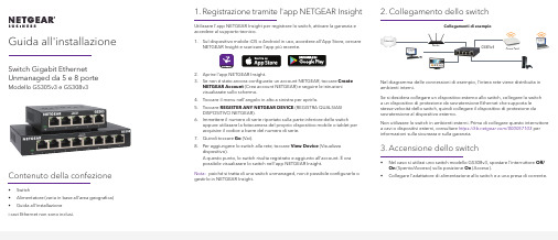
Guida all'installazione Switch Gigabit Ethernet Unmanaged da 5 e 8 porte Modello GS305v3 e GS308v3Contenuto della confezione• Switch• Alimentatore (varia in base all'area geografica)• Guida all'installazionei cavi Ethernet non sono inclusi.1. Registrazione tramite l'app NETGEAR InsightUtilizzare l'app NETGEAR Insight per registrare lo switch, attivare la garanzia eaccedere al supporto tecnico.1. Sul dispositivo mobile iOS o Android in uso, accedere all'App Store, cercareNETGEAR Insight e scaricare l'app più recente.2. Aprire l'app NETGEAR Insight.3. Se non è stato ancora configurato un account NETGEAR, toccare CreateNETGEAR Account (Crea account NETGEAR) e seguire le istruzionivisualizzate sullo schermo.4. Toccare il menu nell'angolo in alto a sinistra per aprirlo.5. Toccare REGISTER ANY NETGEAR DEVICE (REGISTRA QUALSIASIDISPOSITIVO NETGEAR).6. Immettere il numero di serie riportato sulla parte inferiore dello switchoppure utilizzare la fotocamera del proprio dispositivo mobile o tablet peracquisire il codice a barre del numero di serie.7. Quindi toccare Go (Vai).8. Per aggiungere lo switch alla rete, toccare View Device (Visualizzadispositivo).A questo punto, lo switch risulta registrato e aggiunto all'account. È orapossibile visualizzare lo switch nell'app NETGEAR Insight.Nota: poiché si tratta di uno switch unmanaged, non è possibile configurarlo ogestirlo in NETGEAR Insight.2. Collegamento dello switchNel diagramma delle connessioni di esempio, l'intera rete viene distribuita inambienti interni.Se si desidera collegare un dispositivo esterno allo switch, collegare lo switcha un dispositivo di protezione da sovratensione Ethernet che supporta lestesse velocità dello switch, quindi collegare il dispositivo di protezione dasovratensione al dispositivo esterno.Non utilizzare lo switch in ambienti esterni. Prima di collegare questo interruttorea cavi o dispositivi esterni, consultare https:///000057103 perinformazioni sulla sicurezza e sulla garanzia.3. Accensione dello switch• Nel caso si utilizzi uno switch modello GS308v3, spostare l'interruttore Off/On (Spento/Acceso) sulla posizione On (Acceso).•Collegare l'adattatore di alimentazione allo switch e a una presa di corrente.Access PointRouterGS305v3Collegamenti di esempioNETGEAR, Inc.piazza della Repubblica 32 20124 Milano NETGEAR INTL LTDFloor 1, Building 3, University Technology Centre Curraheen Road, Cork,T12EF21, Irlanda© NETGEAR, Inc. NETGEAR e il logo NETGEAR sono marchi di NETGEAR, Inc. Qualsiasi marchio non‑NETGEAR è utilizzato solo come riferimento.Supporto e CommunityVisita /support per trovare le risposte alle tue domande e accedere agli ultimi download.Puoi cercare anche utili consigli nella nostra Community NETGEAR, visitando la pagina .Conformità normativa e note legaliPer la conformità alle normative vigenti, compresa la Dichiarazione di conformità UE, visitare il sito Web https:///about/regulatory/.Prima di collegare l'alimentazione, consultare il documento relativo alla conformità normativa.I LED indicano lo stato.LED DescrizionePower (Alimentazione)• Acceso. Lo switch è collegato all'alimentazione.• Spento. Lo switch non è collegato all'alimentazione.Porta• Verde senza intermittenza. Lo switch ha rilevato uncollegamento con un dispositivo acceso su questa porta.• Lampeggia in verde. La porta invia o riceve traffico.• Spento. Lo switch non rileva nessun collegamento suquesta porta.Aprile 2020。
Infoprint 250 導入と計画の手引き 第 7 章ホスト

SUBNETMASK
255.255.255.128
Type of service...............: TOS
*NORMAL
Maximum transmission unit.....: MTU
*LIND
Autostart.....................:
AUTOSTART
*YES
: xx.xxx.xxx.xxx
: xx.xxx.xxx.xxx
*
(
)
IEEE802.3
60 1500
: xxxx
48 Infoprint 250
31. AS/400
IP
MTU
1
1
IPDS TCP
CRTPSFCFG (V3R2)
WRKAFP2 (V3R1 & V3R6)
RMTLOCNAME RMTSYS
MODEL
0
Advanced function printing............:
AFP
*YES
AFP attachment........................:
AFPATTACH
*APPC
Online at IPL.........................:
ONLINE
FORMFEED
*CONT
Separator drawer......................:
SEPDRAWER
*FILE
Separator program.....................:
SEPPGM
*NONE
Library.............................:
莫克A Fixed TTY 驱动程序用户指南说明书

This Tech Note applies to the following NPort device server models: •NPort DE-211•NPort DE-311•NPort DE-311M•NPort 5100 Series•NPort 5200 Series•NPort 5400 Series•NPort 5600 Series•NPort IA5150•NPort IA5250•NPort 6000 Series•NPort W2150•NPort W2150 Plus•NPort W2250•NPort W2250 Plus•NPort W2150A and NPort W2250A Series•NPort W2150A-W4/W2250A-W4 SeriesAll of these products support the following UNIX operating systems: •SCO UNIX•SCO OpenServer 5•SCO OpenServer 6•UnixWare 7•Solaris 10•QNX4.25•QNX6•FreeBSD 5.x•FreeBSD 6Installing the Fixed TTY Driver for NPortBefore performing the following steps, restore the NPort's default settings by holding down the reset button for 10 seconds.1.Make sure that DIP switch 1 is set to OFF (applies to DE-211 and DE-311).2.Modify the DIP switch settings for serial communication as required for your device.3.Turn on the NPort. The Ready LED should turn green.4.Make sure that the NPort and the host PC are properly connected to the network.5.Adjust the NPort's IP settings so that it is on the same subnet as your PC. You may10.Follow your operating system's instructions for compiling and linking the source files:QNX4 # make qnx4QNX6 # make qnx6SCO OpenServer 6 # make sco6SCO OpenServer 5 # make scoSolaris # make sunFreeBSD # make freebsdUnixWare 7 # make svr511.Verify that the configuration is correct by using a text editor (vi, for example) to openthe text file moxattyd.cf, which is in the directory that contains the moxattyddeamon. The IP:port mapping for TTY devices will appear as shown below:ttyp11 192.168.127.254 950e the following command to start the moxattyd daemon:# /usr/etc/moxattyd/moxattyd –t 1The optional "-t" parameter is used to show the connection timeout value, measuredin minutes.13.To start the moxattyd daemon automatically on system bootup, add an entry to theappropriate system file. For SCO OpenServer 5 and 6, Solaris, and UnixWare 7, addthe following entry to the file /etc/inittab:ts:234:respawn:/usr/etc/moxattyd/moxattyd -t 1For QNX4, QNX6, and FreeBSD, add an entry to the appropriate system file asfollows:OS File Add this entryQNX4 /etc/Config/sysinit.1QNX6 /etc/rc.d/rc.local/usr/etc/moxattyd/moxattyd –t 1 FreeBSD /etc/rc.local3Testing Fixed TTY Ports1.After installing the Fixed TTY driver as described above, enter the following commandto verify that a TTY port is available:# sty –a < /dev/ttyp12.If the system responds with some serial parameter(s), the TTY port is available andcan be accessed by other programs.。
千兆光猫用户手册说明书

The CODA-5519is a powerful router that will be used as the heart of your wireless home.It will offer strong Wi-Fi that will covers most houses.The CODA-5519has the capability to receive 5Gbps bi-directional based on 2OFDM +32QAM downstream channels and with 2OFDMA +8upstream channels over its DOCSIS 3.1interface.The integrated Wi-Fi 4x42.4GHz 802.11ax and 4x45GHz 802.11ax dual band MU-MIMO Access Point significantly improves customer experience extending range and coverage with blazing speeds.For wired clients,2.5G plus two Gigabit Ethernet ports offer ultra-fast connection.It can be paired with Hitron extenders/mesh pods for extra coverage.•DOCSIS 3.1 2x2 multi-carrier OFDM •DOCSIS 3.0 32x8 channel bonding•4x4 2.4GHz 802.11ax and 4x4 5GHz 802.11ax dual band concurrent MU-MIMO internal antennas •16 SSIDs (8SSIDs per radio)•Individual configuration for each SSID (security, bridging, routing, firewall and Wi-Fi parameters)•Extensive operator control via configuration file and SNMP•Integrated DLNA Media Server with support for video, audio and image servingDOCSIS 3.1 Wi-Fi 6 and eMTA GatewayIntel® Puma™ 7 OFDM 2x2 w / fixed upstream, 4x4 dual band Wi-Fi w/ concurrent 802.11ax 2.4Ghz + 5GHz, MoCA 2.0 channel bonding and voice HIGH PERFORMANCE INTERNET AND WIRELESS ACCESSThe CODA-5519supports pre-configured and pre-enabled Wi-Fi security via Wi-Fi Protected Setup (WPS),allowing the end-user to rapidly set up a secure wireless network without manual configuration.Hitron's AutoSync software provides secure automated setup of extenders in the customer's home or business.It comes with MyHitron (end user management mobile application).MSO can also get extra management and analytics via HitronCloud/OptiMy CSR interface from the support center.SECURE WIRELESS NETWORKING CONTROLLED AT THE TIP OF YOUR FINGERSKEY FEATURES•IPv6 routing•MoCA 2.0 channel bonding•TR-069 and HNAP for easy setup and remote management•Enhanced management and stability for low total cost of ownership•One 2.5G and Two 1G Ethernet ports •Hitron Ecosystem Support (OptiMy, HitronCloud, MyHitron)•2 HD voice ports with SIP or MGCP supportTVStreamer Smartphone TabletThermostatHome Security LaptopCODA-5519Printer PCMoCA ExtenderPhonesWi-Fi1G Ethernet Analog2.5G Ethernet Coax PodLaptop Gaming ConsoleConnectivity•RF F-Type 75Ωfemale connector•2x RJ-45 Ethernet port 10/100/1000Mbps•1x RJ-45 Ethernet port 10/100/1000/2500Mbps•USB 3.0 type A connector with host interface•2x RJ-11 HD voice ports•EBBU jackManagement•Protocol support: TR-069, TFTP, SSHv2, SNMP v2C, v3•Web-based GUI control, configuration and management •Power-on self diagnostic•Hitron proprietary MIBs for extended support onDOCSIS, router management, Wi-Fi managementand MoCA management•app support•and back end supportReception-Demodulation•DOCSIS 3.1/3.0/2.0•DOCSIS 3.1 demodulation: Multi-carrier OFDM 16 to 4096QAM •DOCSIS 3.1 data rate: Up to 5Gps with 2 OFDM 192MHz downstream channels +32 QAM•DOCSIS 3.0 demodulation: 64QAM, 256QAM•DOCSIS 3.0 data rate: Up to 1.2Gbps with 32 bonded downstream channels•Frequency (edge-to-edge): 108-1218MHz and 258-1218 •Channel Bandwidth: 6MHz•Signal level: -15dBmV to 15dBmVTransmitter-Modulation•DOCSIS 3.1/3.0/2.0•DOCSIS 3.1 modulation: Multi-carrier OFDMA BPSK to 4096QAM •DOCSIS 3.1 data rate: Up to 700Mbps with OFDMA 96MHz upstream channels•DOCSIS 3.0 modulation: QPSK, 8QAM, 16QAM, 32QAM, 64QAM, and 128QAM (SCDMA only)•DOCSIS 3.0 data rate: Up to 320Mbps with 8 bonded upstream channels•Frequency: Fixed 5-85MHz•Upstream transmit signal level: +11 to 65dBmVMoCA 2.0 Reception / Transmitter-Modulation •Demodulation/ Modulation: BPSK, QPSK, 8QAM, 16QAM,32QAM, 64QAM, 128QAM, 256QAM, 512QAM, 1024QAM •PHY data rate: 700Mbps (baseline Mode) / 1400Mbps (bonding channel)•Throughput: 400+Mbps (baseline mode) / 500+Mbps (turbo mode, point to point) / 800Mbps (bonding channel)•Frequency (center frequencies): 1400-1625MHz•Channel bandwidth: 100MHz (baseline mode) / 225MHz (bonding channel)Voice•Protocol support: SIP or MGCP•2x 8kHz each HD voice•Audio codecs: G.711 (a-law and mu-law), G.722 (HD codec), G.723.1, G.726, G.728, and G.729Routing Support•Protocol support: IGMP v3 for IPTV service capability•MAC address filtering (IPv4/IPv6)•IP source/destination address filtering (IPv4/IPv6)•DHCP, TFTP and ToD clients (IPv4/IPv6)•DHCP server supports RFC 1541 (IPv4)•DHCPv6 obtains prefix from DHCPv6 server through prefix delegation•Firewall with stateful inspection (IPv4/IPv6)•Hacker intrusion prevention and detection•Application content filtering (IPv4/IPv6)•Complete NAT software implemented as per RFC 1631 with port and address mapping (IPv4)•DSLite support for IPv4 in-home support with IPv6 MSO backbone •6RD support for quick IPv6 deployment over IPv4 backbone •RIPv2 for static IP supportWireless•802.11a/b/g/n/ac/ax•4T4R 2.4GHz 11ax and 4T4R 5GHz 11ax dual band concurrent MU-MIMO with 1Gbps+4.8Gbps PHY rate•20/40/80/160MHz channel bandwidth•Up to 8 SSIDs for each frequency•Security: WPA-PSK/WPA2-PSK (TKIP/AES), WPA3, WAPI •QoS: WMM/WMM-PS•WPS (Wi-Fi Protected Setup) PBC, PIN•Airtime Fairness (ATF), Band Steering (BS)•Dynamic Frequency Selection (DFS)•Wi-Fi output power range: Max permitted by FCC/IC Electrical•Input power: 12VDC, 4A•Power adaptor: 100-240VAC, 50/60Hz•Power consumption: 4.92 (power saving), 22W (typ.), 38W (Max)•Support power outage for 24 hours on Hitron external battery •Surge protection: RF input sustains at least 4KVEthernet RJ-45 sustains at least 4KV Mechanical•Factory default reset button•WPS button•Dimensions: 74.3mm (W) x 251.5mm (H) x 230.8mm (D)•Weight: Weight: 1850 ±10gEnvironmental•Operating temperature: 0°C (32°F) ~ 40°C (104°F)•Operating humidity: 10% ~ 90% (Non-condensing)•Storage temperature: -40°C (-40°F) ~ 60°C (140°F) Compliance Certificates•RoHS compliant•FCC, IC, ULSPECIFICATIONS。
- 1、下载文档前请自行甄别文档内容的完整性,平台不提供额外的编辑、内容补充、找答案等附加服务。
- 2、"仅部分预览"的文档,不可在线预览部分如存在完整性等问题,可反馈申请退款(可完整预览的文档不适用该条件!)。
- 3、如文档侵犯您的权益,请联系客服反馈,我们会尽快为您处理(人工客服工作时间:9:00-18:30)。
Cap 548A s 5 Owner to notify Director of change in ownership四摘要:本文主要介绍了Cap 548A s 5 Owner to notify Director of change in ownership主要内容。
摘要:本文主要介绍了CAP 548A MERCHANT SHIPPING (LOCAL VESSELS) (DWELLING VESSELS) REGULATION的主要内容。
(a) seize the vessel;(b) remove the vessel or cause it to be removed from the closed area or the prescribed area, as the case may be;(c) detain the vessel.(5) Where a vessel has been seized and detained under subsection(4), and regardless of whether the vessel has been removed under that subsection, the Director may remove any person or property found on the vessel and may take possession of any property found on the vessel.(6) As soon as practicable after seizing and detaining a vessel under subsection (4), and regardless of whether the vessel has been removed under that subsection, the Director shall serve a notice of the seizure and detention on the persons whom the Director believes to be the owner and the licensee of the vessel, and on every person whom the Director believes to be the owner or otherwise entitled to the possession of any property on board the vessel.(7) A notice served under subsection (6) shall be deemed to have been duly served on the person on whom it is to be served-(a) if the notice is delivered to the person concerned;(b) if the notice is sent by registered post addressed to that person at the place of residence or business of that person, if any, last known to the Director; or(c) (where it cannot be served in accordance with paragraph (a) or (b)) if the notice is published in the Gazette.(8) A notice served under subsection (6) shall-(a) state the names (if known to the Director) of the persons whom the Director believes to be the owner and the licensee of the vessel;(b) state the name (if known to the Director) of every person whom the Director believes to be the owner or otherwise entitled to the possession of any property on board the vessel;(c) describe the vessel and the place at which it was seized;(d) describe the property on board the vessel;(e) give the reason for the seizure and detention of the vessel;(f) specify the position where the vessel is secured, anchored or moored during its detention;(g) specify the action (if any) required to secure the release of the vessel or any property on board the vessel; and(h) specify the period (being not less than 14 days) within which a claim may be submitted to the Director for the release of the vessel or any property on board the vessel, and the place at which such a claim may be submitted.(9) The Director may, for the purposes of subsection (8)(g), specify any action required to secure the release of a vessel or any property on board the vessel, and any such action may include the payment of any expense incurred as a result of or in connection with any action taken or caused to be taken by the Director under this section in respect of the vessel or the property in question, as the case may be.(10) A person who obstructs the Director in the exercise of any of the powers conferred by subsection (4) or (5) commits an offence and is liable on conviction to a fine at level 2 and to imprisonment for 6 months.Cap 548A s 17 Release of detained vessels, etc.Remarks:not yet in operation(1) A claim for the release of a vessel that is the subject of a notice served under section 16(6), or for the release of any property on board the vessel, may be submitted to the Director, subject to compliance with the following requirements—(a) the claim shall be submitted, in the case of a claim for the release of the vessel, by the owner or licensee of the vessel and, in the case of a claim for the release of anyproperty on board the vessel, by the person who is the owner or otherwise entitled to the possession of the property in question; and(b) the claim shall be submitted within the period and at the place specified in the notice.(2) If a claim is submitted to the Director for the release of a vessel that is the subject of a notice served under section 16(6) or for the release of any property on board the vessel, and if the Director is satisfied that the claim is submitted in accordance with the requirements set out in subsection (1) and that the action specified in the notice under section 16(8)(g) in respect of the vessel or the property in question, as the case may be, has been carried out, then the Director shall release the vessel or the property in question, as the case may be, to the claimant.Cap 548A s 18 Sale of detained vessels, etc.Remarks:not yet in operation(1) If a vessel that is the subject of a notice served under section 16(6) is not released pursuant to section 17(2), the Director may sell the vessel by public auction or otherwise as he thinks fit.(2) The proceeds of sale of a vessel sold under subsection (1), after deducting all expenses incurred as a result of or in connection with the seizure, removal, detention and sale of the vessel, shall be paid to the owner of the vessel if he claims them within 1 yearafter the date of the sale, or forfeited to the Government if the owner of the vessel does not claim them within that period.(3) A vessel that the Director is unable to sell under subsection (1) may be destroyed or otherwise disposed of as the Director thinks fit.(4) If any property on board a vessel that is the subject of a notice served under section 16(6) is not released pursuant to section 17(2), such property shall become the property of the Government free from the rights of any person and may be disposed of by the Director as he thinks fit.Cap 548A s 19 AppealsRemarks:not yet in operation(1) Any person aggrieved by a decision of the Director-(a) to specify any condition in a licence under section 3(5);(b) to make any amendment or addition to the conditions specified in a licence under section 3(6);(c) to refuse to renew a licence under section 4(3)(b);(d) to refuse to transfer a licence under section 7(4)(b);(e) to cancel a licence under section 8;(f) to refuse to permit the replacement of a vessel under section 13;(g) to specify any action required to secure the release of a vessel or any property on board the vessel under section 16(9); or(h) to refuse to release a vessel or any property on board the vessel under section 17(2),may, within 14 days after the day on which he is informed of the decision, appeal to the Administrative Appeals Board against the decision.(2) If a decision referred to in paragraph (a), (b), (c), (d), (e) or (f) of subsection (1) is appealed against under that subsection, the decision concerned shall be suspended in its operation from the day on which notice of the appeal is lodged until the appeal is disposed of, withdrawn or abandoned, unless such suspension would, in the opinion of the Director, be contrary to the public interest and the notice of that decision containsa statement to that effect.(3) If a decision referred to in paragraph (g) of subsection (1) is appealed against under that subsection, then, as against the person making the appeal-(a) the period within which a claim may be submitted to the Director for the release of the vessel concerned or any property on board that vessel, specified in the notice served in respect of that vessel under section 16(6), shall not begin to run until the appeal is disposed of, withdrawn or abandoned; and(b) the notice shall otherwise have effect subject to the outcome of the appeal.(4) If a decision referred to in paragraph (h) of subsection (1) is appealed against under that subsection, the decision concerned shall be suspended in its operation from the day on which notice of the appeal is lodged until the appeal is disposed of, withdrawn or abandoned.Cap 548A s 20 Amendment of SchedulesRemarks:not yet in operationThe Director may, by notice published in the Gazette, amend either or both of the Schedules. Cap 548A Sched 1 CLOSED AREASRemarks:not yet in operation[sections 2 & 20]All waters of Hong Kong except Causeway Bay Typhoon Shelter and Cheung Chau Typhoon Shelter. Cap 548A Sched 2 PRESCRIBED AREASRemarks:not yet in operation[sections 2 & 20]Causeway Bay Typhoon Shelter Cheung Chau Typhoon Shelter。