Tutorial_02_Scaling_Wedge_Size
opencv的双目立体校正函数

opencv的双目立体校正函数OpenCV(开源计算机视觉库)提供了一系列功能强大的函数,用于处理双目立体视觉任务。
其中一个关键函数是双目立体校正函数(stereoRectify),它在立体视觉中用于消除摄像机畸变并将两个摄像机的图像校正到一个共同的平面上。
本文将从头开始一步一步解释这个函数的操作。
第一步:导入必要的库和模块首先,需要导入OpenCV库和其他需要的库和模块。
在Python中,可以使用以下代码导入这些库:pythonimport cv2import numpy as np第二步:定义相机参数和视差参数在进行双目立体校正之前,需要定义每个摄像机的参数和视差参数。
这些参数包括相机内参、相机畸变系数、旋转矩阵和投影矩阵等。
为了简化说明,我们这里使用一个简化的示例参数:python# 相机内参cameraMatrix1 = np.eye(3)cameraMatrix2 = np.eye(3)# 相机畸变系数distCoeffs1 = np.zeros((5, 1))distCoeffs2 = np.zeros((5, 1))# 至关重要的矩阵R = np.eye(3)T = np.zeros((3, 1))这些参数是根据相机特性和摄像机标定过程获得的。
在实际应用中,应根据具体情况相应地设置这些参数。
第三步:计算校正变换矩阵通过使用上述相机参数和视差参数,可以计算出双目立体校正所需的校正变换矩阵。
校正变换矩阵将两个摄像机的图像校正到一个共同的平面上。
在OpenCV中,可以使用以下代码计算校正变换矩阵:python# 计算校正变换矩阵及其逆矩阵rectifyScale = 1 # 校正后图像的缩放因子R1, R2, P1, P2, Q, validPixROI1, validPixROI2 =cv2.stereoRectify(cameraMatrix1, distCoeffs1, cameraMatrix2, distCoeffs2, imageSize, R, T, rectifyScale)在上述代码中,imageSize是输入图像的大小。
OpenCv参考手册-CvImage类参考手册
OpenCv参考手册-CvImage类参考手册CvImage类参考手册Wikipedia,自由的百科全书CvImage使用前需要包含 cv.h 头文件#include目录1 CvImage::CvImage2 CvImage::~CvImage3 CvImage::clone4 CvImage::create5 CvImage::release6 CvImage::clear7 CvImage::attach8 CvImage::detach9 CvImage::load10 CvImage::read11 CvImage::save12 CvImage::write13 CvImage::show14 CvImage::is_valid15 CvImage::width16 CvImage::height17 CvImage::size18 CvImage::roi_size19 CvImage::roi20 CvImage::coi21 CvImage::set_roi22 CvImage::reset_roi23 CvImage::set_coi24 CvImage::depth25 CvImage::channels26 CvImage::pix_size27 CvImage::data28 CvImage::step29 CvImage::origin30 CvImage::roi_row31 运算符重载32 编写者[编辑]CvImage::CvImagebool CvImage::CvImage();bool CvImage::CvImage(CvSize size, int depth, int channels);bool CvImage::CvImage(IplImage* pIplImg);bool CvImage::CvImage(const CvImage& cvImg);bool CvImage::CvImage(const char* filename, const char* imgname=0, int color=-1);bool CvImage::CvImage(CvFileStorage* fs, const char* mapname, const char* imgname);bool CvImage::CvImage(CvFileStorage* fs, const char* seqname, int idx);默认构造函数,创建一个图像。
sklearn.calibration训练python例程

sklearn.calibration训练python例程以下是使用sklearn.calibration进行模型校准的Python例程:```pythonimport numpy as npfrom sklearn.datasets import load_irisfrom sklearn.model_selection import train_test_splitfrom sklearn.calibration import CalibratedClassifierCVfrom sklearn.metrics import accuracy_score# 加载数据集iris = load_iris()X = iris.datay = iris.target# 将数据集分为训练集和测试集X_train, X_test, y_train, y_test = train_test_split(X, y, test_size=0.2, random_state=42)# 创建一个随机分类器clf = MLPClassifier(hidden_layer_sizes=(100,), activation='relu',solver='adam', max_iter=300)# 对分类器进行校准calibrated_clf = CalibratedClassifierCV(clf, cv=3)calibrated_clf.fit(X_train, y_train)# 在测试集上进行预测y_pred = calibrated_clf.predict(X_test)# 计算准确性accuracy = accuracy_score(y_test, y_pred)print('Accuracy after calibration:', accuracy)```在这个例程中,我们首先导入了所需的库和函数。
2024 python与机器视觉教程

2024 python与机器视觉教程以下是一个关于Python与机器视觉的教程,不包含标题:一、介绍Python是一种高级编程语言,广泛应用于数据分析、人工智能和机器学习等领域。
机器视觉是一种模拟人类视觉的技术,引入计算机和摄像设备,通过图像处理和模式识别等方法来实现各种应用。
二、安装Python1. 下载Python安装包:在Python官方网站上找到适合您操作系统的安装包,点击下载。
2. 运行安装程序:双击安装包,按照提示进行安装。
选择默认选项即可。
三、安装机器视觉库1. 安装OpenCV库:OpenCV是一个开源的计算机视觉和机器学习软件库,提供了Python接口。
通过以下命令在命令行中安装OpenCV库:```pip install opencv-python```2. 安装Pillow库:Pillow是一个用于处理图像的Python库,可以进行图像读取、处理和保存等操作。
通过以下命令在命令行中安装Pillow库:```pip install pillow```四、加载图像在Python中,可以使用OpenCV库来加载和处理图像。
下面是一个示例代码:```pythonimport cv2# 读取图像image = cv2.imread('image.jpg')# 显示图像cv2.imshow('Image', image)cv2.waitKey(0)cv2.destroyAllWindows()```五、图像处理使用OpenCV库可以进行各种图像处理操作,如缩放、旋转、边缘检测等。
下面是一个示例代码:```pythonimport cv2# 读取图像image = cv2.imread('image.jpg')# 缩放图像resized_image = cv2.resize(image, (500, 500))# 旋转图像rotated_image = cv2.rotate(resized_image,cv2.ROTATE_90_CLOCKWISE)# 边缘检测gray_image = cv2.cvtColor(rotated_image,cv2.COLOR_BGR2GRAY)edges = cv2.Canny(gray_image, 100, 200)# 显示图像cv2.imshow('Edges', edges)cv2.waitKey(0)cv2.destroyAllWindows()```六、图像识别通过机器学习和模式识别算法,可以使用Python进行图像识别任务。
SCALE用户指南说明书

(SCALE用户指南)5.3.5 版本SCALE 团队UGC 工作区,2020 年 1 月 21 日目录1概述2 1.1简介31.1.1什么是 SCALE? (3)1.1.2SCALE-RM 结构 (5)1.2本文档中使用的符号72安装8 2.1准备92.1.1系统环境 (9)2.2编译 SCALE122.2.1下载环境设置 (12)2.2.2编译 (13)2.3编译后处理工具 (net2g)152.3.1编译 netcdf2grads (net2g) (15)3SCALE-RM 教程16 3.1操作检查和基本使用173.1.1简介 (17)3.1.2如何执行模型 (17)3.1.3后处理与绘图 (19)3.1.4后续研究指南 (20)3.2真实大气试验223.2.1概述 (22)3.2.2准备输入数据(边界数据) (23)3.2.3准备试验集 (25)3.2.4创建地形数据:pp (26)3.2.5创建初始和边界数据:init (27)3.2.6执行模拟:run (29)3.2.7快速查看模拟结果:net2g (33)第 1 部分概述第 1.1 章简介此用户手册面向初次使用区域气候/气象模型 SCALE-RM 的用户。
本手册基于 5.3.5 版本的数值程序库。
尽管当前版本的 SCALE 包含区域模型 SCALE-RM 和全球模型 SCALE- Gm,此版本用户手册仅阐述如何使用 SCALE-RM。
下一个或更后面的发行版本将阐述 SCALE-GM。
本文档的结构如下:第1 部分提供 SCALE 的概述,第2部分阐述如何安装 SCALE-RM 以及有何系统要求。
而第3 部分通过一系列教程阐述 SCALE-RM 的基本使用;第3.1 和第3.2章分别提供理想试验教程和真实大气试验。
建议 SCALE-RM 初学者仔细阅读这些章节。
有关如何更改模型配置、数据格式以及可用功能和工具的详细信息,请参考《SCALE 用户指南》英文版(EN 版本)的第 4 和第 5 部分。
多尺度卷积代码

多尺度卷积代码多尺度卷积是一种非常有用的计算机视觉算法,它可以帮助我们获得更准确的图像分类和目标检测结果。
在本文中,我们将重点介绍多尺度卷积的代码实现,以及如何在实际应用中使用它。
第一步:安装必要的库要使用多尺度卷积,我们需要安装一些必要的库,例如PyTorch 和NumPy。
这些库可以在Python环境下很容易地安装,可以使用pip 命令完成。
安装完成后,我们可以使用以下代码导入库:import torchimport numpy as np第二步:编写多尺度卷积代码多尺度卷积通常包括两个步骤。
首先,我们需要对图像进行多尺度变换,例如使用不同大小的滤波器,或将图像缩小。
其次,我们需要在每个尺度上应用卷积操作。
以下是一个简单的多尺度卷积代码示例:def multiscale_conv(image, filter_sizes, num_filters): """Apply a set of convolutions at multiple scales to an input image,and concatenate the results."""# Apply convolutions at multiple scalesoutputs = []for size in filter_sizes:conv = torch.nn.Conv2d(3, num_filters, size,padding=size//2)output = conv(image)outputs.append(output)# Resize outputs to a common sizeshape = min(output.shape[2:])outputs = [torch.nn.functional.interpolate(o, shape, mode='bilinear', align_corners=False) for o in outputs]# Concatenate outputsoutput = torch.cat(outputs, axis=1)return output在该代码中,我们首先定义了一个multiscale_conv函数,它接受一个图像、滤波器大小列表和过滤器数量作为输入。
openai 微调训练例子
openai 微调训练例子OpenAI的微调训练是一个复杂的过程,以下是一个例子:1. 创建一个微调模型:基于达芬奇模型,创建一个自己的模型。
只有几种模型可以训练,例如ada、babbage、curie、davinci。
使用OpenAI API fine_命令,需要指定数据文件路径和基础模型。
例如:```openai api fine_ -t /Users/szz/app/1_ -m davinci```2. 列出所有微调任务的列表:使用openai api fine_命令,可以查看所有已创建的微调任务,状态可能是pending(待处理)、running(正在训练)、succeeded(成功)或failed(失败)。
3. 获取微调任务的状态:使用openai api fine_命令,后跟任务ID,可以获取特定微调任务的状态和其他信息。
例如:```openai api fine_<YOUR_FINE_TUNE_JOB_ID>```4. 取消微调任务:使用openai api fine_命令,后跟任务ID,可以取消特定微调任务。
例如:```openai api fine_<YOUR_FINE_TUNE_JOB_ID>```5. 使用微调模型:一旦微调训练完成并成功,可以使用OpenAI CLI的命令来使用微调模型。
需要指定微调模型和输入提示。
例如:```openai api -m<FINE_TUNED_MODEL>-p<YOUR_PROMPT>```请注意,以上步骤可能会因为OpenAI API版本和具体使用情况而有所不同。
建议参考OpenAI官方文档或API指南以获取更详细和准确的信息。
Matlab标定工具箱的使用
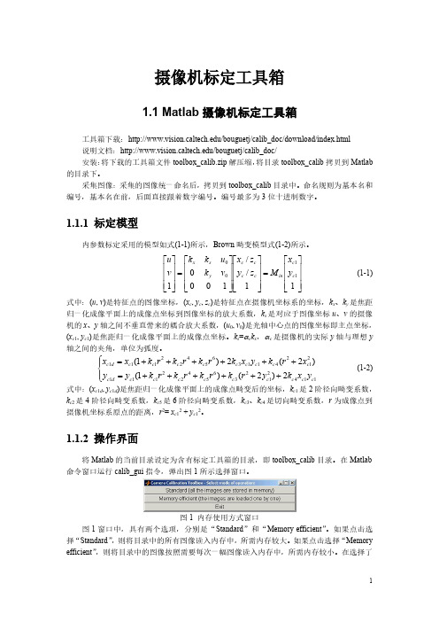
1
内存使用方式后,弹出标定工具箱操作面板。图 2 是选择“Standard”后弹出的标定工具箱 操作面板。
图 2 标定工具箱操作面板 图 2 所示的标定工具箱操作面板具有 16 个操作命令键,其功能如下: (1) “Image names”键:指定图像的基本名(Basename)和图像格式,并将相应的图像读 入内存。 (2) “Read names”键:将指定基本名和格式的图像读入内存。 (3) “Extract grid corners”键:提取网格角点。 (4) “Calibration”键:内参数标定。 (5) “Show Extrinsic”键:以图形方式显示摄像机与标定靶标之间的关系。 (6) “Project on images”键:按照摄像机的内参数以及摄像机的外参数(即靶标坐标系 相对于摄像机坐标系的变换关系),根据网格点的笛卡尔空间坐标,将网格角点反投影到图 像空间。 (7) “Analyse error”键:图像空间的误差分析 (8) “Recomp. corners”键:重新提取网格角点。 (9) “Add/Suppress images”键:增加/删除图像。 (10) “Save”键:保存标定结果。将内参数标定结果以及摄像机与靶标之间的外参数 保存为 m 文件 Calib_results.m,存放于 toolbox_calib 目录中。 (11) “ Load ”键: 读入标定 结果。从 存放于 toolbox_calib 目录 中的标定 结果文件 Calib_results.mat 读入。 (12) “Exit”键:退出标定。 (13) “Comp. Extrinsic”键:计算外参数。 (14) “Undistort image”键:生成消除畸变后的图像并保存。 (15) “Export calib data”键:输出标定数据。分别以靶标坐标系中的平面坐标和图像中 的图像坐标,将每一幅靶标图像的角点保存为两个 tex 文件。 (16) “Show calib results”键:显示标定结果。
- 1、下载文档前请自行甄别文档内容的完整性,平台不提供额外的编辑、内容补充、找答案等附加服务。
- 2、"仅部分预览"的文档,不可在线预览部分如存在完整性等问题,可反馈申请退款(可完整预览的文档不适用该条件!)。
- 3、如文档侵犯您的权益,请联系客服反馈,我们会尽快为您处理(人工客服工作时间:9:00-18:30)。
Scaling Wedges TutorialUnwedge always initially calculates the maximum sized wedges which can form around an excavation.This tutorial demonstrates how to scale down the size of the wedges, to represent the actual size of wedges observed in the field. This is donewith the Scale Wedges option, which allows you to scale the size of wedges according to field measurements such as joint trace lengths, joint persistence, wedge face area etc.Wedge scaling is important because the assumed wedge size can have a significant effect on support requirements (e.g. pattern spacing, positioning or orientation of bolts, and the thickness or strength of shotcrete).The model represents a section of an underground spiral access ramp.Topics Covered•Scaling Wedge Size•Scaling All Wedges•Scaling Individual Wedges•Safety factor and ScalingModelFor this tutorial we will start by reading in the file Tutorial 02 ScalingWedges.weg which you should find in the Examples > Tutorials folder inyour Unwedge installation folder.Select: File → OpenNavigate to the Examples > Tutorials folder in your Unwedge installationfolder and open the Tutorial 02 Scaling Wedges.weg file.The model should appear as follows.Figure 1: Maximum sized perimeter wedges for tutorial 2 example.As you can see, all of the Perimeter Wedges (roof, sides and floor wedges)are the maximum possible size for the excavation cross-section.NOTE: the Plunge of the Tunnel Axis Orientation is 15 degrees, becausethe model represents a section of an inclined ramp, rather than ahorizontal tunnel.Scaling WedgesTo scale down the size of wedges, select the Scale Wedges option fromthe Analysis menu.Select: Analysis → Scale WedgesYou will see the Scale Wedges dialog.Wedge size can be scaled according to joint trace length, joint persistenceor wedge data (e.g. volume, face area etc). Although we can entermultiple scaling parameters at the same time, let’s enter parameters oneat a time, to see the results at each step.Select the Joint 1 (Trace Length) checkbox, and enter a Scaling Value of 4meters. Select OK.Your screen should look as follows.Figure 2: Wedge size scaled by Joint 1 trace length = 4 meters.Notice that all of the wedges have been scaled down in size. To indicate that scaling has been applied to a wedge, the letter “s” is displayed beside the wedge number (e.g. the roof wedge is numbered “8s”). NOTE: if you do not see the wedge numbers, go to Display Options, select the Wedge View tab, and make sure the Wedge Numbers checkbox is selected.Before we proceed further, select the Filter List button in the Sidebar.1.In the Wedge Information Filter dialog, select the Defaultsbutton (so that only the Wedge Name, Factor of Safety andWedge Weight checkboxes are selected).2.Now select the Scaled By checkbox and the Joint TraceLengths checkbox, as shown in the following figure. Select OK.Now look at the Wedge Information panel in the Sidebar. NOTE: •For all wedges, Scaled By = Joint 1 Trace Length•For all wedges, Joint 1 Trace Length = 4 meters.This is consistent with the single scaling value which we entered in the Scale Wedges dialog (Joint 1 Trace Length = 4 meters).At this point, we should note the following:•When we use the All Wedges scaling option (in the Scale Wedges dialog), this does not necessarily mean that all wedges will bescaled (i.e. reduced in size). It means that all wedges will beCONSIDERED for scaling. Wedges will only be scaled if theircurrent dimensions are larger than one of the scaling parameters.If the parameters of a wedge are already smaller than the scalingparameters, then the wedge will not be affected by the scaling.In the current example, all of the wedges were reduced in size, but ingeneral this will not necessarily be the case.Figure 3: Wedge information after scaling by Joint 1 trace length.Now let’s enter one more scaling parameter.Select: Analysis → Scale WedgesIn the Scale Wedges dialog, select the Joint 2 (Trace Length) checkbox, and enter a Scaling Value of 4 meters. Select OK.Look at the Wedge Information panel in the Sidebar. The results are now as follows:•For the Floor Wedge and the Roof Wedge, Scaled By = Joint 2 Trace Length, and Joint 2 Trace Length = 4 meters.•For the Lower Left and Lower Right wedges, Scaled By = Joint1 Trace Length, and Joint 1 Trace Length = 4 meters.For the Floor and Roof wedges, the Joint 2 trace length (scaling value) is now the governing parameter (the Joint 1 trace length is less than 4 meters).For the Lower Left and Lower Right wedges, the Joint 1 trace length (scaling value) is still the governing parameter, since the Joint 2 trace lengths are already less than 4 meters, therefore the Joint 2 trace length scaling value does not affect these wedges.This illustrates the following important points:•When you enter more than one Scaling Value, a given wedge is ultimately scaled by only one parameter – the parameter whichgives the smallest wedge size.•Furthermore, if Wedges to Scale = All Wedges (in the Scale Wedges dialog), and you have entered multiple scaling values, thegoverning scaling parameter can be different for different wedges. Let’s enter a third scaling parameter.Select: Analysis → Scale WedgesIn the Scale Wedges dialog, select the Joint 3 (Trace Length) checkbox, and enter a Scaling Value of 4 meters. Select OK.Look at the Wedge Information panel in the Sidebar:•For all wedges, Scaled By = Joint 3 Trace Length•For all wedges, Joint 3 Trace Length = 4 meters.The Joint 3 Trace Length scaling value (4 meters) is now the governing scaling parameter for all wedges. Notice that the actual Joint 1 and Joint 2 trace lengths for all wedges are now less than 4 meters.Figure 4: Wedge size scaled by Joint 3 trace length = 4 meters.NOTE: if you go back to the Scale Wedges dialog, and turn OFF the checkboxes for Joint 1 Trace Length and Joint 2 Trace Length, and select OK, the results will not change, since the Joint 3 Trace Length scaling value gives the smallest wedge size for all perimeter wedges.Position of Scaled WedgesFor perimeter wedges which span multiple segments of the Opening Section (e.g. the Roof wedge in this example), Unwedge uses an algorithm which searches for the wedge with the maximum volume for the given Scaling Value(s). An iterative process is required to find this wedge. This determines the position of the scaled wedge on the perimeter.In this example, if you compare Figure 2 and Figure 4, notice that the Roof Wedge is off to one side in Figure 2 and is approximately centered in Figure 4. The different positions of the Roof Wedge are due to the Unwedge searching algorithm and the different scaling values used for each case.For wedges which are formed on a single flat surface of the excavation boundary, the searching algorithm is not applicable, and the scaledwedge position will be approximately centered on the surface.Scaling Individual WedgesSo far in this tutorial, we have considered all wedges for scaling, using the same set of scaling values (i.e. in the Scale Wedges dialog, the Wedge to Scale option was set to All Wedges).It is also possible to consider individual wedges for scaling. This allows you to enter independent scaling values for any desired wedge(s). To select individual wedges for scaling:•You can select the desired wedge from the Wedge to Scale drop-list in the Scale Wedges dialog.•You can also right-click directly on a wedge, and select Scale Wedge for that particular wedge from the popup menu, as shownin the following figure. This will display the Scale Wedges dialogwith the wedge already selected in the dialog.For example:1.Right-click on the Roof Wedge, and select Scale Wedge: 8 Rooffrom the popup menu, as shown in the above figure.2.In the Scale Wedges dialog, select the Joint 2 Trace Lengthcheckbox and enter a scaling value of 3 meters. Select OK.3.Now look at the Wedge Information panel. The Roof wedge is nowscaled by the Joint 2 Trace Length = 3 meters. All other wedgesare still scaled according to the Joint 3 Trace Length scalingvalue entered with the All Wedges scaling option.Figure 5: Roof wedge scaled independently using Joint 2 Trace Length = 3.You can scale any or all wedges individually, in this manner. When you select individual wedges to scale, the Scaling Value parameters are entered independently for each wedge, and the dialog will “remember” the Scaling Values you have entered for each wedge.NOTE: if you specify Scaling Values for All Wedges, AND for individual wedges, at the same time in the Scale Wedges dialog, the program will use the Scaling Value which gives the smallest wedge, for any given wedge.Resetting the Maximum Wedge SizeTo reset all wedges to the maximum size, select the Maximize button in the Scale Wedges dialog. This will clear all of the Scaling Values, for All Wedges and also for any individual wedge Scaling Values you have entered.Scaling Wedges Tutorial 2-11 Unwedge v.3.0 Tutorial Manual Safety Factor and ScalingWe will now briefly discuss the effect of scaling the wedge size on the wedge safety factor and support requirements. Effect of Joint Strength• Frictional Strength Only – if the shear strength of the joint planes is purely frictional (cohesion = 0), then changing the size of an unsupported wedge will NOT change the safety factor. You can verify this for the current example (the Joint Shear Strength of all joints is given by Phi = 30 degrees, cohesion = 0).• Friction and Cohesion – if the shear strength of the joint planes includes a non-zero cohesion, then the safety factor of a wedge will, in general, depend on the size of the wedge.•Other parameters – water pressure, field stress and other parameters can also influence the dependence of wedge size and safety factor. SupportIf support has been applied to a wedge (e.g. bolts or shotcrete), then in general, changing the size of a wedge will affect the safety factor. This can be due to several factors:• The wedge size may affect the number of bolts which intersect a wedge (pattern bolting).• The wedge size will affect the relative embedded lengths of a bolt. For a bonded bolt, the length which passes through the wedge, and the length embedded in the rock mass will determine the support force applied to the wedge.•If shotcrete has been applied, then the wedge size will have a direct effect on the exposed perimeter length of the wedge face. This has a direct effect on the support force which is applied by the shotcrete. In conclusion, wedge scaling is of particular importance during support design, since the assumed wedge size can have a significant effect on the pattern spacing, positioning or orientation of bolts, and the thickness or strength of shotcrete.Wedge support is discussed in the next tutorial. That concludes thistutorial on scaling wedge size in Unwedge .。