Improved Filtration Performance of Continuous Alumina-fiber Reinforced Mullite Ceramics
STIHL MS 201 T 树木磨刀说明书

STIHL Introduces Its Top Arborist Saw for TreeCare ProfessionalsReduced emissions, increased fuel efficiency and improved ergonomicson the STIHL MS 201TRelease Date: 10/14/2011Press Inquiries:Anita Gambill7574869151<st1:place w:st="on"> <st1:city w:st="on"> VIRGINIA BEACH , <st1:state w:st="on">VA – The STIHL MS 201 T takes over as STIHL’s top arborist saw! Designed for tree trimming professionals looking for fuelefficient, reducedemission equipment, the tophandle STIHL MS 201 T chain saw uses advanced engine technology to reduce engine emissions to a remarkable 70 percent less than the previous model. In addition, the MS 201 T delivers 20 percent better fuel economy, providing longer run times between refueling, and an improved filtration system allows for 30 percent longer operation between filter maintenance. All this plus additional power.“ When I am at work climbing tree after tree, I need a chain saw with the most aggressive power,” said Mark Chisholm, certified arborist with Aspen Tree Expert Company in <st1:state w:st="on"><st1:place w:st="on">New Jersey and threetime International Society of Arboriculture Tree Climbing Champion. “If I can add 20 percent more fuel efficiency and lose 70 percent emissions and not compromise any performance – it's a no brainer.”The MS 201 T chain saw is designed with user comfort in mind, featuring improved ergonomics to reduce operator fatigue, including reduced vibration. For “intree” cutting, the tophandle design provides good balance and is ideal for use in the confined conditions of “in the tree” work. The Master Control Lever T M provides easier starting, operating and stopping.The STIHL MS 201 T will be the chain saw arborists will turn to for reliability, fuel efficiency, and longer run times, lessening their impact on the environment with reduced exhaust emissions.For more information on the STIHL MS 201 T, visit /chainsaws/MS201T.html. For more information on STIHL Inc., visit .About STIHL Inc.:STIHL Inc. manufactures the number one selling brand of gasolinepowered handheld outdoor power equipment in America for homeowners and professional landscapers*, as well as the number one selling brand of chain saws in the world. STIHL products are sold through servicing power equipment retailers from coast to coast — not mass merchants. STIHL products sold through U.S. STIHL dealers are for distribution in the <st1:place w:st="on"><st1:countryregionw:st="on">United States</st1:countryregion> only. For more information or for the name of a local STIHL retailer, call toll free 1800GO STIHL (18004678445) or visit the STIHL dealer locator on the STIHL website at .*"Number one selling brand" is based on syndicated Irwin Broh Research (commercial landscapers) as well as independent consumer research of 2010 U.S. sales and market share data for the gasolinepowered handheld outdoor power equipment category combined sales to consumers and commercial landscapers.STIHL is pleased to support the work of Independent We Stand , the Tree Research and Education Endowment Fund (TREE Fund) , International Society of Arboriculture (ISA ), the Tree Care Industry Association (TCIA) , National FFA , Professional Landcare Network (PLANET) , the American Tree Farm System (ATFS) , National Hispanic Landscape Alliance and the National Association of State Park Directors .MS 201 T Specifications Professional InTree Use OnlyDISPLACEMENT35.2 cc (2.14 cu. in.)ENGINE POWER 1.8 kW (2.41 bhp)POWERHEAD WEIGHT 3.71 kg (8.16 lbs.)GUIDE BAR LENGTHS* (Recommended ranges)30 to 40 cm (12" to 16")FUEL CAPACITY310 cc (10.5 oz.)CHAIN OIL CAPACITY220 cc (7.4 oz.)OILOMATIC® CHAIN63 PS3STIHL recommends #3636 (63 PS3 50) OILOMATIC® saw chain and 14" 3005 000 7409 STIHL ROLLOMATIC® E or STIHL ROLLOMATIC® E Light guide bar combination. The actual listed guide bar length can vary from the effective cutting length depending upon which power head it is installed.。
烛式过滤器的操作规程
烛式过滤器的操作规程The operation procedure of a candle filter involves several steps and considerations to ensure its proper functioning and maintenance. This procedure is crucial for maintaining the efficiency and longevity of the filter. In this response, I will explain the operation procedure of a candle filter from multiple perspectives, including preparation, installation, operation, maintenance, troubleshooting, and safety considerations.Firstly, before operating a candle filter, it is essential to prepare the necessary materials and equipment. This includes the filter candles, filter housing, appropriate sealing materials, filter aid, and any required tools for installation and maintenance. Additionally, ensure that the filter candles are clean and free from any damage or defects that could affect their performance.Next, the installation process of the candle filter should be carried out carefully. Start by inspecting thefilter housing to ensure it is clean and free from any debris or contaminants. Then, install the filter candles into the housing, making sure they are properly aligned and securely fitted. Use the appropriate sealing materials to ensure a tight and leak-free connection between the filter candles and the housing.Once the candle filter is installed, it can be put into operation. Before starting the filtration process, it is crucial to pre-coat the filter candles with a filter aid. This helps to improve the filter's efficiency by creating a porous layer on the candles' surface, which enhances the filtration process. The filter aid can be added manually or through an automated system, depending on the specific requirements of the filtration application.During the operation of the candle filter, it is important to monitor and control various parameters to ensure optimal performance. This includes monitoring the pressure drop across the filter, which indicates the accumulation of solids and the need for cleaning or replacement of the filter candles. Additionally, the flowrate of the feed material should be controlled to prevent overloading the filter and to maintain a consistentfiltration rate.Regular maintenance is crucial for the proper functioning of a candle filter. This involves periodic cleaning or replacement of the filter candles, depending on their condition and the filtration application. Cleaning can be done by backwashing or by using a suitable cleaning solution to remove accumulated solids from the filter candles. It is also important to inspect and maintain the filter housing and any associated equipment to ensure their integrity and performance.In the event of any issues or malfunctions with the candle filter, troubleshooting should be conducted promptly to identify and rectify the problem. This may involve checking for leaks, inspecting the filter candles for damage, or adjusting the operating parameters to optimize the filtration process. If necessary, consulting the manufacturer's guidelines or seeking expert assistance can help in troubleshooting and resolving any issueseffectively.Finally, safety considerations are paramount when operating a candle filter. It is important to follow all safety procedures and guidelines provided by the manufacturer. This includes wearing appropriate personal protective equipment, such as gloves and goggles, when handling chemicals or performing maintenance tasks. Additionally, ensure that the filter is operated within its specified operating conditions to prevent any potential hazards or accidents.In conclusion, the operation procedure of a candlefilter involves various steps and considerations to ensure its efficient performance and longevity. From preparation and installation to operation, maintenance, troubleshooting, and safety considerations, each aspect plays a crucial role in maintaining the filter's functionality. By following these procedures and guidelines, the candle filter can effectively remove solids and contaminants from the feed material, contributing to improved process efficiency and product quality.。
贤小球滤过率的标准

贤小球滤过率的标准英文回答:The standard for the filtration rate of a wise little ball can vary depending on the specific context and requirements. However, generally speaking, a highfiltration rate is desirable as it indicates the efficiency and effectiveness of the ball in filtering out unwanted substances or particles.One common standard for filtration rate is based on the size of particles that the ball can effectively filter. For example, a wise little ball may have a filtration rate of 0.1 microns, meaning it can effectively filter outparticles that are 0.1 microns or larger in size. This can be particularly important in applications where fine particles or contaminants need to be removed, such as in water or air filtration systems.Another standard for filtration rate may be based onthe flow rate or volume of liquid or gas that the ball can effectively filter within a certain time frame. For instance, a wise little ball may have a filtration rate of 10 liters per minute, indicating that it can filter up to10 liters of liquid or gas per minute. This can be crucialin situations where a high volume of filtration is required, such as in industrial or commercial settings.It's important to note that the filtration rate is not the only factor to consider when evaluating the performance of a wise little ball. Other factors, such as thedurability, maintenance requirements, and cost-effectiveness, should also be taken into account. Additionally, different industries or applications may have their own specific standards or requirements for filtration rate.In conclusion, the standard for the filtration rate ofa wise little ball can vary depending on the specific context and requirements. It can be based on the size of particles that the ball can effectively filter or the flow rate or volume of liquid or gas that it can filter within acertain time frame. Ultimately, a high filtration rate is desirable to ensure efficient and effective filtration.中文回答:贤小球的滤过率标准可以根据具体的环境和要求而有所不同。
BHA Preveil ePTFE Membrane Fabric Filter安装说明书

Instruction Sheet:BHA Preveil ePTFE Membrane Fabric Filter Installation Procedures and Cleaning Cycle Recommendations for Pulse-Jet CollectorsProtecting Your Assets and Ensuring Purity for Our WorldWe protect and purify using diverse solutions engineered for your unique application. Never failing you is where we build our pride. We use our expertise to find the best filtration solution for your specific business goals. Our knowledge and filtration expertise are what sets us apart. We always bring the next generation of technologies to the market.State-of-the-art labs. Advanced filtration research. A leading global provider of innovative filtration technologies and solutions offering superior industry knowledge, thought leadership and exceptional customer service, with a passion for building high-performance products ensuring a safer, cleaner and more sustainable environment.World-class manufacturing processes. You will find we produce top quality filtration solutions through rigorous manufacturing methods. And, as a global company with an expansive network strategically located around the world, we provide superior localized services and support to you.Application engineering experience for any filtration challenge. Our ability to design a solution to fit your application begins with engineering expertise; proven by hundreds of global installations supported by local teams with application and industry experience to deliver the industry-leading performance you expect.We Are Your Filtration ResourceAftermarket Dust Collection Filters and PartsWe know you value and trust our quality, technical expertise, and industry-leading design and innovation when it comes to dust collection and air filtration. We take that trust very seriously. That means we don’t sell just any solution. We work hard to understand your specific needs to provide the right answer. That commitment that honesty is fundamental to what we do. It’s at our core. It’s who we are.© 2018 Parker Hannifin CorporationPB180409-053Parker Hannifin CorporationIndustrial Gas Filtration and Generation Division11501 Outlook Street, Suite 100Overland Park, KS 66211 USAp: 800.821.2222 | f: 816.353.1873e:*********************。
纳米颗粒功能化陶瓷膜

纳米颗粒功能化陶瓷膜英文回答:Nanoparticle functionalized ceramic membranes have gained significant attention in recent years due to their unique properties and potential applications in various fields. These membranes are composed of a ceramic material that is modified with nanoparticles to enhance their performance and functionality.One of the key advantages of using nanoparticle functionalized ceramic membranes is their improved separation efficiency. The addition of nanoparticles to the ceramic matrix can significantly increase the surface area of the membrane, allowing for more efficient separation of molecules or particles. This is especially beneficial in applications such as water purification, where the removal of contaminants is crucial.Furthermore, nanoparticle functionalized ceramicmembranes can also exhibit enhanced selectivity. By carefully selecting the type and size of nanoparticles, it is possible to tailor the membrane's properties to selectively separate specific molecules or ions. This can be particularly useful in applications such as gas separation or ion exchange.In addition to improved separation efficiency and selectivity, nanoparticle functionalized ceramic membranes also offer enhanced stability and durability. The nanoparticles can help to reinforce the ceramic matrix, making it more resistant to mechanical stress and chemical degradation. This makes them suitable for use in harsh environments or in processes that involve aggressive chemicals.Moreover, the functionalization of ceramic membranes with nanoparticles opens up new possibilities for the development of advanced functionalities. For example, nanoparticles with catalytic properties can be incorporated into the membrane to enable simultaneous separation and reaction processes. This can be advantageous inapplications such as membrane reactors or catalytic membrane filtration.Overall, nanoparticle functionalized ceramic membranes have the potential to revolutionize various industries by offering improved separation efficiency, enhanced selectivity, and advanced functionalities. Further research and development in this field are needed to fully explore their capabilities and optimize their performance.中文回答:纳米颗粒功能化陶瓷膜近年来受到了广泛关注,其独特的特性和潜在应用在各个领域中备受青睐。
Racor滤芯分离器杯液污染过滤器及元素说明书
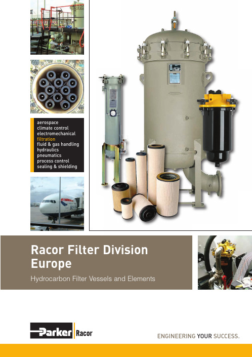
aerospaceclimate controlelectromechanicalRacor Filter Division Hydrocarbon Filter Vessels and ElementsParker Filtration’s global reputation as a reliablesupplier of superior filtration products is the result ForfurtherinformationEmail:*************************Plant expansionHydrocarbon FiltrationAutomotiveand Industrial Fuel FiltrationEngine Air Filtration SystemsMarine FiltrationCONTENTS6 – 78 – 1112 – 1314 – 1516 – 174 – 5Over 30 years of innovation, over 30 years of quality…Racor Fuelled UpHydrocarbonQualificationsFBO Filter ElementsRVFS SeriesElements2018 – 19Rre Filter Vessels1983196919851989199219951997200020021969It all began with a patented,and exceptionally efficient new way to remove water, dirt, rust and algae from diesel fuel.Diesel FuelTechnology1983Aquabloc ®filters debut, and RacorFilter/Separators make another significant leap in filtration efficiency.1985Racor becomes a division of ParkerHannifin Corporation, further strengthening one of the world’s most respected brands.GrowthQuality1989Racor earns Ford Q1 certification, the first ina series of quality awards from one of the world's leading engine and equipment manufacturers.Oil1992Every bit as vital and every bit as dirty asfuel.The Racor solution is an ingenious one, a cleanable oil filter that puts an end to frequent filter changes and disposal.CCV Products1995Racor starts cleaning up engine roomswith a crankcase ventilation system that keeps oily blow-by from damaging turbo chargers and other precision components.Racor Hydrocarbon1997Racor Hydrocarbon Filters and Vesselsdebut – offering customers flow rates to 1000 gpm and higher.UK Facility2000Having moved out of Morley into a purpose built factoryat nearby Dewsbury in 1998 Racor sees significant growth in Europe. 2000 saw the expansion of manufacturing capability to include all spin on series filters, and the establishment of a state-of -the-art design and test, research and development facility.High performance air filters2002Racor purchases Farr opening up opportunities in medium andheavy duty Engine Air applications.Industrial Filter Separator Vessels21Pressure Filter Vessel Summary2223More from ParkerRacorFuel Monitor VesselsIn Europe Morley, West Yorkshire in the UK becomes the centre of excellence in Europe.Fluid Condition MonitoringFrom the Refinery to the ForecourtOver the last 30 years Racor has become the premium name to trust in Marine and Automotive fuel filtration and water separation. With advanced fuel filtration laboratories in the USA and Europe and new ones planned for Asia and South America, with separate 2500GPM API/IP test facilities in the USA,Racor will continue leading the market in advanced fuel filtration technology It should therefore be of little surprise that Racor should utilise this breadth of experience in the fuel supply industry, producing Aviation Fuel API/IP 1581qualified water separators,1590 particulate filters and 1583 monitors, as well as Approved Vessels interchangeable products.From the refinery to the injector, at the terminal and on the forecourt, Racor has a solution to your fuel delivery needs.With engine tolerances getting tighter, whilstinjection pressures increase,the need for high quality conditioning designed to complement on-board RefineryAirportFiltration requirements will vary depending on local fuel quality.TerminalIndustrial & Marine Fuel ApplicationsPetrol ForecourtMulti-Product Pipeline Dedicated Pipeline Road Transport Refueler Dispenser Sea Cargo Aircraft Helicopter Fuel DrumsFuel StorageFloating JunctionUnderground Storagealso considered as direct supply.FMI Fuel Monitor elements will absorbchecks for aviation and diesel fuels.A quick 2 minute test will allow you toconsistent reliable and repeatable way than traditional clear and bright methods.The minimum filtration requirement of Jet-A/A1 into Airports and drum filling,is a filter (FWS) meeting the requirements of AP/IP1581 current addition.Injection molded nylon end capsassure tolerances equaled only inmachined parts. Nylon resinseliminate corrosion problems andoffer improved chemical andSymmetric layering of high efficiencyglass media into depth media caneliminate the need for metal center tubes– even in qualifying coalescer cartridges75 psi pressure requirements.Racor Division has been recognizedas the global leader in fuel filtrationapplications. Racor vessels, combined with Racorfilter elements, offer customers finer filtration,cleaner, drier hydrocarbonBy utilizing the latest computer-aided design tools, the engineering team takesspecific application requirements and quickly develops the necessary components to manufacture vessels and elements that meet industry codes and customer-specific requirements.Racor’s emphasis on advanced engineering is combined with a company-wide focus on uncompromising quality and premier customer service. This concentrated effort means that customers receive on-time delivery of the highest quality filtration systems available and that they meet the demanding requirements for performance and service life.C A R B O N F I L T E R E L E M E N T SGlass filled nylon end caps are standard,eliminating corrosion and offering excellent thermal stability and high impact resistance.Buna-N gaskets standard. Other options available.HIF corelessconfiguration.HIF ‘W’ petitor crossreferences.Synthetic Pleated Media Cartridges FS Series• 4 times the filtrationsurface area of comparable product available from competitors.•99.7% efficiency atstated element rating.•Designed and tested tomeet stringent requirements of API/IP 1590 Specifications and qualification procedures for aviation fuel microfilters. (Consult factory to obtain qualification test report).Micron ratings of 1 and 5 (approved) 10 and 25.HYDROCARBON FILTER ELEMENTSE L E M E N T SQualified to API/IP specification 1583.Qualification for Aviation Fuel Monitors with Absorbent Type Element.Separator Elementsstandard (Viton available on request)Multi-layered media for maximum solids holding –with absorbent media cross linked to trap and Works in the presence of fuel additives an surfactantsas specified in the API/IP Specification1583Interior and exterior media migration Micron ratings1, 5, 10 and 30.•Removes free andemulsified water to less than 5 PPM.•Water absorbingcapacity to four quarts depending upon cartridge size.•Progressive low flowrates or rapid differential pressure rise alert operators changeout is needed.•Spin-onfilters also Collapse pressureend caps are standard.Buna N gaskets standard.Recommended cartridgechangeout 20 PSID.cast filter head with four bolts. The slotted element change outs. With new element rotate into position on the locking ring The closure hardware consists of stainless steel nuts, bolts and washers with metal Maximum Flow Rates Prefilter 5-40 gpm 20Filter Sep 5-35 gpm 18Absorber5-25 gpm18Flow Range Diesel Jet Fuel Gasoline Delta P Delta PFBO-10Clean Dry ChangeFlow Range Diesel Jet Fuel Gasoline Delta P Delta PFBO-14Performance Specifications10FBO-60355 25FBO-6033551"Optional Accessories Automatic air eliminator Pressure relief valve Differential pressureLiquid level gaugewaterSupport stand ApplicationsFMI Monitor InstallationConnections• Inlet and Outlet:2 inch NPT•Main Drain and LiquidLevel Ports: 1/2 inch NPT•Vent and PressureRelief Connection: •Pressure Gauge/Sample Ports:1/8 inch NPT16, FS, and HIF coreless, high efficiency micronic series elements. Racor hydrocarbon filter housings are designed for removing solid contaminants such as dirt, rust, pipe Racor hydrocarbon vessels are designed for a single pass through the high efficiency element for clean • Inlet and Outlet: Style 1 – 3000# coupling Style 2 & 3 – 150# RF • Vent and relief valve: 3/4 inch NPT •Inlet and outlet permanently marked •Interior: epoxy-coated MIL–C–4556 E •Exterior: prime coated • Knife-edge cartridge mounting seals • Rod mount cartridge hardware• Stamped name plateOptional Accessories •Automatic air eliminator • Differential pressure gauge • Pressure relief valve • Manual drain valve •Sampling probesStyle 1Style 2Style 3Custom designs available. *Dimensions are reference only. For exact dimensions, request drawing for applicable model number.Dimensional Datain RVMF-60-1-148 5/8RVMF-120-1-288 5/8RVMF-200-1-448 5/8RVMF-40O-2-4414RVMF-600-3-4416RVMF-800-4-4418RVMF-1200-6-4420RVMF-2200-11-4428RVMF-3600-18-4436RVMF-520O-26-44421067A Model No.Features•Carbon steel construction; other materials available•10.34 bar ASME Code, Section VIII construction, stamped and certified •Yellow zinc-plated swing bolt closure •Buna-N o-ring cover seal •Hydraulic jack cover lift•Inlet and outlet permanently marked •Interior: epoxy-coated MIL-C-4556 E •Exterior: prime coated•Knife-edge cartridge mounting seals •Stamped name plate19INDUSTRIAL FILTER SEPARATOR VESSELSIndustrial Filter/Separator VesselsStandard Housing Data and Flow RatesMaximum Recommended Flow Rates At These ViscositiesModel No.1 CS 2.2 CS3 CS4 CS5 CS6 CS 8 CS 10 CS 31.0 SSU 33.0 SSU 36.0 SSU 39.0 SSU 42.3 SSU 45.5 SSU 52.0 SSU 58.8 SSU G PM LPM G PM LPM G PM LPM G PM LPM G PM LPM G PM LPM G PM LPM G PM LPM RVFS-222-122145 549115 43585 32265 24650 18940 15130 11425 95RVFS-244-233290 1098240 908180 681130 492100 37990 34160 22750 189RVFS-344-233435 1646340 1287250 946190 719150 568125 47390 34175 284RVFS-444-333580 2195480 1817360 1363260 984200 757180 681120 454100 379RVFS-456-436740 2801615 2328460 1741335 1268255 965230 871155 587130 492RVFS-656-5361100 4164915 3463675 2555500 1893385 1457335 1268230 871195 738RVFS-856-7361475 55831220 4618915 3463660 2498510 1930455 1722305 1154255 965RVFS-1056-9361850 70021530 57911150 4353830 3142640 2422570 2157380 1438320 1211RVFS-1256-11362220 84031835 69451375 5204995 3766765 2896685 2593455 1722380 1438RVFS-1456-13362585 97842140 81001605 60751160 4391895 3388800 3028530 2006445 1684RVFS-1656-15362955 111852445 92541835 69451325 50151020 3861915 3463610 2309510 1930RVFS-2056-19363695 139863060 115822295 86871655 62641275 48261140 4315760 2877635 2403RVFS-2456-23364435 167863670 138912755 104281990 75321530 57911370 5185915 3463765 2896RVFS-2856-27365175 195874280 162003215 121692320 87811785 67561600 60561065 4031895 3388Dimensional DataDimensional / Physical InformationModel No.Inlet/Outlet Flange Main Drain NPT A B C D Dry Weight Liquid Volume in. mm in. mm in.mm in. mm in. mm in. mm Lbs. Kgs.Gal. Ltr.RVFS-222-1222 51 1 2516 40652 1321 6 15217 432620 28135 132RVFS-244-233 3 76 1 2518 45777 1956 6 15223 584720 32760 227RVFS-344-2334 102 1 2520 50878 1981 6 15228 711850 38680 303RVFS-444-333 4 102 1 2524 61080 2032 6 15228 7111000 454115 435RVFS-456-436 6 152 1 2524 61097 24647.5 19136 9141100 499140 530RVFS-656-536 6 152 1.5 3828 711108 27437.5 19136 9141400 635200 757RVFS-856-7368 203 1.5 3832 813114 28969 22946 11681900 862270 1022RVFS-1056-9368 203 1.5 3836 914115 29219 22948 12192300 1043365 1382RVFS-1256-11368 203 1.5 3838 965116 29469 22948 12192500 1134415 1571RVFS-1456-133610 254 2 5142 1067118 299710 25454 13723400 1542530 2006RVFS-1656-153610 254 2 5148 1219120 304810 25460 15243800 1724580 2195RVFS-2056-193612 305 2 5154 1372125 317512 30569 17534500 2041900 3407RVFS-2456-233612 305 2 5160 1524129 327712 30571 18035700 25851160 4391RVFS-2856-273614 356 2 516616761433632143568020326500 29481390 5261Element OptionsCoalescer / Separator Element Selection Information NumberModel No.Coalescer .5 Mic. 1 Mic.2 Mic. 5 Mic. 25 Mic. Separator Silicone Treated Paper Element Quantity"32 Series""54 Series""55 Series" "58 Series" "78 Series" Element Quantity "05 Series"RVFS-222-1222CP-22632-TB CP-22654-TB CP-22655-TB CP-22658-TB CP-22678-TB 1SP-22605-S RVFS-244-2332CP-44632-TB CP-44654-TB CP-44655-TB CP-44658-TB CP-44678-TB 2SP-33605-S RVFS-344-2333CP-44632-TB CP-44654-TB CP-44655-TB CP-44658-TB CP-44678-TB 2SP-33605-S RVFS-444-3334CP-44632-TB CP-44654-TB CP-44655-TB CP-44658-TB CP-44678-TB 3SP-33605-S RVFS-456-4364CP-56632-TB CP-56654-TB CP-56655-TB CP-56658-TB CP-56678-TB 4SP-36605-S RVFS-656-5366CP-56632-TB CP-56654-TB CP-56655-TB CP-56658-TB CP-56678-TB 5SP-36605-S RVFS-856-7368CP-56632-TB CP-56654-TB CP-56655-TB CP-56658-TB CP-56678-TB 7SP-36605-S RVFS-1056-93610CP-56632-TB CP-56654-TB CP-56655-TB CP-56658-TB CP-56678-TB 9SP-36605-S RVFS-1256-113612CP-56632-TB CP-56654-TB CP-56655-TB CP-56658-TB CP-56678-TB 11SP-36605-S RVFS-1456-133614CP-56632-TB CP-56654-TB CP-56655-TB CP-56658-TB CP-56678-TB 13SP-36605-S RVFS-1656-153616CP-56632-TB CP-56654-TB CP-56655-TB CP-56658-TB CP-56678-TB 15SP-36605-S RVFS-2056-19320CP-56632-TB CP-56654-TB CP-56655-TB CP-56658-TB CP-56678-TB 19SP-36605-S RVFS-2456-233624CP-56632-TB CP-56654-TB CP-56655-TB CP-56658-TB CP-56678-TB 23SP-36605-S RVFS-2856-273628CP-56632-TBCP-56654-TBCP-56655-TBCP-56658-TBCP-56678-TB27SP-36605-Sequipped with FM 2” Series cartridges. The FMIaddition, they are not disarmed when surfactants and fuel additives are present.Features•Carbon steel construction; other material available F U E L M O N I T O R V E S S E L Sprocesses to meet industryFlow Rates Fuels Elements Inlet/OutletJet A, Jet A 1FS PleatedUp to 5,OOO gpm JP 4,5,8 FP Pleated NPT22Fluid Condition MonitoringF L U I D C O N D I T I O N M O N I T O R I N GApplications•Determination of particle size distribution forfilter testing.•Determination of water content in fuel.•Filter performance monitoring.•Pipeline commission trials.•Future development for telemetric analysis.Current practice in the aviation industry is to use a visual, ‘clear and bright’ test to make sure that the fuel being supplied from our refineries is free from solid matter and undissolved water at normal ambient temperatures.This test is subjective and cannot detect those contaminates that can really do damage to the engine and its critical tolerance fuel control components in todays modern aero engines.• Particle counting has been in lab environments since the 1960’s.• Recognised as an industry approved method.• Counts particulate distribution in hydraulic fluids.• Conforms with IS0/NASand SAE standards.• Lab performance in the field.• Small, portable and self powered data storage.• Dynamic 2 minute test procedure.• Simple operation.• Calibration to ISO standards (ISO 11171).• Particle counts per ml.• Sample particle distribution analysis.• Connects to exsisiting aviation sampling points.Parker Filtration’s global reputation as a reliable supplier of superiorSystemsFresh air. That’s whatIt’s easy to see whyParker Racor is themost trusted name inParker Racor fuel andoil filtration systemsParker WorldwideAE – UAE,DhabiTel: +971 4 8875600parker.me@AR – Argentina,Buenos AiresTel: +54 3327 44 4129AT – Austria,Wiener NeustadtTel: +43 (0)2622 23501-0parker.austria@AT – Eastern Europe,Wiener NeustadtTel: +43 (0)2622 23501 970parker.easteurope@AU – Australia,Castle HillTel: +61 (0)2-9634 7777AZ – Azerbaijan,BakuTel: +994 50 2233 458parker.azerbaijan@BE /LX – Belgium,NivellesTel: +32 (0)67 280 900parker.belgium@BR – Brazil,Cachoeirinha RSTel: +55 51 3470 9144BY – Belarus,MinskTel: +375 17 209 9399parker.belarus@CA – Canada,Milton, OntarioTel: +1 905 693 3000CH – Switzerland,EtoyTel: +41 (0) 21 821 02 30parker.switzerland@CN – China,ShanghaiTel: +86 21 5031 2525CZ – Czech Republic,KlecanyTel: +420 284 083 111parker.czechrepublic@DE – Germany,KaarstTel: +49 (0)2131 4016 0parker.germany@DK – Denmark,BallerupTel: +45 43 56 04 00parker.denmark@ES – Spain,MadridTel: +34 902 33 00 01parker.spain@FI – Finland,VantaaTel: +358 (0)20 753 2500parker.finland@FR – France,Contamine-s/ArveTel: +33 (0)4 50 25 80 25parker.france@©2008 Parker Hannifin Corporation. All rights reserved.RU – Russia,MoscowTel: +7 495 645-2156parker.russia@SE – Sweden,SpångaTel: +46 (0)8 59 79 50 00parker.sweden@SG – SingaporeTel: +65 6887 6300SL – Slovenia,Banska BystricaTel: +421 484 162 252parker.slovenia@SL – Slovenia,Novo MestoTel: +386 7 337 6650parker.slovenia@TH – Thailand,BangkokTel: +662 717 8140TR – Turkey,IstanbulTel: +90 216 4997081parker.turkey@TW – Taiwan,TaipeiTel: +886 2 2298 8987UA – Ukraine,KievTel +380 44 494 2731raine@UK – United Kingdom,WarwickTel: +44 (0)1926 317 878@US – USA,ClevelandTel: +1 216 896 3000VE – Venezuela,CaracasTel: +58 212 238 5422ZA – South Africa,Kempton ParkTel: +27 (0)11 961 0700parker.southafrica@European Product Information CentreFree phone: 00 800 27 27 5374(from AT, BE, CH, CZ, DE, DK, EE, EI,ES,FI, FR, IT, NL, NO, PL, RU, SE, SK,UK, ZA)GR – Greece,AthensTel: +30 210 933 6450parker.greece@HK – Hong KongTel: +852 2428 8008HU – Hungary,BudapestTel: +36 1 220 4155parker.hungary@IE – Ireland,DublinTel: +353 (0)1 466 6370parker.ireland@IN – India,MumbaiTel: +91 22 6513 7081-85IT – Italy,Corsico (MI)Tel: +39 02 45 19 21parker.italy@JP – Japan,FujisawaTel: +(81) 4 6635 3050KR – South Korea,SeoulTel: +82 2 559 0400KZ – Kazakhstan,AlmatyTel: +7 7272 505 800parker.easteurope@LV – Latvia,RigaTel: +371 745 2601tvia@MX – Mexico,ApodacaTel: +52 81 8156 6000MY – Malaysia,Subang JayaTel: +60 3 5638 1476NL – The Netherlands,OldenzaalTel: +31 (0)541 585 000parker.nl@NO – Norway,SkiTel: +47 64 91 10 00parker.norway@NZ – New Zealand,Mt WellingtonTel: +64 9 574 1744PL – Poland,WarsawTel: +48 (0)22 573 24 00parker.poland@PT – Portugal,Leca da PalmeiraTel: +351 22 999 7360parker.portugal@RO – Romania,BucharestTel: +40 21 252 1382parker.romania@Parker Hannifin (UK) LtdRacor Filter Division EuropeTel: +44 (0) 1924 487037Email: filtrationinfo@/rfdeCatalogue FDRB137GB1 10/2008Your local authorised Parker distributor。
Viresolve

Data Sheet BenefitsViresolve® Pro Solution:High-productivity Virus Filtration• Improved process economics with high mass capacity • High flux for faster processing• Consistent batch-to-batch performance• Easy to install, use and integrity test• Caustic sanitizable Viresolve® Pro Device:Robust Parvovirus Clearance• ≥ 4.0 log removal of parvovirus• Devices are 100% integrity tested with air/water diffusion and Binary Gas• Robust retention maintained during process interruption/depressurizationViresolve® Pro Solution Proven viral safety solution designed to provide the highest levels of retention assurance and productivityRobust. Productive. Proven.The Viresolve® Pro Solution provides a comprehensive, flexible template solution for virus filtration in biologics manufacturing. This proven viral clearance solution delivers the highest levels of retention assurance and processing efficiency across a broad range of feed streams.The Viresolve® Pro Solution is comprised of the innovative, high-performing Viresolve® Pro Devicein conjunction with the Viresolve® Pro Shield or the Viresolve® Pro Shield H prefilters. These products are designed to work togther to meet your needs providing high parvovirus retention, capacity and flux. Our industry-leading products and services, coupled with our viral clearance expertise, will help you successfully develop, implement, and validate theViresolve®Pro Solution.The life science business of Merck operates as MilliporeSigma in the U.S. and Canada.2Prefilters: Viresolve ® Pro Shield & Viresolve ® Pro Shield HProvides robust adsorptive (cation/mixed-mode) prefiltration to remove fouling protein aggregates • Enhance throughput and process robustness of Viresolve ® Pro Devices • Effective across a broad range of pH and conductivity conditionsEnhanced Process RobustnessFor feed streams with high levels of fouling proteinaggregates, the Viresolve ® Pro Shield or Viresolve ® Pro Shield H can be used to improve the capacity of the Viresolve ® Pro Device.These membrane prefilters adsorb protein aggregates that foul or plug the pores in the Viresolve ® Promembrane. Viresolve ® Pro Shield and Viresolve ® Pro Shield H have different membrane surface modifications to maximize adsorption of protein aggregates under a broad range pH and conductivity conditions (Figure 1).The Viresolve ® Pro Prefilter Selector Guide(TB1140EN00) provides guidance and information on prefilter selection.Virus Filter: Viresolve ® Pro DeviceProvides robust viral clearance• ≥ 4.0 logs of Minute Virus of Mice clearance • ≥ 5.0 logs of Murine Leukemia Virus clearance • Delivers high capacityHigh Virus RetentionRetention performance of the Viresolve ® Pro Micro 40 Devices, containing two lots of membrane, was evaluated under aggressive processing conditions. Testing was performed with a monoclonal antibody feed stream at 60 psi to a filtration endpoint of90% flow decay, followed by a 20 L/m 2 buffer flush. Samples were collected from final filtrate pools and a summary of calculated log reduction values (LRV) is shown in Figure 2. As can be seen from the results, the Viresolve ® Pro Solution achieved at least 5.8 logs of MVM retention. These results demonstrate robust virus clearance, even out to 90% flow decay, at high pressure.Virus retention performance of the Viresolve ® Pro Solution under a range of processing conditions is summarized in the application note Virus Retention Performance of Viresolve ® Pro Devices under a Range of Processing Conditions(WP3374EN).Figure 1.Contour plot showing the optimal pH and conductivity conditions for Viresolve ® Pro Shield and Viresolve ® Pro Shield H.654p HFigure 2.Summary of MVM results for two membrane lots of Viresolve Pro® Micro 40 Devices.0.01.02.03.04.05.06.07.08.0M V M F i n a l P o o l L R VLot 1Lot 2Building QualityThe virus retention performance and integrity of Viresolve® Pro Devices is assured with ourcomprehensive approach to quality.Assuring RetentionRetention performance is assured with our proprietary Binary Gas test which detects defects as small as 3-5 microns, that cannot be detected using a traditional air/ water diffusion test, Figure 3. This high sensitivity test is especially valuable for Viresolve® Pro Devices, where small defects could impact virus retention performance. Every Viresolve® Pro Device must pass Binary Gas testing before release, assuring the highest levels of virus retention for your filtration operations.End-UserIntegrityTesting andValidationMembrane& DeviceRelease TestsProcess& ProductValidationDevice 100%Integrity Tested inManufacturingIntegral Viresolve®Pro Membrane Non-Integral Viresolve® Pro MembraneSlow GasFast GasFigure 3.Principles of Binary Gas Test. This proprietary test measures the composition of a mixture of two gases on the upstream and downstream sides of the Viresolve® Pro membrane to detect defects as small as 3-5 microns in size.34High Capacity and FluxThe Viresolve ® Pro Solution efficiently processes feed streams of different pH, conductivities and proteinconcentrations. When used upstream of Viresolve ® Pro Devices, Viresolve ® Pro Shield and Shield H enhance the throughput and processing robustness of filtration operations.Figure 4 shows the results of throughput testing with Viresolve ® Pro Devices alone (A) or in conjunction with Viresolve ® Pro Shield and Shield H (B). In most cases, implementing the prefilter increased the capacity of the Viresolve ® Pro Device by an average of two-fold. The Viresolve ® Pro Solution enables rapid processing delivering mass flux in the 1.25-2.5 kg/m 2/hr range.768109543210M a s s C a p a c i t y (k g /m ) f o r ≤ 4-H o u r P r o c e s s T i m eFeed Protein Concentration (g/L)Figure 4A.Mass capacity on Viresolve ® Pro Devices with mAbs of different protein concentrations. In all cases, processing time was less than four hours.Figure 4B.Mass capacity of the Viresolve ® Pro Solution across a range of pH and conductivities. In all cases, processing was stopped at 75% flow decay or four hours.Shield H + DeviceShield + Device Device onlyV i r e s o l v e P r o V o r 4 h r s . (k g /m )Conductivity (mS/cm)3 6.5101620144545452013Flexible ManufacturingThe Viresolve® Pro Shield, Viresolve® Pro Shield H and Viresolve® Pro Devices are easily integrated into flexible, easy-to-use systems for pilot to full-scale manufacturing.Viresolve® Pro/Pro+ Magnus Holders for Viresolve® Pro SolutionViresolve® Magnus Holders are designed for large volume processing. The Viresolve® Pro Magnus Holder is designed to run the Viresolve® Pro Device alone, while the Viresolve® Pro+ Magnus Holder is designed to run the Viresolve® Pro Device coupled with either the Viresolve® Pro Shield or Shield H.• Quick and easy loading and unloading• No product contact• Minimized holder footprint with vertical orientation • Rods in multiple lengths for various sized installations • Simple manual hydraulics Mobius® FlexReady Solution for Virus FiltrationThe Mobius® FlexReady Solution for large-scalevirus filtration is an easy-to-use system featuring an optimized single-use flow path designed to fully support your virus filtration needs.For more information on the Mobius® FlexReady Solution for large scale virus filtration, refer todatasheet DS1259EN00.Viresolve® Pro+ Magnus Holder Viresolve® Pro Magnus Holder Mobius® FlexReady Solution5Partner with a leader in viral safetyVirus Filtration Process Development Service Optimizing a virus filtration process involves evaluatingthe effects of multiple process parameters to identify conditions that will ensure a robust, consistent, and economical operation. We work side-by-side with development engineers and manufacturers, helping them develop efficient, cost-effective filtration operations.We can help you:• Maximize filtration efficiency• Maximize process robustness• Meet your economic targets Viral Clearance ServicesViral clearance studies are critical to the validation of downstream processes, ensuring sufficient reductionof potential viral contaminants during downstream processing.BioReliance® viral clearance studies are designedand executed by experts in regulatory, downstream processing, and virology at our facilities in Singapore, the U.S., and the UK. Our global experts can support you with your IND and BLA studies in accordanceto regulatory guidelines for monoclonal antibodies, recombinant proteins, and plasma derivatives. Our dedicated project management support and local teams of experienced technical experts accelerate your time to results and minimize risk as you bring your product to market.Virus Filter Implementation ServiceOur engineers can leverage the results of bench-scale studies to help implement your pilot or production scale virus filtration operation. This streamlines implementation and avoids the pitfalls that can impactproduction timelines and process economics.6Nominal Dimensions and WeightsViresolve® Pro Shield, Viresolve® Pro Shield H, Viresolve® Pro Devices, and HoldersMicro 40Height: 4.03 cm (1.59 in.)Diameter: 4.37 cm (1.72 in.)3.4 cm2Empty: 14.73 gramsModus 1.1Length: 18.62 cm (7.33 in.)Width: 9.22 cm (3.63 in.)Height: 5.92 cm (2.33 in.)0.017 m2Empty: 0.37 Kg (0.8 lbs)Modus 1.2Length: 18.62 cm (7.33 in.)Width: 9.22 cm (3.63 in.)Height: 7.85 cm (3.09 in.)0.07 m2Empty: 0.63 Kg (1.4 lbs)Modus 1.3Length: 18.62 cm (7.33 in.)Width: 9.22 cm (3.63 in.)Height: 13.56 cm (5.34 in.)0.22 m2Empty: 1.39 Kg (3.1 lbs)Magnus 2.1Length: 34.30 cm (13.50 in.)Width: 20.96 cm (8.25 in.)Height: 4.42 cm (1.74 in.)0.51 m2Empty: 2.6 Kg (5.7 lbs)Full of water: 3.4 Kg (7.5 lbs)Magnus 2.2Length: 34.30 cm (13.50 in.)Width: 20.96 cm (8.25 in.)Height: 9.50 cm (3.74 in.)1.53 m2Empty: 5.8 Kg (12.8 lbs)Full of water: 8.3 Kg (18.3 lbs)Viresolve® Pro Magnus Holder (VPMH103000 / VPMH105000 / VPMH107000)Length: 78 cm (30.9 in.)Width: 76 cm (30 in.)Height: 127 cm (50 in.)Not Applicable141.5 Kg (312 lbs)Viresolve® Pro+ Magnus Holder (VPMH203000 / VPMH205000 / VPMH207000)Length: 104 cm (40.9 in.)Width: 76 cm (30 in.)Height: 127 cm (50 in.)Not Applicable186 Kg (410 lbs)Materials of ConstructionViresolve® Pro Shield, Viresolve® Pro Shield H, and Viresolve® Pro Devices, and HoldersMicro 40Polyethersulfone (PES)Bottom Endcap/Top Endcap: Polyvinylidene fluoride (PVDF)Not Applicable Modus 1.1,Modus 1.2,Modus 1.3,Magnus 2.1,Magnus 2.2Polyethersulfone (PES)Bottom Endcap/Top Endcap: Polyvinylidene fluoride (PVDF)SiliconeMicro 40Polyethersulfone (PES)Inlet Cap/Outlet Cap:Polypropylene/Polyethylene(copolymer)NotApplicableInlet and Vent: Female Luer-Lok™ FittingOutlet: Male Luer SlipModus 1.1, Modus 1.2, Modus 1.3Polyethersulfone (PES)Bottom Endcap/Top Endcap:Polyvinylidene fluoride (PVDF)Silicone Inlet and Outlet: 1.91 cm (.75 in.) sanitary fittingsIntegrated Vent: 0.32 cm (0.125 in.) with hose barbwith double O-ring sealMagnus 2.1, Magnus 2.2Polyethersulfone (PES)Bottom Endcap/Top Endcap:Polyvinylidene fluoride (PVDF)Silicone Inlet and Outlet: 3.81 cm (1.5 in.) sanitary fittingsVent: 1.90 cm (0.75 in.) sanitary fitting for the port* Fittings sold seperately7Materials of Construction (continued)Viresolve® Pro Shield, Viresolve® Pro Shield H and Viresolve® Pro Devices, and HoldersViresolve® Pro Magnus Holder Not Applicable Plates & Frames: 316 L stainless steel Not Applicable Not ApplicableClamp Rods: 300 series stainless steelFasteners, other components: 300 seriesstainless steelViresolve® Pro + Magnus Holder Not Applicable Plates & Frames: 316 L stainless steel Not Applicable Not Applicable Clamp Rods: 300 series stainless steelFasteners, other components: 300 seriesstainless steelFittings Kit Not Applicable Polyvinylidene fluoride (PVDF)Silicone Not Applicable SpecificationsViresolve® Pro Shield, Viresolve® Pro Shield H and Viresolve® Pro DevicesGood Manufacturing Practices These products are manufactured in a facility that adheres to the company QualityManagement System based on current industry standard regulations and practices, whichinclude Current Good Manufacturing Practices outlined in 00002011EX.ISO® 9001 Quality Standard These products are manufactured in a facility whose Quality Management System is approvedby an accredited registering body to the appropriate ISO® 9001 Quality Systems Standard. Particulate and Bioburden These products are manufactured in an ISO® Class 8 (Per ISO® 14644-1) controlledenvironment for particulate classification only.Animal Origin All components used in the manufacturing of these products are either animal-free or incompliance with EMEA/410/01.USP <87> Biological Reactivity Tests Component materials for these products were tested and meet the criteria for non-cytotoxicityfor the USP <87> Cytoxicity L929 MEM Elution Tests.USP <88> Biological Reactivity Tests Component materials for these products were tested and meet the criteria for USP <88>Biological Reactivity Tests for Class VI Plastics.Bacterial Endotoxin An aqueous extract from these products contains less than 0.25 EU/mL as determined by theLimulus Amebocyte Lysate (LAL) test.Membrane Bacteriophage Retention Membrane samples exhibited ≥ 4.0 LRV of φX 174 bacteriophage at a minimum challengelevel of 107 pfu/cm2 in the presence of a model protein at V75.Bacteriophage Retention Viresolve® Pro Device samples exhibited ≥ 4.0 LRV of φX 174 bacteriophage at a minimumchallenge level of 107 pfu/cm2 in the presence of a model protein at V75.Non-Fiber Releasing These products are non-fiber releasing filters as defined in 21 CFR 210.3(b)(6).Hydraulic Stress Test Samples were integral based on an Air/ Water Diffusion Test, before and after a forward stressto 4.1 bar (60 psid) at 25°C.Manufacturing Integrity Test All Viresolve® Pro Micro 40 Devices included in the Viresolve® Pro Micro 40 Device Kit mustpass the Binary Gas Test.All Viresolve® Pro Modus and Magnus Devices must pass the Pressure Hold, Water Flow Rate,Air/Water Diffusion Test and Binary Gas Test.All Viresolve® Pro Shield and Viresolve® Pro Shield H must pass an aerosol particle challengeand housing pressure hold.All Viresolve® Pro Devices exhibited an air diffusion flow rate at 3.4 bar (50 psig) in water at25 °C of less than or equal to:• 0.7 cc/min per Viresolve® Pro Modus 1.1 Device• 2.7 cc/min per Viresolve® Pro Modus 1.2 Device• 8.8 cc/min per Viresolve® Pro Modus 1.3 Device• 20 cc/min per Viresolve® Pro Magnus 2.1 Device• 60 cc/min per Viresolve® Pro Magnus 2.2 DeviceCaustic Sanitization These products may be sanitized by one 60-minute flush at 1.8 bar (25 psig) in 0.5 NormalSodium Hydroxide at 25 °C followed by a maximum 16-hour static soak.8Ordering InformationViresolve® Pro Magnus Holder For 1 to 3 Viresolve® Pro Devices1VPMH103000For 1 to 5 Viresolve® Pro Devices1VPMH105000For 1 to 7 Viresolve® Pro Devices1VPMHRD01071VPMH203000 Viresolve® Pro+ Magnus Holder For 1 to 3 Viresolve® Pro Devices and1 to 3 Viresolve® Pro Shields or Viresolve® Pro Shield H1VPMH205000For 1 to 5 Viresolve® Pro Devices and1 to 5 Viresolve® Pro Shields or Viresolve® Pro Shield H1VPMH207000For 1 to 7 Viresolve® Pro Devices and1 to 7 Viresolve® Pro Shields or Viresolve® Pro Shield HSplit clamp insert1VPMHINSERTRod handle1VPMHRDKN0B Rods For 1 to 3 Viresolve® Pro Devices2VPMHRD0103For 1 to 5 Viresolve® Pro Devices2VPMHRD0105For 1 to 7 Viresolve® Pro Devices2VPMHRD0107Viresolve® Pro and Pro+ Magnus Holder1VPMHADAPSK Fittings Kit (three 3.81 cm (1.5 in.) sanitaryfittings, two 3.81 cm (1.5 in.) blanks, one 1.27cm (.5 in.) vent fitting and one 1.27 cm (.5 in.)blank)3.81 cm (1.5 in.) Sanitary fittings For feed/permeate port6VPMHADAPSF3.81 cm (1.5 in.) Blanks For feed/permeate port6VPMHADAPSB1.27 cm (.5 in.) Vent fittings For vent port6VPMHADAPVF1.27 cm (.5 in.) Vent blanks For vent6VPMHADAPVB Hydraulic pump1MP0DHYPUMP Pressure gauge1MP0DHYGAGE Hydraulic fluid (1 liter)1MP0DHFLUID9Lit. No. DS0006EN00 Ver. 12.02019-2540801/2020Ordering Information (continued)© 2020 Merck KGaA, Darmstadt, Germany and/or its affiliates. All Rights Reserved. Merck, the vibrant M, Millipore, Flexware, Mobius, and Viresolve are trademarks of Merck KGaA, Darmstadt, Germany or its affiliates. All other trademarks are the property of their respective owners. Detailed information on trademarks is available via publicly accessible resources.To place an order or receive technical assistancePlease visit /contactPSFor additional information, please visit Merck KGaAFrankfurter Strasse 250 64293 Darmstadt, Germany。
压缩空气过滤器系列说明说明书

CompressedAir FiltrationCompressed Air Filtration Filters | Coalescers | Absorbers | Elements | Mist EliminatorsIn any compressed air net distribution it is a must to install one or more filters. As a result, an improved air quality is achieved, which benefits your complete compressed Using only a single filter could result in saturation of the reduced air quality or end upprematurely replacing your elements.TECHNOLOGY YOU CAN TRUSTA V A I LAB I L I T Y S E R VI C E AB IL I T Y R E L I A B I L I T YP A R T N ER SH IPS I MP L I C I T YUser BenefitsBoost quality and productivity • Purify the compressed air by eliminating oil/dust contaminants • Higher final product quality• Increase your overall productivity Save costs• Prolong the life span of your operation process (machine/equipment...)• Reduce potential downtime• Annual service intervals to ensure optimal operations Easy operation and installation Compatible with any compressor technology• Can be installed quickly and into an existing network• Optional pressure drop device (indicator/gauge) to advise on the cartridge replacement• Cartridge replacement done in no time• No electrical supply neededRisks You AvoidImpurities in the compressed air can cause:• Damage to the distribution lines, increasing the leakage risk • A considerable increase in maintenance costs• A reduction in the efficiency and life span of the pneumatic devices • Deterioration of the final product quality• Limitations to the reliability of the production process and all its components• Decrease of the overall profitabilityQuincy Filters Keep Your Air Distribution Network In Optimal Shape!2Important GuidelinesWhen selecting purification equipment for your compressed air system, these are some useful guidelines to consider:1. Depending on the application, each point of use in the system may require a different compressed air quality.2. Ensure that the purification equipment which is being chosen will provide the required air purity in accordance with the classi-fications from the ISO 8573-1:2010 table.3. When comparing filters to one another, make sure they have been tested in accordance with the standards of ISO 8573 and ISO 12500 series.4. Whenever you compare different filtration solutions, it is crucial to keep in mind that the filter performance is highly dependent on the inlet conditions.5. When taking into account the operational cost of oil coalescence filters, only compare the initial saturated wet pressure loss. The reason for this is that dry pressure loss is not representative forperformance in a normally wet compressed air system.36. For dust filters on the other hand, one can expect the pressure drop to rise over time. A low starting pressure drop does not mean it will remain as such throughout the filter element’s lifetime.7. Consider the total cost of ownership for purification equipment (purchase, operational and maintenance costs).Your local sales representative can help you to select the optimal purifcation equipment for your compressed air system.Compressed Air According to ISO 8573-1:2010Depending on the customer’s application, a certain air purity is required. These purity requirements have been categorized in air purity classes. The purity classes are defined in the ISO 8573-1 standard, edition 2010.This table defines 7 purity classes ranging from 0 up to 6 following the rule: the lowr the class, the higher the air quality.Model Grades 1800-10,500A Solution for Every Air QualityReference condition: pressure 7 bar (102 PSI). Maximum operating temperature of 122°F, only for QAF series.Minimum operating temperature of -4°F4Model Grades 6-1500Filter Range OverviewThe quality of air required throughout a typical compressed airsystem varies. Offering an extensive filter range, Quincy Compressor can always match your precise requirements, ensuring that all types of contamination are avoided and costs are reduced to an absolute minimum.QMF Filter RangeMicronic coalescing filters for general purposeprotection, removing solid particles, liquid water and oil aerosol.Total Mass Efficiency: 99 %QPF Filter RangeParticulate filters for dust protection. Removes solid particles, dust, liquid and oil aerosol.Count Efficiency: 99.8% at MPPS (MPPS = 0.1 micron)QCF Filter RangeHigh-efficiency coalescing filters, removing solid particles, liquid water and oil aerosol.Total Mass Efficiency: 99.9 %QAF Filter RangeActivated carbon filter for removal of oil vapour and hydrocarbon odors.1000 Hour Lifetime* Inlet oil concentration = 40 mg/m3** MPPS = Most Penetrating Particle Size of 0.01 µm5High Temperatures1 Micron Dust Filters, 450°F, 150 PSIG• Designed specifically for Heat Reactivated Desiccant Air Dryers • Nomex outer layer is provided for high-temperature operation • Push-to-fit design used on threaded filters for easy filter element replacement•Multiwrap element construction provides optimum performanceAluminum Housing Threaded NPT Connctions 15 to 650 CFM, Series HTDT• Features a high-temperature dust filter with heavy-duty bowl • Ribbed bowl facilitates removal when changing elements NOTE: Alloy filters shipped loose will have a special high-temperature black powder coat paint.ModelsHTDT 15 & 30Models HTDT 65–650Specifications & Engineering Datasponding to the working pressure.6Mechanical Moisture Separators6 to 1500 CFM, 232 PSIG, Series QWSQuincy Mechanical Moisture Separators are designed to removebulk liquids and large volumes of water. They are typically installeddownstream of after coolers, air receivers, refrigerated air dryers andat strategic points of use throughout the compressed air distributionsystem. The design employs an internal spinner to create a centrifugalaction that effectively removes large quantities of water.• Aluminum housings (1⁄4” to 3 NPT) to prevent corrosion• Low pressure drop: < 1 PSIG• CRN approvedSpecifications & Engineering Data7Stainless Steel FiltersCoalescer — AbsorberQuincy’s line of 316 grade Stainless Steel filters for pressure requirements of 750 PSIG through 5000 PSIG feature:• Three pressure ranges (750 PSIG, 1,500 PSIG, 5,000 PSIG)• Heavy-duty, Stainless Steel tie rod design for 1500 PSIG and 5000 PSIG750 PSIG/250°F 60 to 2000 SCFM (1/2” to 2” NPT)• SSCT standard coalescer • SPCT polishing coalescer • SACT activated carbon1500 PSIG/250°F 65 to 2050 SCFM (1/2” to 2” NPT)• ESCT standard coalescer • EPCT polishing coalescer • EACT activated carbon5000 PSIG/250°F 28 to 775 SCFM (1/2” to 11/2” NPT)• VSCT standard coalescer • VPCT polishing coalescer • VACT activated carbonHigh-PressureAluminum FiltersCoalescer — AbsorberQuincy’s aluminum alloy, 750 PSIG high-pressure filter lineup offers an economic alternative to the high cost of stainless steel. There are two levels of coalescing and an activated carbon absorber. Ideally suited for the PET bottle blowing industry, the coalescers remove various levels of liquid aerosols and the activated carbon absorber removes vapor and odors.• High-temperature capacity (250°F.)• Multiwrap element construction for optimum performance and long life• Synthetic lubricant and mineral oil compatibility• Large sump and quiet zone to prevent re-entrainment • Push-to-fit design for easy filter element replacement• Modular design allows for easy installation of multiple filters and saves energy750 PSIG/250°F 150 to 3000 SCFM (1/2” to 2” NPT)• HSCT standard coalescer • HPCT polishing coalescer • HACT activated carbon750 PSIG - Specifications & Engineering Data8corresponding to the working pressure.corresponding to the working pressure.9High-Pressure1500 & 5000 PSIG - Specifications & Engineering Data10corresponding to the working pressure.corresponding to the working pressure.11Models E_T 65-2050V_T 28-775Models H_T 94 & 147Models S_T 60–2000ModelsH_T 265–1882Unique Double Element Design1,500 cfm through 15,000 cfm models utilize a space-saving double element design (see Figure 2). Using a double nesting technique, the Quincy Mist Eliminator offers high efficiency separation in a low profile package. By nesting an element inside an element, total surface area is greater than conventional single element designs. Due to reduced overall height, the Quincy Mist Eliminator can be installed in locations where conventional single element designs cannot. For example, a 10,000 cfm Quincy Mist Eliminator low profile design is only 118 inches tall. Compare this to other single element designs that are 210 inches tall. That’s a reduction of over 7 feet in overall height! Imagine the savings in time and convenience when you change the element or service the unit.All Quincy Mist Eliminator tanks are ASME coded and stamped. Standard equipment includes a calibrated differential pressure gauge and enamel paint. No Loss Demand Drains are optional. Pressure relief valves are not included but may be required by local codes.Mist EliminatorHigh Efficiency Heavy-Duty Coalescing FilterLong Life and Low Pressure DropThe Quincy Mist Eliminator is a heavy-duty coalescing type filter engineered to efficiently remove oil, particulate, and water from compressed air. By using a combination of impaction, interception and Brownian Movement, the Quincy Mist Eliminator achieves100% efficiency in removing particles 3 micron and larger, 99.8% of 0.1 micron and larger and 99.5% of 0.01 micron and larger. Typical pressure drop is less than 1 psig. Average element life in continuous service is 10 years. A 10-year element life can be achieved in relatively clean environments.• Lower pressure drop compared to conventional coalescing and particulate filters (average 1 psig versus 6 psig). Higher pressure drops require the compressor to operate at an elevated pressure, therefore requiring more power. Every 2 psig reduction in pres-sure saves approximately 1% air compressor power based on 100 psig operating pressure. Quincy Mist Eliminator could easily save in excess of $1,500 per year in air compressor electrical energy (based on 8,000 hours per year operation, $0.07 per Kw hour, 100 hp compressor and a 93% motor efficiency).• Large tank volume captures and retains inadvertent lubricant discharge caused by compressor separation system malfunction, which protects downstream equipment.• Average element life of 10 years versus 6 months for conventional coalescing and particulate filter elements reduces maintenance and waste disposal.12Mist EliminatorSpecifications & Engineering DataNotes: Larger Sizes Available, Consult Factory * Does Not Include Rigging.13Quincy Helps Y ou Do More. For Less.Combining nearly 100 years of expertise with unrivaled quality and performance, Quincy Compressor is the headquarters for your air filtration needs. Innovative filtration solutions are engineered to provide the best quality air and meet today’s increasing quality demands. Backed by the Air Quality Performance Guarantee, Quincy Compressor offers a full line-up of superior quality filtration solutions to meet the high quality requirements of your specific application. Exceed your expectations by providing your system with Quincy Compressor filters. Compressed Air FiltersQuincy Compressor Air Quality Performance Guarantee• Quincy Compressor offers a performance guarantee on its Air Treatment Filtration line. Quincy’s Filters are guaranteed to perform to the currently published specifications as found in filtration documentation available at /literature_ library.html.• Under normal operating conditions, and when installed in an original installation, the Quincy QCF, QMF, and QPF filter elements meet or exceed air quality standards of ISO 8573. The Quincy filters are guaranteed to operate for 8,000 hours or 12 months, which-ever shall occur first, before reaching the recommended 6 PSIG pressure differential for filter replacement.• Quincy Compressor guarantees that the aforementioned filters will perform as stated above, or Quincy Compressor will either repair or replace the filter or element, at Quincy’s discretion. Quincy Compressor will not be responsible for removal, reinstallation and/or related costs.The Air Quality Performance Guarantee is in accordance and established based upon Air Quality-ISO 8573 standard for oil-free and contaminant-free compressed air applications. The Air Quality Performance Guarantee remains in effect for the below listed site so far as all installation and maintenance requirements set forth and in accordance with the warranty and policies and procedures handbook, under Section 1 General Information; Warranty Coverage Rules are maintained.1415Quality Comes in All Shapes and Sizes—But Just One Color.The Quincy PromiseQuincy Compressor and its partnering distributors promise to provide you with uncompromising reliability in all Quincy equipment. This makes your compressed air system one less thing that you need to worry about, allowing you to focus on your company’s productivity and profitability.The Quincy SolutionOperating at peak efficiency and providing quality product is a priority for many of our customers. Quincy Compressor in partnership with our global network of authorized distributors strives to be your provider for all of your compressed air system needs. From the air compressor to filtration to dryers and storage solutions, Quincy Compressor is your single-source provider for all of your compressed air system needs.Air CompressorsQuincy Compressor is a premier provider of many different types of air compressors designed for a variety of applications using different compression technologies.The Quincy QT is a Reciprocating Splash Lubricated compressor for tough everyday use. The Quincy QP is a reciprocating fully pressure lubricated compressor for a competitive advantage. The Quincy QR is a reciprocating compressor designed for the most demanding conditions. The Quincy QGS 5-30 HP is a heavy-duty belt drivenrotary compressor at a competitive price. The Quincy QSI provides an industrial-grade premium fixed-speed rotary screw air compressor.The Quincy QGV provides a premium variable-speed rotary screw air compressor designed to optimize your energy efficiency. Compressed Air TreatmentQuincy Compressor is your single-source provider of compressed air treatment products to complement your air compressor. Quincy provides refrigerated air dryers, desiccant air dryers, compressed air filtration from 5 to .01 micron, condensate drains, condensate management systems, storage solutions, and flow control valves. Quincy Compressor is truly a single-source provider for all of your compressed air needs.Genuine PartsGenuine Parts from Quincy Compressor keep your equipmentrunning like new. When servicing your Quincy compressor, insist on Genuine Quincy parts. Not only will you save time and money, but you will gain the peace-of-mind from using only the highest quality parts worthy of the Quincy name.System ControlsWhether you have one air compressor or many air compressors from many different manufacturers, Quincy Compressor provides you with a way to control and monitor all of the components in your compressed air system in a way that maximizes your energy efficiency and decreases your energy costs. Whether you need to control your system on site or from half way around the world,Quincy Compressor is your source for reliable, efficient controls.©2017 Quincy Compressor. All rights reserved. Printed in U.S.A.(QATF-005 10/19)701 N. Dobson Avenue | Bay Minette, AL 36507Phone 251.937.5900 | Fax 251.937.0872Email:*************************|。
- 1、下载文档前请自行甄别文档内容的完整性,平台不提供额外的编辑、内容补充、找答案等附加服务。
- 2、"仅部分预览"的文档,不可在线预览部分如存在完整性等问题,可反馈申请退款(可完整预览的文档不适用该条件!)。
- 3、如文档侵犯您的权益,请联系客服反馈,我们会尽快为您处理(人工客服工作时间:9:00-18:30)。
Improved Filtration Performance of Continuous Alumina-fiber-reinforced Mullite Composites for Hot-Gas CleaningSatoshi Kitaoka w and Naoki KawashimaJapan Fine Ceramics Center,Nagoya 456-8587,JapanYoshinobu KomatsubaraMitsui Mining Material Co.,Omuta 836-0062,JapanAkira YamaguchiNagoya Institute of Technology,Nagoya 466-8555,JapanHisao SuzukiShizuoka University,Hamamatsu 432-8561,JapanThe effect of filtration layer morphology on filtration perform-ance at 673K was investigated for continuous alumina-fiber-reinforced mullite composite filters that capture fly ash on their outer surfaces.Two types of filtration layers were prepared on the outer surfaces:a mono-layer consisting of mullite agglom-erated particulates and a bi-layer,with mullite whiskers formed by a vapor-phase reaction and strongly adhered to the particu-lates exposed on the outer surfaces.For filters with mono-fil-tration layers,the filtration efficiency was improved slightly by increasing the filtration layer thickness.However,the maximum differential pressure increased during the filtration tests.Adhe-sion of whiskers to the outer surface decreased the maximum differential pressure to about one-third less than that with the mono-filtration layer.This low differential pressure remained constant throughout the duration of the test,with corresponding increases in filtration efficiency.I.IntroductionHOT -GAS particulate filters are key components for advanced coal-based power generation systems such as pressurized fluidized-bed combustion (PFBC)and integrated coal gasifica-tion combined cycle (IGCC).Filters should allow easy removal of dust cakes accumulated on the filter surfaces and excellent reversibility of the differential pressure during pulse cleaning.For this reason,adhesion of the dust cakes to the filters should be suppressed as far as possible.Adhesion is generally related to the formation of alkali-containing liquids in the cake and chem-ical reactions between the filter element and the fly ash.1Chem-ical reactions have a particularly strong effect on dust adhesion and make pulse cleaning difficult.To simplify the study of the interaction of fly ash with filters,we have considered a repre-sentative ash containing SiO 2and Al 2O 3(the principal constit-uents)and K 2O (one of the most reactive constituents,whichsignificantly affects the nature of the ash at high temperatures).As the SiO 2–Al 2O 3–K 2O phase diagram indicates,2mullite is one of the equilibrium phases that can form from ashes of simple composition (e.g.,SiO 2:Al 2O 3:K 2O 571:28:1wt%for Ash No.10,distributed by the Association of Powder Proc-ess Industry and Engineering,Japan;SiO 2:Al 2O 3:K 2O 563.8:35.8:0.4wt%for the fly ash that was collected from a hop-per at the PFBC demonstration plant z ).The phase diagram indicates that Al 2O 3reacts with fly ash 3and,therefore,direct contact should be avoided.Because of the poor thermal conductivity of unreinforced ce-ramic filters,however,large temperature gradients form between the inner and outer surfaces of the filters during excessive gas cleaning,or as the result of sudden ignition of char accumulated on the filtration surfaces or from a combination of the two rea-sons.Thermal stresses induced by the temperature gradient lead to catastrophic failure of the filters,4,5resulting in low reliability.To be used successfully,these filters require precise control of operating conditions and constant observation.Continuous-fiber-reinforced filters are expected to show ex-cellent damage tolerance,durability,and reliability.Oxide ma-terials are inherently stable in oxidizing environments such as the PFBC system and have more corrosion resistance to alkali species than the non-oxides SiC and Si 3N 4.6Because of the poor sinterability of mullite,if this material is used as the matrix of the fiber-reinforced filter,the composite must be sintered at high temperatures to increase the bonding strength among the mullite grains.Unfortunately,mullite fibers stable at high temperatures have not yet been produced,so that only high-purity a -Al 2O 3fiber (which has the highest thermal stability,1673K,of any oxide fiber)is available.However,if the Al 2O 3fibers are exposed on the filtration surfaces,the fibers react with the ash cakes,leading to an increased differential pressure of the filters.There-fore,the filtration surfaces of the filters should be fully covered with mullite.We have developed cylindrical composite filters that capture fly ash on their outer surfaces.3The filters consist of a mullite filtration layer and a substrate layer of continuous Al 2O 3-fiber-reinforced mullite matrix composite.The filters were fabricated by dipping a two-dimensional woven sheet of the fibers into a slurry that had been prepared from large mullite particles and an alkoxide-derived mullite precursor solution.The precursor coat-ed onto the large mullite particles formed very fine mullite45J ournalJ.Am.Ceram.Soc.,88[1]45–50(2005)DOI:10.1111/j.1551-2916.2004.00027.xRalf Riedel—contributing editorThis research was supported in part by the Center for Coal Utilization,Japan (CCUJ),under the Next-Generation Coal Utilization Technology Development Study (Environ-mentally Friendly Coal Combustion Technology),promoted by the New Energy and In-dustrial Technology Development Organization (NEDO),under contract from the Ministry of Economy,Trade,and Industry (METI).It has also been supported by Japan Coal Energy Center (JCOAL),under a contract from METI,as a part of regional R&D consortium projects.wAuthor to whom correspondence should be addressed.e-mail:kitaoka@jfcc.or.jpManuscript No.10492.Received August 28,2003;approved July 20,2004.zWakamatsu Pressurized Fluidized-Bed Combustion combined cycle demonstration plant of the Electric Power Development Co.,Japan.particulates during heating.These particulates accelerated the neck growth between the large particles,even at low tempera-tures.Therefore,the precursor allowed the sintering of large mullite particles without Al2O3fiber damage,resulting in in-creasedflexural strength for the composites while inhibiting de-lamination of the wovenfiber sheets.Although the morphology of thefiltration layers strongly af-fectsfiltration behavior,there is limited information on the op-timal morphology for improvingfiltration performance.In particular,if a layer consisting of particles with large aspect ra-tios,such as whiskers,is formed on thefilter surfaces,it can be expected to have a small open pore size and large open porosity, resulting in a decreased differential pressure and more efficient dust removal.In this case,the particles need to be stronglyfixed to thefilter surfaces to prevent them from falling out as a result of shock during gas cleaning.For the present study,the effect offiltration layer morphol-ogy on the performance of continuous Al2O3-fiber-reinforced mullite composites was investigated.Two types offiltration lay-ers were produced on thefiber-reinforced composites:a mono-layer consisting of mullite particulates and a bi-layer with mul-lite whiskers formed by vapor-phase reaction and strongly ad-hered to mullite particulates exposed on the outer surfaces.II.Experimental Procedure(1)MaterialsThe mullite precursor coated onto the large mullite particles ac-celerated sintering of the large particles,resulting in a lower sin-tering temperature without degradation of the Al2O3fibers.3 The precursor solution was prepared by a polymeric sol–gel process from aluminum and silicon alkoxides as follows:7First, tetraethoxysilane(TEOS)was added to dehydrated ethanol (TEOS concentration of10mol/m3).Distilled water and hydro-chloric acid were then dropped into the solution in molar ratios of2and0.1,respectively.The TEOS was partially hydroly-zed by reflux at343K for50h,producing what is hereafter called the silicon precursor.Next,aluminum isopropoxide (Al(OCH(CH3)2)3)at a concentration of10mol/m3was dis-solved in2-methyl-1-propanol at room temperature and ref-luxed at368K for24h.The solution obtained is referred to hereafter as the aluminum precursor.A mullite precursor solu-tion was synthesized by mixing the silicon precursor with the aluminum precursor(Al/Si molar ratio53)and stirring at room temperature for5h.The chemical copolymerization of partially hydrolyzed species resulted in high compositional homogeneity of the precursor solution.A slurry was prepared from the mullite precursor solution and mullite particles(KM101,mean diameter0.75m m;KCM Co.,Nagoya,Japan).The concentration of the mullite particles was25wt%.A two-dimensional woven sheet of a-Al2O3fibers (ALMAX,Al2O3purity of99.5wt%,mean diameter10m m; Mitsui Mining Material Co.,Tokyo,Japan)was vacuum infil-trated with the slurry.The infiltrated sheet was wound around an Al2O3cylindrical mold and then dried during rotation at100 rpm to prevent gravity segregation of the slurry in the sheet.The centrifugal force induced by the rotation moved part of the in-filtrated slurry to the outer surface of the sheet,resulting in the buildup of a mullite layer on the outer surface.Next,the sheet with the mold was sintered at1673K in air for2h.The cylin-drical composite obtained(outer diameter55mm,thickness 2.5mm,width150mm)is hereafter referred to as sample A.The thickness of the mullite layer on the outer surface of sample A was B5–10m m,which acted as afiltration layer.Thefiber frac-tion of the supporting layer was B30vol%.In case of dustfiltration at the exterior wall of the cylindrical composite,a decrease in pore size from the interior of the cyl-inder to its exterior,as well as a uniform size distribution of the exterior pores,was necessary for easy removal of the cake dur-ing back blowing.To achieve this,two types offilters were pro-duced using sample A as a substrate layer.For onefilter,a slurry consisting of15wt%mullite particles and the precursor solutionwas sprayed onto the outer surface of sample A,and thefilterwas sintered again at1673K,in air,for1h.Thisfilter is referredto as sample B.Anotherfilter was prepared by adhering mullite whiskersonto the outer surface of sample A by a vapor-phase reaction.This whisker-synthesizing method has been referred to in previ-ous studies.8,9First,TEOS and aluminum nitrate enneahydrateAl(NO3)3Á9H2O were dissolved in dehydrated ethanol.AlF3 powders then were added to the solution and fully mixed in.Theamount of AlF3was2wt%of the Al(NO3)3Á9H2O,and the Al/ Si molar ratio of the mixture was3.An ammonia solution wasadded to the mixture and precipitates were produced.The pre-cipitates were dried at573K for24h.A slurry consisting of thedried powder(15wt%),polyvinyl butyral(1wt%),and dehy-drated ethanol was prepared.The slurry was applied liberally to the outer surface of the sample,and the coated sample then was dried at room temperature.The cylindrical composite was placed in an airtight container andfired at1473K for2h.After firing,the surplus mullite whiskers that had formed on the outer surface were removed by ultrasonic washing in water. The edges of the remaining whiskers were strongly adhered to the mullite particles exposed on the outer surface,which was fully covered by the whiskers.Thisfilter is referred to as sample C.When the adhesion of the whiskers to the top surface was achieved at higher temperatures and for longer times than those for sample C,the whiskers on the surface grew,and neighboring whiskers combined,resulting in the formation of plate-like particles.(2)Measurement and AnalysisThefiltration surfaces and cross sections of thefilters were ob-served by scanning electron microscopy(SEM).For sample C, mullite whiskers on the surface were examined by transmission electron microscopy(TEM).Chemical analysis,with a spatial resolution of B10nm,was performed by energy-dispersive X-ray spectroscopy(EDS)and electron diffraction(ED).The po-rosity and distribution of the pores in the composite were meas-ured by mercury intrusion porosimetry.The permeability,k,of thefilters was determined from the relationship between theflow rate and the applied N2pressure, according to Darcy’s law,k¼Lu mD Pð1Þwhere D P is the differential pressure across afilter of thickness L.The superficial velocity,u,of the gas with viscosity,m,is as-sumed to be the same throughout thefilter.Thefiltration performance of the samples was evaluated us-ing an apparatus(Hosokawa Micron Corp.,Osaka,Japan)in accordance with the German VDI/DIN standard3926.10The cylindrical composites were cut into100-mm lengths,and both bases of the cylindrical samples were sealed by the holders in the apparatus.Dust-containing air was sucked inward through the samples,and the dust cakes that accumulated on the outer sur-faces were removed by cyclically blowing air outward.The dif-ferential pressure across the samples was monitored during the filtration tests.A sample offly ash,which was collected from a hopper at the PFBC demonstration plant,was used as the dust for thefiltration tests.Figure1shows the particle size distribu-tion of the dust,which has two peaks.The average diameter of the dust particles was7.4m m.Figure2shows an SEM micro-graph of the dust.Spherical particles,which were probably formed by solidification of melted dust,and agglomerated par-ticles were observed.Thefiltration performance using this dust was evaluated at673K,the upper-limit temperature of the ap-paratus,for a dust concentration of5g/m3,afiltration velocity of0.097m/s,a pulse blowing pressure of0.2MPa,a blowing interval of150s,and a total number of204blowing cycles. These tests were conducted as a preliminary assessment of the46Journal of the American Ceramic Society—Kitaoka et al.Vol.88,No.1performance of the filters,which in practice would be used at temperatures 41100K.The dust passing through the filter samples was captured with filter paper.The average dust con-centration in the clean gas after filtration was determined by di-viding the mass of the captured dust by the total amount (5.1m 3)of clean gas that passed through the filter paper.The filtra-tion efficiency,Z ,was calculated as follows:Z %ðÞ¼1ÀC =C i ðÞÂ100ð2Þwhere C i and C are the dust concentrations before and after fil-tration,respectively.III.Results and DiscussionFigure 3shows SEM micrographs of typical cross-sections and filtration layer surfaces of the samples.For sample A,the outer surface was covered with mullite particulates that had accumu-lated on the Al 2O 3fiber sheets.The thickness of the particulate layer was B 5–10m m.This layer consisted of agglomerated mul-lite particles with many pores (less than a few micrometers)among the agglomerates and acted as the filtration layer.Al-though regions among the fiber bundles were filled with the mullite particulates,there were many pores in the bundles.As shown in Fig.3,large gaps were observed among the bundles and agglomerated particulates.For sample B,the mullite par-ticulate layer,which was 20–30-m m thick,acted as the filtration layer.The filtration surface seemed less uneven,and the pores smaller,among the agglomerates of sample B than in sample A.In sample C,the whiskers were arranged on the particulate layer perpendicular to the outer surface.The thickness of the whisker layer was the same as the length (B 4m m)of the whiskers.The aspect ratio (length/width)of the whiskers was B 15.The filtra-tion surface of sample C was fully covered with whiskers.There were no large depressions,such as those of sample A,and the pores observed on the surface of sample C seemed to be smaller than those of the other samples.Incidentally,the microstructure of the substrate layer of sample C was the same as those of the other samples.The ED pattern of a single whisker corresponded to that of a single crystal of mullite.TEM–EDS analysis of the whiskers indicated an average Si/Al molar ratio of 0.34,similar to the stoichiometric composition (0.33)of mullite.No deteri-orated layers were observed at the interfaces between the mullite whiskers and the mullite particulate layers that had accumulated on the Al 2O 3fiber sheets.We propose a mechanism for the formation of whiskers per-pendicular to the outer surface based on thermodynamic argu-ments.Figure 4shows the equilibrium partial pressures of the gaseous species and stable regions of the condensed phases un-der a constant F (g)partial pressure of 1.3Â10À8Pa,calculated from the decomposition reaction of AlF 3(s)(AlF 3(s)-Al (1)13F (g))as a function of O 2partial pressures at 1473K for the Al–O–F–Si system.As shown in Fig.4,when AlF 3(s)particu-lates exist on the outer surface of the cylindrical composites,the AlF 3(s)reacts with oxygen to mainly produce AlOF 2(g)as follows:AlF 3ðs Þþ1=2O 2ðg Þ!AlOF 2ðg ÞþF ðg Þð3ÞConsequently,an oxygen potential gradient forms on the outer surface.Under O 2partial pressures of o 3.2Â10À24Pa,the partial pressure of AlF (g)is the highest of all the gaseous species in the system.The partial decomposition reaction of AlF 3(s)can be represented as follows:AlF 3ðs Þ!AlF ðg Þþ2F ðg Þð4ÞFor O 2partial pressures of 43.2Â10À24Pa,the partial pressure of the AlF decreases,and the AlF condenses into Al 2O 3.AlF ðg Þþ3=4O 2ðg Þ!1=2Al 2O 3ðs Þþ3F ðg Þð5ÞUnder O 2partial pressures of o 9.6Â10À19Pa,silicon species in the vicinity of the AlF 3(s)particulates change to Si (s),accompa-nied mostly by the production of SiF 4(g).When O 2partial pres-sures are 49.6Â10À19Pa,SiF 4(g)condenses into SiO 2as follows:SiF 4ðg ÞþO 2ðg Þ!SiO 2ðs Þþ4F ðg Þð6ÞThe Gibbs free energy for the formation of mullite from Al 2O 3and SiO 2at 1473K is À20.7kJ/mol.Therefore,when both Al 2O 3and SiO 2coexist as stable phases at higher O 2partial pressures,as shown in Fig.4,mullite may be produced accord-ing to6AlOF 2ðg Þþ2SiF 4ðg Þþ7=2O 2ðg Þ!3Al 2O 3Á2SiO 2ðs Þþ20F ðg Þð7Þ10−1100101102103Diameter, µm543210V o l u m e , %d av = 7.4 µmFig.1.Particle size distribution of the flyash.Fig.2.SEM micrograph of the fly ash.January 2005Filtration Performance of Mullite Composites for Hot-Gas Cleaning 47Because the oxygen partial pressure at convex points on the mullite particulate layer on the outer surface of the composite is higher than in the troughs,the convex points may serve as nu-cleation sites for the vapor-phase reaction,forming mullite is-lands.Since the tip of the island is exposed to a higher oxygen partial pressure than the edges,the islands will grow perpendic-ular to the outer surface to form whisker-shaped mullite crystals.Because the pore size distributions of the filtration layers alone are difficult to evaluate and separate from those of thesubstrate layers,pore size distributions were measured for the entire sample.The thickness ratios of the filtration layers to the samples were o 1%.Consequently,the measured distribu-tions correspond most closely to those of the substrate layers.The distributions of all the samples were very similar.Figure 5shows the pore size distribution of sample C,as an example.As shown,the distribution consisted mainly of three peaks.The pores 4100m m in Fig.5probably correspond to crevices be-tween the fiber bundles and/or sheets.The pores of micrometer size are probably gaps in the fiber bundles,and those measuring o 1m m correspond to the pores among the agglomerated par-ticulates and/or whiskers.Table I lists the properties of the samples.The average pore size and porosity of each sample were B 50m m and 50vol%,respectively.The sample permeabilities were 2Â10À12m 2toFig.3.SEM micrographs of typical cross sections and filtration layer surfaces in each sample.105− 5− 10− 15− 45− 35− 25− 15− 55()PLog − 40− 30− 20− 100()i P L o g Fig.4.Equilibrium partial pressures of gaseous species and stable re-gions of condensed phases under a constant F (g)partial pressure of1.3Â10À8Pa,which is calculated from the decomposition reaction of AlF 3(AlF 3-Al (1)13F (g)),as a function of O 2partial pressures at 1473K for the Al–O–F–Si system.All pressures in the figure are inpascals.10100.40.30.20.10.30.20.10C u m u l a t i v e i n t r u s i o n , m l /gL o g d i f f e r e n t i a l i n t r u s i o n , m l /gDiameter, µm0Fig.5.Pore size distribution in sample C.48Journal of the American Ceramic Society—Kitaoka et al.Vol.88,No.13Â10À12m 2.Therefore,the permeation behavior of the samples was almost the same as for the clean gas without dust.During the filtration performance tests,because the gas flow in the inward direction through the samples caused the dust to accumulate on the outer surfaces of the samples,the differential pressure across the samples gradually increased.When the dust cake on the outer surface was removed by pulse blowing,the differential pressure drastically decreased.Figure 6shows pro-files of the differential pressures for the samples during the tests.The horizontal time axis in Fig.6is too long to show the pres-sure loss signal during one filtration-blowing cycle of 150s.However,the time dependence of the maximum differential pressure is shown.To illustrate clearly the pressure loss signals after 6h,where the maximum differential pressures for the sam-ples were at steady state,magnified portions of each profile are shown in their sets.If the pressure difference suddenly increased and quickly reached a constant value,the channels in the filtra-tion layer immediately filled with the dust,blocking the flow of gas into the filter.On the other hand,if the pressure difference increased during filtration,the dust cake apparently grew with-out blocking the filtration layer.The maximum differential pressure of sample A (Fig.6(a))increased with time for B 1h,after which it remained constantat 3kPa.The pressure difference under steady-state conditions suddenly reached a constant value immediately after the dust-containing air had been sucked inward through the sample and remained constant until the air was blown outward.This result suggests that a large amount of residual ash particles had be-come trapped in the filtration layer when the air was blown outwards,thereby blocking the gas flow in the inward direction.The particles captured on the filtration layer surface probably could easily enter the pores formed among the agglomerated particles,so that they became completely surrounded by the pore walls.As shown in Fig 6(b),although the time dependence of the maximum differential pressure of sample B was similar to that of sample A when the thickness of the filtration layer was increased,the maximum differential pressure of sample B was larger than that of sample A.However,for sample C (Fig.6(c)),adhesion of the whiskers to the outer surface dramatically de-creased the maximum differential pressure to about one-third lower than those of the other two samples,and this value re-mained constant during the test.The pressure difference at steady state gradually increased as the dust-containing air was breathed,but it did not become saturated.This finding suggests that dust accumulated on the whisker surfaces could be removed easily by pulse cleaning.Table II lists the filtration properties of the samples.The fil-tration efficiencies of the samples were all very high and very similar.The amount of captured dust for the samples differed by 0.58mg/m 3,a small but significant amount.For sample A,the dust concentration in the clean gas after filtration was 1.37Â10À3g/m 3,and the filtration efficiency was 99.973%.The filtration efficiency of sample B was slightly better than that of sample A,but the increased filtration-layer thickness led to an increase in the maximum differential pressure during the filtration tests.The filtration efficiency of sample C was the highest among all the samples (Table II).The low maximum differential pressure and high filtration efficiency were achieved simultaneously by the addition of the whisker layer for the following reasons:First,the large po-rosity and small pore diameters of the whisker layer maintained high permeability.Second,because the whiskers were perpen-dicular to the outer surface,the captured dust was in point con-tact with the edges of the whiskers and,thus,easy to remove during pulse cleaning.The whiskers rarely broke away or failed during the tests,retaining the same morphology as before the testing.IV.ConclusionsThe filtration performance of alumina-fiber-reinforced mullite composite filters with respect to fly ash was evaluated at 673K.For filters with mullite particulate filtration layers,although the filtration efficiency was improved slightly by increasing the fil-tration layer thickness,the maximum differential pressure dur-ing the filtration tests also increased.Adhesion of whiskers to the top surface,with a thickness of only one grain,dramatically decreased the maximum differential pressure over that achieved with particulate filtration.A constant maximum differential pres-sure was maintained throughout the testing.The filtration effi-ciency of the whisker-containing filter was the highest of all three filters.The whiskers remained intact and did not fail during the tests.Table I.Properties of SamplesSample A BCOpen pore size (m m)525454Open porosity (vol%)544951Permeability (m 2) 2.92Â10À12 2.35Â10À12 2.75Â10À12280D i f f e r e n t i a l p r e s s u r e , k P aTime, h642806428D i f f e r e n t i a l p r e s s u r e , k P aD i f f e r e n t i a l p r e s s u r e , k P aFig.6.Characteristic pressure loss signals for (a)sample A,(b)sample B,and (c)sample C.Table II.Filtration Performance of SamplesSampleABCDust concentration after filtration (g/m 3)1.37Â10À3 1.18Â10À30.784Â10À3Filtration efficiency (%)99.97399.97699.984January 2005Filtration Performance of Mullite Composites for Hot-Gas Cleaning49References1P.Hancock,‘‘Cracking,Spalling and Failure of Ash Deposits in FiltrationSystems’’;pp.3–13in High Temperature Gas Cleaning,Vol.2.Edited by A Dittler, G Hemmer,and G Kasper.,G.Braunems GmbH,Karlsruhe,Germany,1999. 2E.F.Osborn and A.Muan.‘‘Phase Equilibrium Diagrams of Oxide Systems,’’Plate5,The American Ceramic Society and the Edward Orton,Jr.,Ceramic Foundation,1960.3S.Kitaoka,N.Kawashima,H.Muto,H.Suzuki,A.Yamaguchi,Y.Ta-dakuma,and S.Ikeda,‘‘Fabrication of a Continuous Alumina Fiber-Reinforced Mullite Composite Filter,’’Cer.Eng.Sci.Proc.,22[4]279–84(2001).4M. A.Alvin,T. E.Lippert,and J. ne,‘‘Assessment of PorousCeramic Materials for Hot Gas Filtration Applications,’’Ceram.Bull.,70[9] 1491–8(1991).5M.Davidson,X.Guan,H.Hendrix,and B.Shirley,‘‘Power Systems Devel-opment Facility:Filter Element Evaluation During Combustion Testing’’;pp.363–74in High Temperature Gas Cleaning,Vol.2.Edited by A Dittler,G Hemmer,and G Kasper.,G.Braunems GmbH,Karlsruhe,Germany,1999.6N.S.Jacobson,J.L.Smialek,and D.S.Fox,‘‘Molten Salt Corrosion of Ceramics’’;pp.205–22in Corrosion of Advanced Ceramics:Measurement and Modeling,Edited by K.G.Nickel.Kluwer Academic Publishers,Dordrecht, 1994.7H.Suzuki,M.Shimizu,H.Kamiya,M.Takahashi,and T.Ota,‘‘Preparation of Fine Mullite Powders with High Surface Area by Agglomeration Control of Alkoxide-Derived Precursor Sol,’’J.Soc.Powder Technol.,Japan,34,170–75 (1997).8K.Okada and N.Otsuka,‘‘Synthesis of Mullite Whiskers by Vapour-Phase Reaction,’’J.Mater.Sci.Let.,8,1052–4(1989).9K.Okada and N.Otsuka,‘‘Synthesis of Mullite Whiskers and Their Applica-tion in Composites,’’J.Am.Ceram.Soc.,74,2414–8(1991).10D.-I.P.G TM ng,‘‘Test Method for Cleanable Filters under Laboratory and Operational Conditions,’’Adv.Filtration Separation Technol.,13A,104–12(1999).&50Journal of the American Ceramic Society—Kitaoka et al.Vol.88,No.1。