Macrosegregation in direct-chill casting of aluminium alloys
美国商务部管制清单索引

ALPHABETICAL INDEXTO THE COMMERCE CONTROL LISTThis index is not an exhaustive list of controlled items.Description ECCN Citation Ablative liners, thrust or combustion chambers .................................................................. 9A106.a Abrin ................................................................................................................................. 1C351.d.1 Absettarov (Central European tick-borne encephalitis virus) ..................................... 1C360.a.1.a.1 Absolute reflectance measurement equipment .................................................................... 6B004.a Absorbers of electromagnetic waves ...................................................................................... 1C001 Absorbers, hair type ...............................................................................................1C001.a Note 1.a Absorbers, non-planar & planar ....................................................................... 1C001.a Note 1.b&c Absorption columns ............................................................................................................. 2B350.e Accelerators (electro-magnetic radiation) ............................................................................ 3A101.b Accelerators or coprocessors, graphics .............................................................................. 4A003.d Accelerometer axis align stations .............................................................................. 7B003, 7B101 Accelerometer test station .......................................................................................... 7B003, 7B101 Accelerometers & components therefor ................................................................ 7A101 Accelerometers & accelerometer components ........................................................................ 7A001 Acoustic beacons ........................................................................................................... 6A001.a.1.b Acoustic beam forming software ...................................................................................... 6D003.a.1 Acoustic hydrophone arrays, towed ............................................................................. 6A001.a.2.b Acoustic location & object detection systems ............................................................... 6A001.a.1.b Acoustic, marine, terrestrial equipment .................................................................................. 6A991 Acoustic mounts, noise reduction equipment for vessels .............................................. 8A002.o.3.a Acoustic-optic signal processing devices ......................................................................... 3A001.c.3 Acoustic positioning systems ......................................................................................... 6A001.a.1.d Acoustic projectors ........................................................................................................ 6A001.a.1.c Acoustic seabed survey equipment ................................................................................ 6A001.a.1.a Acoustic systems, diver deterrent ....................................................................................... 8A002.r Acoustic systems, marine ..................................................................................................... 6A001.a Acoustic transducers ...................................................................................................... 6A001.a.2.c Acoustic underwater communications systems ............................................................... 5A001.b.1 Acoustic vibration test equipment .......................................................................................... 9B006 Acoustic wave devices ......................................................................................................... 3A001.c Acoustic-wave device manufacturing equipment and systems .................................. 3B991.b Note Active compensating system rotor clearance control software ............................................ 9D004.d Active flight control system software .................................................................................. 7D003.e Active flight control system technology .............................................................................. 7E004.b Active magnetic bearing systems......................................................................................... 2A001.c Active acoustic systems .................................................................................................... 6A001.a.1 Export Administration Regulations Bureau of Industry and Security January 9, 2012Actively cooled mirrors .................................................................................................... 6A005.e.1 Adaptive control software .................................................................................................... 2D992.a Adaptive control software ................................................................................................. 2D002.b.2 ADCs (analog-to-digital converters).................................................................................... 3A101.a ADCs (analog-to-digital converters)................................................................................. 3A001.a.5 ADCs (analog-to-digital converters).................................................................................... 4A003.e Aero gas turbine engine/assemblies/component test software............................................. 9D004.b Aero gas turbine engines ......................................................................................................... 9A001 Aerodynamic isotope separation plant/element housings ................................................. 0B001.a.3 Aerodynamic separation process systems & components ................................................... 0B001.d Aerosol challenge testing chambers ..................................................................................... 2B352.g Aerosol generating units specially designed for fitting to the systems specified in 2B352.h.1 or h.2 ...................................................................................... 2B352.h.3 Aflatoxins .......................................................................................................................... 1C351.d.2 African horse sickness virus ........................................................................................... 1C352.a.17 African swine fever virus (animal pathogens) .................................................................. 1C352.a.1 Agitators (chemical manufacturing) .................................................................................... 2B350.b AHRS (Attitude Heading Reference Systems), source code .................................................. 7D002 Air traffic control software ............................................................................................... 6D003.h.1 Air independent power systems (for underwater use) ..........................................................8A002.j Air compressors and filtration systems designed for filling air cylinders ............................8A992.l Air Traffic Control software application programs ................................................................ 6D993 Airtight vaults ......................................................................................................................... 0A981 Airborne altimeters ................................................................................................................. 7A006 Airborne altimeters ................................................................................................................. 7A106 Airborne communication equipment ...................................................................................... 7A994 Airborne radar equipment ....................................................................................................... 6A998 Aircraft .................................................................................................................................... 7A994 Aircraft, civil ........................................................................................................................ 9A991.b Aircraft, demilitarized .......................................................................................................... 9A991.a Aircraft, n.e.s........................................................................................................................... 9A991 Aircraft, trainer ....................................................................................................................... 9A018 Aircraft breathing equipment and parts ............................................................................... 9A991.e Aircraft (military) pressurized breathing equipment ........................................................... 9A018.d Aircraft inertial navigation systems & equipment ............................................................... 7A103.a Aircraft inertial navigation systems & equipment .................................................................. 7A003 Aircraft parts and components ............................................................................................. 9A991.d Akabane virus ................................................................................................................ 1C360.b.1.a Alexandrite ........................................................................................................................... 6C005.b Alexandrite lasers........................................................................................................... 6A005.c.2.b Align & expose step & repeat equipment (wafer processing) ..........................................3B001.f.1 Alignment equipment for equipment controlled by 7A .......................................................... 7B001 Export Administration Regulations Bureau of Industry and Security January 9, 2012Description ECCN Citation Alkylphenylene ethers or thio-ethers, as lubricating fluids .............................................. 1C006.b.1 Alloy strips, magnetic .......................................................................................................... 1C003.c Alloyed materials production systems and components ......................................................... 1B002 Alloyed metal materials in powder or particulate form ....................................................... 1C002.b Alloyed metal materials in the form of uncomminuted flakes, ribbons, or thin rods .......... 1C002.c Alloys, aluminum ................................................................................................................. 1C202.a Alloys, aluminum ........................................................................................................... 1C002.a.2.d Alloys, magnesium ........................................................................................................ 1C002.a.2.e Alloys, metal powder or particulate form ............................................................................ 1C002.b Alloys, nickel ............................................................................................................... 1C002.a.2.a Alloys, niobium.............................................................................................................. 1C002.a.2.b Alloys, titanium.................................................................................................................... 1C202.b Alpha-emitting radionuclides, compounds, mixtures, products or devices ............................ 1C236 Altimeters, airborne ................................................................................................................ 7A006 Altimeters, radar or laser types ............................................................................................. 7A106 Alumina fibers ......................................................................................................... 1C010.c Note 1 Aluminides ........................................................................................................................ 1C002.a.1 Aluminides, nickel ......................................................................................................... 1C002.a.1.a Aluminides, titanium...................................................................................................... 1C002.a.1.b Aluminum alloys ............................................................................................................ 1C002.a.2.d Aluminum alloy/powder or particulate form ............................................................... 1C002.b.1.d Aluminum alloys as tubes/solid forms/forgings ................................................................. 1C202.a Aluminum electroplating equipment .................................................................................... 2B999.i Aluminum gallium nitride (AlGaN) “substrates”, i ngots, boules, or otherpreforms of those materials ................................................................................................. 3C005 Aluminum nitride (AlN) “substrates”, ingots, boules, or other preforms ofthose materials ..................................................................................................................... 3C005 Aluminum organo-metallic compounds ................................................................................. 3C003 Aluminum oxide powder, fine ................................................................................................ 0C201 Aluminum powder, spherical .......................................................................................... 1C111.a.1 Aluminum powder (spherical) production equipment ............................................................ 1B102 Amalgam electrolysis cells, lithium isotope separation .................................................. 1B233.b.3 Amalgam pumps, lithium and/or mercury ........................................................................ 1B233.b.2 Ammonia, aqueous ................................................................................................................. 1C980 Ammonia crackers ......................................................................................................... 0B004.b.2.d Ammonia distillation towers .......................................................................................... 0B004.b.4.b Ammonia synthesis converters & units .................................................................................. 1B227 Ammonia-hydrogen exchange plant ................................................................................. 0B004.a.2 Ammonia-hydrogen exchange equipment and components ........................................... 0B004.b.2 Ammonium bifluoride ............................................................. see ammonium hydrogen fluoride Ammonium hydrogen fluoride ......................................................................................... 1C350.d.1 Ammonium nitrate, including certain fertilizers containing ammonium nitrate .................... 1C997 Export Administration Regulations Bureau of Industry and Security January 9, 2012Description ECCN Citation Ammunition hand-loading equipment .................................................................................... 0B986 Amorphous alloy strips ........................................................................................................... 1C003 Amplifiers, microwave solid state .................................................................................... 3A001.b.4 Amplifiers, pulse .................................................................................................................. 3A999.d Analog instrumentation tape recorders ............................................................................. 3A002.a.1 Analog computers ................................................................................................................... 4A101 Analog-to-digital converters ................................................................................................ 3A101.a Analog-to-digital converters, integrated circuits .............................................................. 3A001.a.5 Analog-to-digital conversion equipment ............................................................................. 4A003.e Analyzers, network .............................................................................................................. 3A002.e Analyzers, spectrum .......................................................................................................... 3A002.c.1 Andes virus ....................................................................................................................... 1C351.a.1 Angular displacement measuring instruments ..................................................................... 2B206.c Angular measuring instruments ........................................................................................ 2B006.b.2 Angular measuring instruments .............................................................................................. 2B206 Angular-linear inspection equipment (hemishells) ................................................................. 2B206 Angular-linear inspection equipment (hemishells) .............................................................. 2B006.c Angular rate sensors ................................................................................................................ 7A002 Animal pathogens .................................................................................................................. 1C352 Annealing or recrystallizing equipment ...................................................................... 3B991.b.1.c.1 Antennae, for microwave power source ............................................................................ 0B001.i.3 Antennae, phased array ...................................................................................................... 5A001.d Antennae, phased array (for radar) ...................................................................................... 6A008.e Anti-vibration mounts (noise reduction), civil vessels .................................................. 8A002.o.3.a Antimony hydrides.................................................................................................................. 3C004 Aramid fibers & filamentary materials ................................................................................ 1C210.a Aramid fibers & filamentary materials ................................................................................ 1C010.a Arc remelt & casting furnaces ............................................................................................. 2B227.a Argon ion lasers ................................................................................................................... 6A205.a Argon ion lasers ................................................................................................................... 6A005.a Armor body ............................................................................................................................. 1A005 Armor plate drilling machines ............................................................................................. 2B018.a Armor plate planing machines ............................................................................................. 2B018.b Armor plate quenching presses ............................................................................................ 2B018.c Arms machinery, equipment, gear, parts, and accessories ..................................................... 2B018 Arms (small) chambering machines .................................................................................... 2B018.o Arms (small) deep hole drilling machines and drills therefor ............................................. 2B018.p Arms (small) rifling machines ............................................................................................. 2B018.q Arms (small) spill boring machines ......................................................................................2B018.r Aromatic polyimides ......................................................................................................... 1C008.a.3 Aromatic polyamide-imides .............................................................................................. 1C008.a.2 Aromatic polyetherimides ................................................................................................. 1C008.a.4 Export Administration Regulations Bureau of Industry and Security January 9, 2012Description ECCN Citation Array processor microcircuits .................................................................................. 3A001.a.3 Note Array processors/assemblies ................................................................................................. 4A004 Array processors/assemblies ................................................................................................... 4A003 Arrays of aerosol generating units or spray booms, specially designed forfitting to aircraft, “lighter than air vehicles,”or “UAVs”............................................ 2B352.h.2 Arsenic trichloride ............................................................................................................ 1C350.b.1 Arsenic hydrides ..................................................................................................................... 3C004 Asphalt paving mixtures ......................................................................................................... 1C980 Aspheric optical elements .................................................................................................... 6A004.e Assemblies to enhance performance by aggregation of computing elements ..................... 4A994.c Asynchronous transfer mode (ATM) equipment ......................................................... 5A991.c.10.d Asynchronous transfer mode (ATM), technology for the developmentof equipment employing ................................................................................................ 5E001.c.1 Atomic vapor laser isotope separation plant ..................................................................... 0B001.a.6 Atomic vapor laser isotope separation process equipment .................................................. 0B001.g Atomic frequency standards ................................................................................................ 3A002.g Atomic transition solid state lasers ...............................................................................6A005.a or b Attitude Heading Reference Systems (AHRS), source code software ................................... 7D002 Attitude control equipment for missiles .................................................................................. 7A116 Aujeszky’ disease virus (Porcine herpes virus) ................................................................ 1C352.a.6 Austenitic stainless steel plate, valves, piping, tanks and vessels ....................................... 2B999.n Autoclave temperature, pressure or atmosphere regulation technology ................................. 1E103 Autoclaves, ovens and systems ............................................................................................ 0B002.a Automated control systems, submersible vehicles .............................................................. 8A002.b Automatic drug injection systems ........................................................................................... 0A981 Automotive, diesel, and marine engine lubricating oil ........................................................... 1C980 Avian influenza virus ........................................................................................................ 1C352.a.2 Aviation engine lubricating oil ............................................................................................... 1C980 Avionic equipment, parts, and components ............................................................................ 7A994 Avionics EMP/EMI protection technology ............................................................................ 7E102 Bacillus anthracis .............................................................................................................. 1C351.c.1 Bacteria ................................................................................................................................ 1C351.c Bacteria ................................................................................................................................ 1C354.a Bacteria ................................................................................................................................ 1C352.b Baffles .................................................................................................................................. 0A001.h Baffles (rotor tube), gas centrifuge ................................................................................... 0B001.c.7 Balancing machines ............................................................................................................. 2B119.a Balancing machines ............................................................................................................. 7A104.a Balancing instrumentation ................................................................................................... 7A104.b Balancing machines, centrifugal multiplane ........................................................................... 2B229 Balancing mahcines, centrifugal multiplane ....................................................................... 2B999.m Ball bearings, precision hardened steel and tungsten carbide .............................................. 1C999.a Export Administration Regulations Bureau of Industry and Security January 9, 2012Description ECCN Citation Ball bearings, Radial ............................................................................................................... 2A101 Ball & solid roller bearings .................................................................................................. 2A001.a Band-pass filters, tunable .................................................................................................. 3A001.b.5 Barium metal vapor lasers ................................................................................................... 6A005.b Bartonella quintana ........................................................................................................... 1C351.b.1 Batch mixers .......................................................................................................................... 1B117 Bathymetric survey systems .......................................................................................... 6A001.a.1.b Batons, shock .......................................................................................................................... 0A985 Batons, spiked ......................................................................................................................... 0A983 Bay cable systems .......................................................................................................... 6A001.a.2.e Bay cable systems software ............................................................................................ 6D003.a.3 Bayonets ............................................................................................................................... 0A918.b Beam lead bonders, stored program controlled equipment ........................................... 3B991.b.3.b Beam steering mirrors ....................................................................................................... 6A004.a.4 Beamforming techniques ............................................................................................... 6A001.a.2.c Bearings, ball & solid roller ................................................................................................. 2A001.a Bearings, gas centrifuge .................................................................................................... 0B001.c.4 Bearings, gas centrifuge .................................................................................................... 0B001.c.5 Bearings, high precision/temperature/special ......................................................................... 2A001 Bearings, magnetic (active) ................................................................................................. 2A001.c Bearings, magnetic (suspension) ...................................................................................... 0B001.c.4 Bearings, precision hardened steel and tungsten carbide ..................................................... 1C999.a Bellow valves .................................................................................................................... 0B001.b.1 Bellow valves .................................................................................................................. 0B001.d.6 Bellows forming dies ........................................................................................................... 2B999.b Bellows manufacturing equipment ...................................................................................... 2B999.b Bellows or rings, gas centrifuge........................................................................................ 0B001.c.6 Bellows seal valves ............................................................................................................... 2A226 Bellows seal valves .............................................................................................................. 2B350.g Bellows sealed valves, n.e.s. ................................................................................................. 2A999 Bellows-forming mandrels................................................................................................... 2B228.c Bellows-forming dies ........................................................................................................... 2B228.c Benzilic acid...................................................................................................................... 1C350.b.2 Beryllium metal, alloys, compounds, or manufactures......................................................... 1C230 Beryllium metal particulate......................................................................................... 1C111.a.2.a.4 Beryllium/beryllium substrate blanks .................................................................................. 6C004.d Biological containment facilities, ACDP level 3 or 4 .......................................................... 2B352.a Biological isolators ............................................................................................................2B352.f.2 Biological manufacturing equipment & facilities ................................................................... 2B352 Biological safety cabinets ..................................................................................................2B352.f.2 Bismaleimides ................................................................................................................... 1C008.a.1 Bismuth ................................................................................................................................... 1C229 Export Administration Regulations Bureau of Industry and Security January 9, 2012。
手性样品前处理
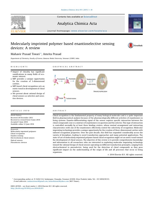
MIP-based chiral recognition sets an exotic trend in development of chiral sensors.
Analytica Chimica Acta 853 (2015) 1–18
Contents lists available at ScienceDirect
Analytica Chimica Acta
journal homepage: /locate/aca
Molecularly imprinted polymer based enantioselective sensing devices: A review
We present about rational design of chiral sensors as selective and sensitive devices.
GRAPArticle history: Received 20 December 2013 Received in revised form 8 June 2014 Accepted 9 June 2014 Available online 12 June 2014
ã 2014 Elsevier B.V. All rights reserved.
* Corresponding author at: N 16/62 E-K, Sudamapur, Vinayaka, Varanasi 221010, Uttar Pradesh, India. Tel.: +91 9450239133. E-mail addresses: mahavirtiwari@, krineshtiwari@ (M.P. Tiwari).
美国FDA指导原则CPGSEC585700根腐烂的薯片英文原版

美国FDA指导原则CPGSEC585700根腐烂的薯片英文原版Guidance for Industry: Control of Salmonella in Low-Moisture Food Establishments1. Introduction2. Background3. Good Agricultural PracticesLow-moisture food establishments should work closely with their potato suppliers to ensure that proper Good Agricultural Practices (GAPs) are followed. This includes proper storage, handling, and transportation of potatoes to minimize the risk of bacterial contamination. It is also essential to maintain proper documentation and traceability to identify potential sources of contamination.4. Hygiene and Sanitation PracticesEstablishments should have robust hygiene and sanitation practices in place to prevent cross-contamination and the spread of Salmonella. This includes thorough cleaning and sanitizing of equipment, surfaces, and utensils. Employees should follow good personal hygiene practices, such as proper handwashing and wearing protective clothing, to minimize the risk of introducing bacteria into the production area.5. Environmental MonitoringRoutine environmental monitoring should be conducted in low-moisture food establishments to detect the presence of Salmonella. This can be done through swabbing of surfaces, equipment, and the production environment. Regular sampling and testing of finished products should also be conducted to ensure the absence of Salmonella.6. Employee TrainingAll employees should receive proper training on food safety practices and be aware of the potential risks associated with Salmonella contamination. Training should include information on proper hygiene practices, sanitation procedures, and the importance of following established protocols to prevent contamination.7. Hazard Analysis and Critical Control Points (HACCP)Implementing a HACCP system can help low-moisture food establishments identify potential hazards and implement preventive measures. The seven principles of HACCP should be followed, including conducting a hazard analysis, determining critical control points, establishing critical limits, monitoring procedures, corrective actions, verification, and record-keeping.8. Supplier VerificationEstablishments should have a system in place to verify the safety of their potato suppliers. This includes conducting regular audits, requesting certificates of analysis, and verifying that suppliers have adequate food safety systems in place to minimize the risk of Salmonella contamination.9. Recall PlanLow-moisture food establishments should have a recall plan in place to respond quickly and effectively in the event of a product recall. The plan should outline the steps to be taken, including notifying regulatory authorities, conducting a thorough investigation, and issuing consumer notifications to ensure the safety of the public.10. Conclusion。
(生物科技行业类)密歇根大学生物系实验室的常用试剂配方

Table of ContentsLB Medium (1)NZ Medium (2)SM Buffer (3)SET Buffer (4)6X Prehyb Soln (5)10 X TBE (6)10 X TAE (7)20 X SSC (8)1% SDS, 0.2 M NaOH (9)14% PEG (8000), 2M NaCl, 10 mM MgSO4 (10)20% SDS (11)1.0 M Tris, pH 8.0, 1.5 M NaCl (12)10mM Tris-HCl, pH 7.5, 10mM MgSO4 (13)10 mM Tris, 50 mM EDTA, pH 7.5 (14)10 mM Tris-HCl, 1 mM EDTA, pH 7.5 (15)3 M Sodium Acetate, pH 4.8 (16)Electrophoresis dye (17)Labelling Stop dye (18)Sequencing gel dye (19)5% Acrylamide (20)6% Acrylamide in TBE, 50% Urea (21)40% Acrylamide (22)LB Medium (1 Liter)10g Bacto-tryptone5g Bacto-yeast extract10g NaClFor forty plates add 1% agar--1g. Autoclave media. When cool, add ampicillin and pour plates. For 1L of media, add 1.8 mL amp.NZ Medium (500 mL)5 g Bacto-tryptone2.5 g Bacto-yeast extract2.5 g NaCl1.25 g MgSO4For 20 plates add 1.2% agar--6g. Autoclave and pour plates at 50o CSM Buffer (1L)5.8 g NaCl1.2 g MgSo450 mL 1M Tris-HCl, pH 7.50.1 g Gelatin (doesn't dissolve)AutoclaveUsed for phage dilution and storage.SET Buffer50 mM Tris-HCl, pH 8.0, 50 mM EDTA, 20% w/v Sucroseto make 200mL:40 g Sucrose10 mL of 1M Tris20 mL of 0.5 M EDTA, disodium saltbring to 200 mL with H206X Prehybridization Solutionto make 500 mL300 mL ddH20150 mL 20X SSC50 mL 50X Denhardt's solution1 mL 0.5 M EDTA (disodium salt)2.5 mL 20% SDS6X refers to the concentration of SSC10X TBE Buffer (for polyacrylamide gels) to make one liter:60.75 g Tris3.7 g EDTA (tetrasodium salt)30 g Boric acid10X TAE Buffer (For agarose gels)to make one liter:48.20 g Tris6.75 g NaAce3.75 g EDTA (disodium salt)Adjust pH to 7.6 with acetic acid. (Approx. 20 mL)20X SSCto make one liter:175.3 g NaCl88.2 g NaCitrateadd water to bring volume to one liter.adjust to pH 7.0 with HCl.1% SDS, 0.2 M NaOHto make 100 mL:93 mL ddH205 mL 20% SDS2 mL 10 M NaOH14% PEG (8000), 2M NaCl, 10 mM MgSO4 to make one liter:140 g PEG117 g NaCl2.46 g MgSO4For use in phage DNA preparation.20% SDSto male 250 mL:50 g of SDS in a beakerAdd stir bar and H20 last.This solution will have to be heated for the SDS to dissolve.1.0 M Tris, pH 8.0, 1.5 M NaClto make one liter:121.1 g Trizma87.6 g NaClin a volume of water less than 1L. Adjust pH with HCl, then bring to 1L with H2010 mM Tris-HCl, pH 7.5, 10 mM MgSO4to make one liter:10 mL 1 M Tris-HCl2.46 g MgSO4for use in phage DNA preparation10 mM Tris, 50 mM EDTA, pH 7.5to make 200 mL:2 mL 1 M Tris20 mL 0.5 M EDTA (tetrasodium salt)178 mL ddH20adjust pH with HCl.10 mM Tris-HCl, 1 mM EDTA, pH 7.5to make 200 mL:2.0 mL 1 M Tris-HCl, pH 7.50.4 mL 0.5 M EDTA197.6 mL ddH203 M Sodium Acetate, pH 4.8to make one liter:408.1 g NaAce (trihydrate; gets cold in soln)about 700 mL H20adjust pH with glacial acetic acid (takes a lot)Measure tru pH by dilution with water; range will be between 4.8 and 5.5.Electrophoresis Dyeto make 4 mL:3 mL 50 mM EDTA, 10 mM Tris-HCl, pH 8.01 mL glycerol20 μL BPB10 μL Xylene cyanolStop dye for labelled probe1 mL 50 mM EDTA, 10 mM Tris, pH 7.5-8.5about 200 μl glyceroladd a few grains of blue dextran (8000)Sequencing gel dyefor approx 1 mL:1 mL formamide10 μL xylene cyanol10 μl BPB3 μL 10 M NaOH5% acrylamideto make 200 mL:20 mL 10X TBE25 mL 40% acrylamide155 mL H206% Acrylamide in TBE, 50% Ureato make 500 mL:50 mL 10X TBE75 mL 40% acrylamide250 g Ureabring to 500 mL with H2O40% Acrylamide (38:2 acrylamide:bis acrylamide) to make 200 mL:76 g acrylamide4 g bis acrylamidebring to 200 mL with H2O。
Native Instruments MASCHINE MIKRO MK3用户手册说明书

The information in this document is subject to change without notice and does not represent a commitment on the part of Native Instruments GmbH. The software described by this docu-ment is subject to a License Agreement and may not be copied to other media. No part of this publication may be copied, reproduced or otherwise transmitted or recorded, for any purpose, without prior written permission by Native Instruments GmbH, hereinafter referred to as Native Instruments.“Native Instruments”, “NI” and associated logos are (registered) trademarks of Native Instru-ments GmbH.ASIO, VST, HALion and Cubase are registered trademarks of Steinberg Media Technologies GmbH.All other product and company names are trademarks™ or registered® trademarks of their re-spective holders. Use of them does not imply any affiliation with or endorsement by them.Document authored by: David Gover and Nico Sidi.Software version: 2.8 (02/2019)Hardware version: MASCHINE MIKRO MK3Special thanks to the Beta Test Team, who were invaluable not just in tracking down bugs, but in making this a better product.NATIVE INSTRUMENTS GmbH Schlesische Str. 29-30D-10997 Berlin Germanywww.native-instruments.de NATIVE INSTRUMENTS North America, Inc. 6725 Sunset Boulevard5th FloorLos Angeles, CA 90028USANATIVE INSTRUMENTS K.K.YO Building 3FJingumae 6-7-15, Shibuya-ku, Tokyo 150-0001Japanwww.native-instruments.co.jp NATIVE INSTRUMENTS UK Limited 18 Phipp StreetLondon EC2A 4NUUKNATIVE INSTRUMENTS FRANCE SARL 113 Rue Saint-Maur75011 ParisFrance SHENZHEN NATIVE INSTRUMENTS COMPANY Limited 5F, Shenzhen Zimao Center111 Taizi Road, Nanshan District, Shenzhen, GuangdongChina© NATIVE INSTRUMENTS GmbH, 2019. All rights reserved.Table of Contents1Welcome to MASCHINE (23)1.1MASCHINE Documentation (24)1.2Document Conventions (25)1.3New Features in MASCHINE 2.8 (26)1.4New Features in MASCHINE 2.7.10 (28)1.5New Features in MASCHINE 2.7.8 (29)1.6New Features in MASCHINE 2.7.7 (29)1.7New Features in MASCHINE 2.7.4 (31)1.8New Features in MASCHINE 2.7.3 (33)2Quick Reference (35)2.1MASCHINE Project Overview (35)2.1.1Sound Content (35)2.1.2Arrangement (37)2.2MASCHINE Hardware Overview (40)2.2.1MASCHINE MIKRO Hardware Overview (40)2.2.1.1Browser Section (41)2.2.1.2Edit Section (42)2.2.1.3Performance Section (43)2.2.1.4Transport Section (45)2.2.1.5Pad Section (46)2.2.1.6Rear Panel (50)2.3MASCHINE Software Overview (51)2.3.1Header (52)2.3.2Browser (54)2.3.3Arranger (56)2.3.4Control Area (59)2.3.5Pattern Editor (60)3Basic Concepts (62)3.1Important Names and Concepts (62)3.2Adjusting the MASCHINE User Interface (65)3.2.1Adjusting the Size of the Interface (65)3.2.2Switching between Ideas View and Song View (66)3.2.3Showing/Hiding the Browser (67)3.2.4Showing/Hiding the Control Lane (67)3.3Common Operations (68)3.3.1Adjusting Volume, Swing, and Tempo (68)3.3.2Undo/Redo (71)3.3.3Focusing on a Group or a Sound (73)3.3.4Switching Between the Master, Group, and Sound Level (77)3.3.5Navigating Channel Properties, Plug-ins, and Parameter Pages in the Control Area.773.3.6Navigating the Software Using the Controller (82)3.3.7Using Two or More Hardware Controllers (82)3.3.8Loading a Recent Project from the Controller (84)3.4Native Kontrol Standard (85)3.5Stand-Alone and Plug-in Mode (86)3.5.1Differences between Stand-Alone and Plug-in Mode (86)3.5.2Switching Instances (88)3.6Preferences (88)3.6.1Preferences – General Page (89)3.6.2Preferences – Audio Page (93)3.6.3Preferences – MIDI Page (95)3.6.4Preferences – Default Page (97)3.6.5Preferences – Library Page (101)3.6.6Preferences – Plug-ins Page (109)3.6.7Preferences – Hardware Page (114)3.6.8Preferences – Colors Page (114)3.7Integrating MASCHINE into a MIDI Setup (117)3.7.1Connecting External MIDI Equipment (117)3.7.2Sync to External MIDI Clock (117)3.7.3Send MIDI Clock (118)3.7.4Using MIDI Mode (119)3.8Syncing MASCHINE using Ableton Link (120)3.8.1Connecting to a Network (121)3.8.2Joining and Leaving a Link Session (121)4Browser (123)4.1Browser Basics (123)4.1.1The MASCHINE Library (123)4.1.2Browsing the Library vs. Browsing Your Hard Disks (124)4.2Searching and Loading Files from the Library (125)4.2.1Overview of the Library Pane (125)4.2.2Selecting or Loading a Product and Selecting a Bank from the Browser (128)4.2.3Selecting a Product Category, a Product, a Bank, and a Sub-Bank (133)4.2.3.1Selecting a Product Category, a Product, a Bank, and a Sub-Bank on theController (137)4.2.4Selecting a File Type (137)4.2.5Choosing Between Factory and User Content (138)4.2.6Selecting Type and Character Tags (138)4.2.7Performing a Text Search (142)4.2.8Loading a File from the Result List (143)4.3Additional Browsing Tools (148)4.3.1Loading the Selected Files Automatically (148)4.3.2Auditioning Instrument Presets (149)4.3.3Auditioning Samples (150)4.3.4Loading Groups with Patterns (150)4.3.5Loading Groups with Routing (151)4.3.6Displaying File Information (151)4.4Using Favorites in the Browser (152)4.5Editing the Files’ Tags and Properties (155)4.5.1Attribute Editor Basics (155)4.5.2The Bank Page (157)4.5.3The Types and Characters Pages (157)4.5.4The Properties Page (160)4.6Loading and Importing Files from Your File System (161)4.6.1Overview of the FILES Pane (161)4.6.2Using Favorites (163)4.6.3Using the Location Bar (164)4.6.4Navigating to Recent Locations (165)4.6.5Using the Result List (166)4.6.6Importing Files to the MASCHINE Library (169)4.7Locating Missing Samples (171)4.8Using Quick Browse (173)5Managing Sounds, Groups, and Your Project (175)5.1Overview of the Sounds, Groups, and Master (175)5.1.1The Sound, Group, and Master Channels (176)5.1.2Similarities and Differences in Handling Sounds and Groups (177)5.1.3Selecting Multiple Sounds or Groups (178)5.2Managing Sounds (181)5.2.1Loading Sounds (183)5.2.2Pre-listening to Sounds (184)5.2.3Renaming Sound Slots (185)5.2.4Changing the Sound’s Color (186)5.2.5Saving Sounds (187)5.2.6Copying and Pasting Sounds (189)5.2.7Moving Sounds (192)5.2.8Resetting Sound Slots (193)5.3Managing Groups (194)5.3.1Creating Groups (196)5.3.2Loading Groups (197)5.3.3Renaming Groups (198)5.3.4Changing the Group’s Color (199)5.3.5Saving Groups (200)5.3.6Copying and Pasting Groups (202)5.3.7Reordering Groups (206)5.3.8Deleting Groups (207)5.4Exporting MASCHINE Objects and Audio (208)5.4.1Saving a Group with its Samples (208)5.4.2Saving a Project with its Samples (210)5.4.3Exporting Audio (212)5.5Importing Third-Party File Formats (218)5.5.1Loading REX Files into Sound Slots (218)5.5.2Importing MPC Programs to Groups (219)6Playing on the Controller (223)6.1Adjusting the Pads (223)6.1.1The Pad View in the Software (223)6.1.2Choosing a Pad Input Mode (225)6.1.3Adjusting the Base Key (226)6.2Adjusting the Key, Choke, and Link Parameters for Multiple Sounds (227)6.3Playing Tools (229)6.3.1Mute and Solo (229)6.3.2Choke All Notes (233)6.3.3Groove (233)6.3.4Level, Tempo, Tune, and Groove Shortcuts on Your Controller (235)6.3.5Tap Tempo (235)6.4Performance Features (236)6.4.1Overview of the Perform Features (236)6.4.2Selecting a Scale and Creating Chords (239)6.4.3Scale and Chord Parameters (240)6.4.4Creating Arpeggios and Repeated Notes (253)6.4.5Swing on Note Repeat / Arp Output (257)6.5Using Lock Snapshots (257)6.5.1Creating a Lock Snapshot (257)7Working with Plug-ins (259)7.1Plug-in Overview (259)7.1.1Plug-in Basics (259)7.1.2First Plug-in Slot of Sounds: Choosing the Sound’s Role (263)7.1.3Loading, Removing, and Replacing a Plug-in (264)7.1.4Adjusting the Plug-in Parameters (270)7.1.5Bypassing Plug-in Slots (270)7.1.6Using Side-Chain (272)7.1.7Moving Plug-ins (272)7.1.8Alternative: the Plug-in Strip (273)7.1.9Saving and Recalling Plug-in Presets (273)7.1.9.1Saving Plug-in Presets (274)7.1.9.2Recalling Plug-in Presets (275)7.1.9.3Removing a Default Plug-in Preset (276)7.2The Sampler Plug-in (277)7.2.1Page 1: Voice Settings / Engine (279)7.2.2Page 2: Pitch / Envelope (281)7.2.3Page 3: FX / Filter (283)7.2.4Page 4: Modulation (285)7.2.5Page 5: LFO (286)7.2.6Page 6: Velocity / Modwheel (288)7.3Using Native Instruments and External Plug-ins (289)7.3.1Opening/Closing Plug-in Windows (289)7.3.2Using the VST/AU Plug-in Parameters (292)7.3.3Setting Up Your Own Parameter Pages (293)7.3.4Using VST/AU Plug-in Presets (298)7.3.5Multiple-Output Plug-ins and Multitimbral Plug-ins (300)8Using the Audio Plug-in (302)8.1Loading a Loop into the Audio Plug-in (306)8.2Editing Audio in the Audio Plug-in (307)8.3Using Loop Mode (308)8.4Using Gate Mode (310)9Using the Drumsynths (312)9.1Drumsynths – General Handling (313)9.1.1Engines: Many Different Drums per Drumsynth (313)9.1.2Common Parameter Organization (313)9.1.3Shared Parameters (316)9.1.4Various Velocity Responses (316)9.1.5Pitch Range, Tuning, and MIDI Notes (316)9.2The Kicks (317)9.2.1Kick – Sub (319)9.2.2Kick – Tronic (321)9.2.3Kick – Dusty (324)9.2.4Kick – Grit (325)9.2.5Kick – Rasper (328)9.2.6Kick – Snappy (329)9.2.7Kick – Bold (331)9.2.8Kick – Maple (333)9.2.9Kick – Push (334)9.3The Snares (336)9.3.1Snare – Volt (338)9.3.2Snare – Bit (340)9.3.3Snare – Pow (342)9.3.4Snare – Sharp (343)9.3.5Snare – Airy (345)9.3.6Snare – Vintage (347)9.3.7Snare – Chrome (349)9.3.8Snare – Iron (351)9.3.9Snare – Clap (353)9.3.10Snare – Breaker (355)9.4The Hi-hats (357)9.4.1Hi-hat – Silver (358)9.4.2Hi-hat – Circuit (360)9.4.3Hi-hat – Memory (362)9.4.4Hi-hat – Hybrid (364)9.4.5Creating a Pattern with Closed and Open Hi-hats (366)9.5The Toms (367)9.5.1Tom – Tronic (369)9.5.2Tom – Fractal (371)9.5.3Tom – Floor (375)9.5.4Tom – High (377)9.6The Percussions (378)9.6.1Percussion – Fractal (380)9.6.2Percussion – Kettle (383)9.6.3Percussion – Shaker (385)9.7The Cymbals (389)9.7.1Cymbal – Crash (391)9.7.2Cymbal – Ride (393)10Using the Bass Synth (396)10.1Bass Synth – General Handling (397)10.1.1Parameter Organization (397)10.1.2Bass Synth Parameters (399)11Working with Patterns (401)11.1Pattern Basics (401)11.1.1Pattern Editor Overview (402)11.1.2Navigating the Event Area (404)11.1.3Following the Playback Position in the Pattern (406)11.1.4Jumping to Another Playback Position in the Pattern (407)11.1.5Group View and Keyboard View (408)11.1.6Adjusting the Arrange Grid and the Pattern Length (410)11.1.7Adjusting the Step Grid and the Nudge Grid (413)11.2Recording Patterns in Real Time (416)11.2.1Recording Your Patterns Live (417)11.2.2Using the Metronome (419)11.2.3Recording with Count-in (420)11.3Recording Patterns with the Step Sequencer (422)11.3.1Step Mode Basics (422)11.3.2Editing Events in Step Mode (424)11.4Editing Events (425)11.4.1Editing Events with the Mouse: an Overview (425)11.4.2Creating Events/Notes (428)11.4.3Selecting Events/Notes (429)11.4.4Editing Selected Events/Notes (431)11.4.5Deleting Events/Notes (434)11.4.6Cut, Copy, and Paste Events/Notes (436)11.4.7Quantizing Events/Notes (439)11.4.8Quantization While Playing (441)11.4.9Doubling a Pattern (442)11.4.10Adding Variation to Patterns (442)11.5Recording and Editing Modulation (443)11.5.1Which Parameters Are Modulatable? (444)11.5.2Recording Modulation (446)11.5.3Creating and Editing Modulation in the Control Lane (447)11.6Creating MIDI Tracks from Scratch in MASCHINE (452)11.7Managing Patterns (454)11.7.1The Pattern Manager and Pattern Mode (455)11.7.2Selecting Patterns and Pattern Banks (456)11.7.3Creating Patterns (459)11.7.4Deleting Patterns (460)11.7.5Creating and Deleting Pattern Banks (461)11.7.6Naming Patterns (463)11.7.7Changing the Pattern’s Color (465)11.7.8Duplicating, Copying, and Pasting Patterns (466)11.7.9Moving Patterns (469)11.8Importing/Exporting Audio and MIDI to/from Patterns (470)11.8.1Exporting Audio from Patterns (470)11.8.2Exporting MIDI from Patterns (472)11.8.3Importing MIDI to Patterns (474)12Audio Routing, Remote Control, and Macro Controls (483)12.1Audio Routing in MASCHINE (484)12.1.1Sending External Audio to Sounds (485)12.1.2Configuring the Main Output of Sounds and Groups (489)12.1.3Setting Up Auxiliary Outputs for Sounds and Groups (494)12.1.4Configuring the Master and Cue Outputs of MASCHINE (497)12.1.5Mono Audio Inputs (502)12.1.5.1Configuring External Inputs for Sounds in Mix View (503)12.2Using MIDI Control and Host Automation (506)12.2.1Triggering Sounds via MIDI Notes (507)12.2.2Triggering Scenes via MIDI (513)12.2.3Controlling Parameters via MIDI and Host Automation (514)12.2.4Selecting VST/AU Plug-in Presets via MIDI Program Change (522)12.2.5Sending MIDI from Sounds (523)12.3Creating Custom Sets of Parameters with the Macro Controls (527)12.3.1Macro Control Overview (527)12.3.2Assigning Macro Controls Using the Software (528)13Controlling Your Mix (535)13.1Mix View Basics (535)13.1.1Switching between Arrange View and Mix View (535)13.1.2Mix View Elements (536)13.2The Mixer (537)13.2.1Displaying Groups vs. Displaying Sounds (539)13.2.2Adjusting the Mixer Layout (541)13.2.3Selecting Channel Strips (542)13.2.4Managing Your Channels in the Mixer (543)13.2.5Adjusting Settings in the Channel Strips (545)13.2.6Using the Cue Bus (549)13.3The Plug-in Chain (551)13.4The Plug-in Strip (552)13.4.1The Plug-in Header (554)13.4.2Panels for Drumsynths and Internal Effects (556)13.4.3Panel for the Sampler (557)13.4.4Custom Panels for Native Instruments Plug-ins (560)13.4.5Undocking a Plug-in Panel (Native Instruments and External Plug-ins Only) (564)14Using Effects (567)14.1Applying Effects to a Sound, a Group or the Master (567)14.1.1Adding an Effect (567)14.1.2Other Operations on Effects (574)14.1.3Using the Side-Chain Input (575)14.2Applying Effects to External Audio (578)14.2.1Step 1: Configure MASCHINE Audio Inputs (578)14.2.2Step 2: Set up a Sound to Receive the External Input (579)14.2.3Step 3: Load an Effect to Process an Input (579)14.3Creating a Send Effect (580)14.3.1Step 1: Set Up a Sound or Group as Send Effect (581)14.3.2Step 2: Route Audio to the Send Effect (583)14.3.3 A Few Notes on Send Effects (583)14.4Creating Multi-Effects (584)15Effect Reference (587)15.1Dynamics (588)15.1.1Compressor (588)15.1.2Gate (591)15.1.3Transient Master (594)15.1.4Limiter (596)15.1.5Maximizer (600)15.2Filtering Effects (603)15.2.1EQ (603)15.2.2Filter (605)15.2.3Cabinet (609)15.3Modulation Effects (611)15.3.1Chorus (611)15.3.2Flanger (612)15.3.3FM (613)15.3.4Freq Shifter (615)15.3.5Phaser (616)15.4Spatial and Reverb Effects (617)15.4.1Ice (617)15.4.2Metaverb (619)15.4.3Reflex (620)15.4.4Reverb (Legacy) (621)15.4.5Reverb (623)15.4.5.1Reverb Room (623)15.4.5.2Reverb Hall (626)15.4.5.3Plate Reverb (629)15.5Delays (630)15.5.1Beat Delay (630)15.5.2Grain Delay (632)15.5.3Grain Stretch (634)15.5.4Resochord (636)15.6Distortion Effects (638)15.6.1Distortion (638)15.6.2Lofi (640)15.6.3Saturator (641)15.7Perform FX (645)15.7.1Filter (646)15.7.2Flanger (648)15.7.3Burst Echo (650)15.7.4Reso Echo (653)15.7.5Ring (656)15.7.6Stutter (658)15.7.7Tremolo (661)15.7.8Scratcher (664)16Working with the Arranger (667)16.1Arranger Basics (667)16.1.1Navigating Song View (670)16.1.2Following the Playback Position in Your Project (672)16.1.3Performing with Scenes and Sections using the Pads (673)16.2Using Ideas View (677)16.2.1Scene Overview (677)16.2.2Creating Scenes (679)16.2.3Assigning and Removing Patterns (679)16.2.4Selecting Scenes (682)16.2.5Deleting Scenes (684)16.2.6Creating and Deleting Scene Banks (685)16.2.7Clearing Scenes (685)16.2.8Duplicating Scenes (685)16.2.9Reordering Scenes (687)16.2.10Making Scenes Unique (688)16.2.11Appending Scenes to Arrangement (689)16.2.12Naming Scenes (689)16.2.13Changing the Color of a Scene (690)16.3Using Song View (692)16.3.1Section Management Overview (692)16.3.2Creating Sections (694)16.3.3Assigning a Scene to a Section (695)16.3.4Selecting Sections and Section Banks (696)16.3.5Reorganizing Sections (700)16.3.6Adjusting the Length of a Section (702)16.3.6.1Adjusting the Length of a Section Using the Software (703)16.3.6.2Adjusting the Length of a Section Using the Controller (705)16.3.7Clearing a Pattern in Song View (705)16.3.8Duplicating Sections (705)16.3.8.1Making Sections Unique (707)16.3.9Removing Sections (707)16.3.10Renaming Scenes (708)16.3.11Clearing Sections (710)16.3.12Creating and Deleting Section Banks (710)16.3.13Working with Patterns in Song view (710)16.3.13.1Creating a Pattern in Song View (711)16.3.13.2Selecting a Pattern in Song View (711)16.3.13.3Clearing a Pattern in Song View (711)16.3.13.4Renaming a Pattern in Song View (711)16.3.13.5Coloring a Pattern in Song View (712)16.3.13.6Removing a Pattern in Song View (712)16.3.13.7Duplicating a Pattern in Song View (712)16.3.14Enabling Auto Length (713)16.3.15Looping (714)16.3.15.1Setting the Loop Range in the Software (714)16.3.15.2Activating or Deactivating a Loop Using the Controller (715)16.4Playing with Sections (715)16.4.1Jumping to another Playback Position in Your Project (716)16.5Triggering Sections or Scenes via MIDI (717)16.6The Arrange Grid (719)16.7Quick Grid (720)17Sampling and Sample Mapping (722)17.1Opening the Sample Editor (722)17.2Recording Audio (724)17.2.1Opening the Record Page (724)17.2.2Selecting the Source and the Recording Mode (725)17.2.3Arming, Starting, and Stopping the Recording (729)17.2.5Checking Your Recordings (731)17.2.6Location and Name of Your Recorded Samples (734)17.3Editing a Sample (735)17.3.1Using the Edit Page (735)17.3.2Audio Editing Functions (739)17.4Slicing a Sample (743)17.4.1Opening the Slice Page (743)17.4.2Adjusting the Slicing Settings (744)17.4.3Manually Adjusting Your Slices (746)17.4.4Applying the Slicing (750)17.5Mapping Samples to Zones (754)17.5.1Opening the Zone Page (754)17.5.2Zone Page Overview (755)17.5.3Selecting and Managing Zones in the Zone List (756)17.5.4Selecting and Editing Zones in the Map View (761)17.5.5Editing Zones in the Sample View (765)17.5.6Adjusting the Zone Settings (767)17.5.7Adding Samples to the Sample Map (770)18Appendix: Tips for Playing Live (772)18.1Preparations (772)18.1.1Focus on the Hardware (772)18.1.2Customize the Pads of the Hardware (772)18.1.3Check Your CPU Power Before Playing (772)18.1.4Name and Color Your Groups, Patterns, Sounds and Scenes (773)18.1.5Consider Using a Limiter on Your Master (773)18.1.6Hook Up Your Other Gear and Sync It with MIDI Clock (773)18.1.7Improvise (773)18.2Basic Techniques (773)18.2.1Use Mute and Solo (773)18.2.2Create Variations of Your Drum Patterns in the Step Sequencer (774)18.2.3Use Note Repeat (774)18.2.4Set Up Your Own Multi-effect Groups and Automate Them (774)18.3Special Tricks (774)18.3.1Changing Pattern Length for Variation (774)18.3.2Using Loops to Cycle Through Samples (775)18.3.3Load Long Audio Files and Play with the Start Point (775)19Troubleshooting (776)19.1Knowledge Base (776)19.2Technical Support (776)19.3Registration Support (777)19.4User Forum (777)20Glossary (778)Index (786)1Welcome to MASCHINEThank you for buying MASCHINE!MASCHINE is a groove production studio that implements the familiar working style of classi-cal groove boxes along with the advantages of a computer based system. MASCHINE is ideal for making music live, as well as in the studio. It’s the hands-on aspect of a dedicated instru-ment, the MASCHINE hardware controller, united with the advanced editing features of the MASCHINE software.Creating beats is often not very intuitive with a computer, but using the MASCHINE hardware controller to do it makes it easy and fun. You can tap in freely with the pads or use Note Re-peat to jam along. Alternatively, build your beats using the step sequencer just as in classic drum machines.Patterns can be intuitively combined and rearranged on the fly to form larger ideas. You can try out several different versions of a song without ever having to stop the music.Since you can integrate it into any sequencer that supports VST, AU, or AAX plug-ins, you can reap the benefits in almost any software setup, or use it as a stand-alone application. You can sample your own material, slice loops and rearrange them easily.However, MASCHINE is a lot more than an ordinary groovebox or sampler: it comes with an inspiring 7-gigabyte library, and a sophisticated, yet easy to use tag-based Browser to give you instant access to the sounds you are looking for.What’s more, MASCHINE provides lots of options for manipulating your sounds via internal ef-fects and other sound-shaping possibilities. You can also control external MIDI hardware and 3rd-party software with the MASCHINE hardware controller, while customizing the functions of the pads, knobs and buttons according to your needs utilizing the included Controller Editor application. We hope you enjoy this fantastic instrument as much as we do. Now let’s get go-ing!—The MASCHINE team at Native Instruments.MASCHINE Documentation1.1MASCHINE DocumentationNative Instruments provide many information sources regarding MASCHINE. The main docu-ments should be read in the following sequence:1.MASCHINE MIKRO Quick Start Guide: This animated online guide provides a practical ap-proach to help you learn the basic of MASCHINE MIKRO. The guide is available from theNative Instruments website: https:///maschine-mikro-quick-start/2.MASCHINE Manual (this document): The MASCHINE Manual provides you with a compre-hensive description of all MASCHINE software and hardware features.Additional documentation sources provide you with details on more specific topics:►Online Support Videos: You can find a number of support videos on The Official Native In-struments Support Channel under the following URL: https:///NIsupport-EN. We recommend that you follow along with these instructions while the respective ap-plication is running on your computer.Other Online Resources:If you are experiencing problems related to your Native Instruments product that the supplied documentation does not cover, there are several ways of getting help:▪Knowledge Base▪User Forum▪Technical Support▪Registration SupportYou will find more information on these subjects in the chapter Troubleshooting.Document Conventions1.2Document ConventionsThis section introduces you to the signage and text highlighting used in this manual. This man-ual uses particular formatting to point out special facts and to warn you of potential issues.The icons introducing these notes let you see what kind of information is to be expected:This document uses particular formatting to point out special facts and to warn you of poten-tial issues. The icons introducing the following notes let you see what kind of information canbe expected:Furthermore, the following formatting is used:▪Text appearing in (drop-down) menus (such as Open…, Save as… etc.) in the software andpaths to locations on your hard disk or other storage devices is printed in italics.▪Text appearing elsewhere (labels of buttons, controls, text next to checkboxes etc.) in thesoftware is printed in blue. Whenever you see this formatting applied, you will find thesame text appearing somewhere on the screen.▪Text appearing on the displays of the controller is printed in light grey. Whenever you seethis formatting applied, you will find the same text on a controller display.▪Text appearing on labels of the hardware controller is printed in orange. Whenever you seethis formatting applied, you will find the same text on the controller.▪Important names and concepts are printed in bold.▪References to keys on your computer’s keyboard you’ll find put in square brackets (e.g.,“Press [Shift] + [Enter]”).►Single instructions are introduced by this play button type arrow.→Results of actions are introduced by this smaller arrow.Naming ConventionThroughout the documentation we will refer to MASCHINE controller (or just controller) as the hardware controller and MASCHINE software as the software installed on your computer.The term “effect” will sometimes be abbreviated as “FX” when referring to elements in the MA-SCHINE software and hardware. These terms have the same meaning.Button Combinations and Shortcuts on Your ControllerMost instructions will use the “+” sign to indicate buttons (or buttons and pads) that must be pressed simultaneously, starting with the button indicated first. E.g., an instruction such as:“Press SHIFT + PLAY”means:1.Press and hold SHIFT.2.While holding SHIFT, press PLAY and release it.3.Release SHIFT.1.3New Features in MASCHINE2.8The following new features have been added to MASCHINE: Integration▪Browse on , create your own collections of loops and one-shots and send them directly to the MASCHINE browser.Improvements to the Browser▪Samples are now cataloged in separate Loops and One-shots tabs in the Browser.▪Previews of loops selected in the Browser will be played in sync with the current project.When a loop is selected with Prehear turned on, it will begin playing immediately in-sync with the project if transport is running. If a loop preview starts part-way through the loop, the loop will play once more for its full length to ensure you get to hear the entire loop once in context with your project.▪Filters and product selections will be remembered when switching between content types and Factory/User Libraries in the Browser.▪Browser content synchronization between multiple running instances. When running multi-ple instances of MASCHINE, either as Standalone and/or as a plug-in, updates to the Li-brary will be synced across the instances. For example, if you delete a sample from your User Library in one instance, the sample will no longer be present in the other instances.Similarly, if you save a preset in one instance, that preset will then be available in the oth-er instances, too.▪Edits made to samples in the Factory Libraries will be saved to the Standard User Directo-ry.For more information on these new features, refer to the following chapter ↑4, Browser. Improvements to the MASCHINE MIKRO MK3 Controller▪You can now set sample Start and End points using the controller. For more information refer to ↑17.3.1, Using the Edit Page.Improved Support for A-Series Keyboards▪When Browsing with A-Series keyboards, you can now jump quickly to the results list by holding SHIFT and pushing right on the 4D Encoder.▪When Browsing with A-Series keyboards, you can fast scroll through the Browser results list by holding SHIFT and twisting the 4D Encoder.▪Mute and Solo Sounds and Groups from A-Series keyboards. Sounds are muted in TRACK mode while Groups are muted in IDEAS.。
开启片剂完整性的窗户(中英文对照)
开启片剂完整性的窗户日本东芝公司,剑桥大学摘要:由日本东芝公司和剑桥大学合作成立的公司向《医药技术》解释了FDA支持的技术如何在不损坏片剂的情况下测定其完整性。
太赫脉冲成像的一个应用是检查肠溶制剂的完整性,以确保它们在到达肠溶之前不会溶解。
关键词:片剂完整性,太赫脉冲成像。
能够检测片剂的结构完整性和化学成分而无需将它们打碎的一种技术,已经通过了概念验证阶段,正在进行法规申请。
由英国私募Teraview公司研发并且以太赫光(介于无线电波和光波之间)为基础。
该成像技术为配方研发和质量控制中的湿溶出试验提供了一个更好的选择。
该技术还可以缩短新产品的研发时间,并且根据厂商的情况,随时间推移甚至可能发展成为一个用于制药生产线的实时片剂检测系统。
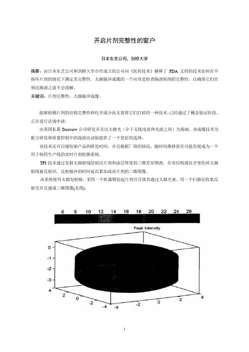
TPI技术通过发射太赫射线绘制出片剂和涂层厚度的三维差异图谱,在有结构或化学变化时太赫射线被反射回。
反射脉冲的时间延迟累加成该片剂的三维图像。
该系统使用太赫发射极,采用一个机器臂捡起片剂并且使其通过太赫光束,用一个扫描仪收集反射光并且建成三维图像(见图)。
技术研发太赫技术发源于二十世纪九十年代中期13本东芝公司位于英国的东芝欧洲研究中心,该中心与剑桥大学的物理学系有着密切的联系。
日本东芝公司当时正在研究新一代的半导体,研究的副产品是发现了这些半导体实际上是太赫光非常好的发射源和检测器。
二十世纪九十年代后期,日本东芝公司授权研究小组寻求该技术可能的应用,包括成像和化学传感光谱学,并与葛兰素史克和辉瑞以及其它公司建立了关系,以探讨其在制药业的应用。
虽然早期的结果表明该技术有前景,但日本东芝公司却不愿深入研究下去,原因是此应用与日本东芝公司在消费电子行业的任何业务兴趣都没有交叉。
这一决定的结果是研究中心的首席执行官DonArnone和剑桥桥大学物理学系的教授Michael Pepper先生于2001年成立了Teraview公司一作为研究中心的子公司。
TPI imaga 2000是第一个商品化太赫成像系统,该系统经优化用于成品片剂及其核心完整性和性能的无破坏检测。
未折叠蛋白反应的激活剂[发明专利]
![未折叠蛋白反应的激活剂[发明专利]](https://img.taocdn.com/s3/m/7ab793c70066f5335b812152.png)
专利名称:未折叠蛋白反应的激活剂
专利类型:发明专利
发明人:D·J·夏皮罗,P·J·赫甘罗斯尔,M·W·布德罗申请号:CN201980045131.2
申请日:20190701
公开号:CN112423743A
公开日:
20210226
专利内容由知识产权出版社提供
摘要:一组杀死治疗抗性ERα阳性乳腺癌细胞、卵巢癌细胞和子宫内膜癌细胞的小分子ERα生物调节剂。
由于与BHPI和其他常规治疗(内分泌治疗、三苯氧胺和氟维司群/ICI)相比,杀死治疗抗性乳腺癌细胞的能力增强,因此这些小分子具有增加的治疗潜力。
新化合物不仅抑制癌细胞的增殖,而且实际杀死癌细胞,从而防止多年后肿瘤的再激活。
申请人:伊利诺伊大学评议会
地址:美国伊利诺伊州
国籍:US
代理机构:北京北翔知识产权代理有限公司
更多信息请下载全文后查看。
欧洲药典7.5版

INDEX
To aid users the index includes a reference to the supplement in which the latest version of a text can be found. For example : Amikacin sulfate...............................................7.5-4579 means the monograph Amikacin sulfate can be found on page 4579 of Supplement 7.5. Note that where no reference to a supplement is made, the text can be found in the principal volume.
English index ........................................................................ 4707
Latin index ................................................................................. 4739
EUROPEAN PHARMACOPபைடு நூலகம்EIA 7.5
Index
Numerics 1. General notices ................................................................... 7.5-4453 2.1.1. Droppers...................
- 1、下载文档前请自行甄别文档内容的完整性,平台不提供额外的编辑、内容补充、找答案等附加服务。
- 2、"仅部分预览"的文档,不可在线预览部分如存在完整性等问题,可反馈申请退款(可完整预览的文档不适用该条件!)。
- 3、如文档侵犯您的权益,请联系客服反馈,我们会尽快为您处理(人工客服工作时间:9:00-18:30)。
Macrosegregation in direct-chill castingof aluminium alloysR.Nadella a ,D.G.Eskina,*,Q.Du a ,L.Katgerman b a Netherlands Institute for Metals Research,Mekelweg 2,2628CD,Delft,The Netherlandsb Delft University of Technology,Mekelweg 2,2628CD,Delft,The NetherlandsAbstractSemi-continuous direct-chill (DC)casting holds a prominent position in commercial aluminiumalloy processing,especially in production of large sized ingots.Macrosegregation,which is thenon-uniform chemical composition over the length scale of a casting,is one of the major defects thatoccur during this process.The fact that macrosegregation is essentially unaffected by subsequent heattreatment (hence constitutes an irreversible defect)leaves us with little choice but to control it duringthe casting stage.Despite over a century of research in the phenomenon of macrosegregation in cast-ings and good understanding of underlying mechanisms,the contributions of these mechanisms inthe overall macrosegregation picture;and interplay between these mechanisms and the structure for-mation during solidification are still unclear.This review attempts to fill this gap based on the pub-lished data and own results.The following features make this review unique:results of computersimulations are used in order to separate the effects of different macrosegregation mechanisms.The issue of grain refining is specifically discussed in relation to macrosegregation.This report isstructured as follows.Macrosegregation as a phenomenon is defined in the Introduction.In‘‘Direct-chill casting –process parameters,solidification and structure patterns’’section,direct-chillcasting,the role of process parameters and the evolution of structural features in the as-cast billetsare described.In ‘‘Macrosegregation in direct-chill casting of aluminium alloys’’section,macroseg-regation mechanisms are elucidated in a historical perspective and the correlation with DC castingprocess parameters and structural features are made.The issue of how to control macrosegregationin direct-chill casting is also dealt with in the same section.In ‘‘Role of grain refining’’section,theeffect of grain refining on macrosegregation is introduced,the current understanding is described and0079-6425/$-see front matter Ó2007Elsevier Ltd.All rights reserved.doi:10.1016/j.pmatsci.2007.10.001*Corresponding author.Tel.:+31152784463;fax:+31152786730.E-mail address:d.g.eskin@tudelft.nl (D.G.Eskin).Available online at Progress in Materials Science 53(2008)421–480422R.Nadella et al./Progress in Materials Science53(2008)421–480the contentious issues are outlined.The review isfinished with conclusion remarks and outline for the future research.Ó2007Elsevier Ltd.All rights reserved.Contents1.Introduction:macrosegregation (422)2.Direct-chill casting–process parameters,solidification and structure patterns (423)2.1.Direct-chill casting process–a brief introduction (423)2.2.Solidification patterns in DC cast billets (425)2.2.1.Characteristics of sump (425)2.2.2.Effect of DC casting process parameters (430)2.3.Flow patterns in DC cast billets (432)2.4.Structure patterns in DC cast billets (438)2.4.1.Grain size (439)2.4.2.Dendrite arm spacing(DAS) (443)2.4.3.‘Coarse-cell’grains (445)2.4.4.Porosity (448)2.4.5.Non-equilibrium eutectics (448)3.Macrosegregation in direct-chill casting of aluminium alloys (450)3.1.Segregation patterns in DC cast Al alloys and role of partition coefficient (451)3.2.Mechanisms of macrosegregation (453)3.2.1.Historical overview (454)3.2.2.Shrinkage-induced flow (456)3.2.3.Thermo-solutal and forced convection (457)3.2.4.Movement of equiaxed grains(‘floating’grains) (460)3.2.5.Deformation of solid network (463)3.3.Macrosegregation–influence of process parameters and structure (464)4.Role of grain refining (467)4.1.Basics of grain refinement (468)4.2.Structure formation and permeability in grain-refined Al alloys (469)4.3.Effect of grain refining on macrosegregation–issues (473)5.Concluding remarks (476)Acknowledgements (477)References (477)1.Introduction:macrosegregationCasting techniques for wrought aluminium alloys are characterized by their productiv-ity and the quality of the as-cast product.With reference to quality,segregation,an inho-mogeneous distribution of alloying elements on different length scales,is characteristic of all cast products.It is well known that the solidification of alloys is accompanied by a cer-tain degree of microsegregation of alloying elements due to their partitioning between liquid and solid phases during solidification,and due to the non-equilibrium nature of solidification.If,subsequently,gross relative movement between the liquid and the solid occurs,the segregation can appear on a macro-scale,which is called macrosegregation.R.Nadella et al./Progress in Materials Science53(2008)421–480423 Thus macrosegregation can be defined as the spatial non-uniformity in the chemical composition on the scale of a solidified casting.The concentrations of alloying elements may vary substantially throughout the cross-section of the casting.In the extreme case, the composition in certain regions across the thickness of the ingot(billet)may be outside the registered limits established for the alloy.Although microsegregation(where diffusion distances are at the order of magnitude of the dendrite arm spacing or the cell size,usually between10and100l m)can be minimised/eliminated by heat treatments(e.g.homogeni-sation),the length scales associated with macrosegregation(cm to m)make it essentially unaffected by annealing.Hence it constitutes an irreversible defect.This defect may then persist throughout the downstream processing of the ingot(billet).This may influence heat treatment efficiency,lead to property variations,and impair the quality of thefinished end product.More importantly,the occurrence of this defect can seriously limit the size,alloy composition and the allowable speed(as a consequence,the productivity)at which direct chill(DC)cast billets(ingots)are produced.The degree of macrosegregation in an alloy is influenced to a large extent by ingot dimensions,type and amount of alloying elements and the casting process used.Contin-uous or semi-continuous casting routes are commonly used to produce ingots of wrought alloy compositions,which are intended for subsequent processing[1–6].Moreover,the semi-continuous direct-chill casting is the most efficient technology for the production of large-sized ingots needed for sheet and forged products.The presence of macrosegrega-tion sets limitations on the size and the composition of the billet to be cast in a productive and economical way.Thus the importance of macrosegregation in the production of cast products cannot be overemphasized.Macrosegregation and hot cracking are considered as major defects in DC cast Al alloys and the occurrence of these two defects is connected through solidification phenomena.In general,it is known that macrosegregation is more influenced by convective and shrinkage-inducedflows in the semi-solid region of the ingot (billet)[3,7–11].Hot cracking can initiate under certain conditions in the lower part of the semi-solid region,close to the solidus isotherm,when the solid fraction is more than0.9. The subject of hot cracking in Al alloys has been extensively reviewed recently[12].This literature review is confined to macrosegregation in Al alloys and is structured as follows.In Section2,the DC casting process is introduced to the reader;the role of pro-cess parameters,theflow and solidification patterns are explained and related to structure evolution in as-cast billets(ingots).Subsequently in Section3,the problem of macroseg-regation is defined;the mechanisms underlying macrosegregation are illustrated with the aid of computer simulations.The correlation with DC cast process parameters and struc-tural features is attempted(Section3).The issue of how to control macrosegregation is also dealt in Section3.In Section4,the effect of grain refining on macrosegregation is introduced,the current understanding is described and the contentious issues are outlined. The review ends with concluding remarks.2.Direct-chill casting–process parameters,solidification and structure patterns2.1.Direct-chill casting process–a brief introductionDirect-chill(DC)casting of aluminium was invented in1936–1938almost simulta-neously in Germany(W.Roth,VAW)and the USA(W.T.Ennor,ALCOA).This technol-ogy was based on the existing methods of casting for copper and aluminium alloyssuggested by Zunkel(1935)and Junghans(1933).Rapid development and industrial use of this method of casting was facilitated by requirements of the aircraft industry for large bil-lets(both round andflat).This demand wasfirst driven by increasing passenger airline transport and,later by military needs during World War II.By the end of the war,almost all wrought aluminium was produced by direct-chill casting in the United States,the Soviet Union,and Germany.Excellent reviews are available on the technological developments together with the insights into the process[1,2,4,13].Typical DC cast products include large rectangular sec-tions known as ingots(approx.500·1500–2000mm which are further rolled into plate, sheet and foil)and cylindrical sections known as billets(up to1100mm in diameter which are further forged or extruded to form rods,bars,tubes and wires).In this review we will use these names interchangeably,if not stated otherwise.During DC casting,liquid metal is poured into a water-cooled mould,which is initially closed by a starting block beneath.Once the liquid metal freezes on the starting block and a solid shell is formed close to the mould walls,the starter block is lowered into a pit with a constant casting speed V cast while keeping the metal level in the mould at a certain height. The solid shell forms due to the heatflow through the water-cooled mould(primary cool-ing).While the outer part of the ingot is now solid,the inner core is still semi-solid/liquid. Further cooling of the ingot bulk to a temperature below the alloy solidus is achieved by quenching(cooling,chilling)the solid shell directly with water jets(Fig.1)as the ingot des-cends beneath the lower edge of the mould(secondary cooling,which actually provides up to95%heat extraction[13]).In a vertical process,the casting stops when the bottom of the pit is reached.A horizontal variant of the process can be truly continuous withflying saws separating completely solid part throughout the casting duration.Surface quality and microstructure have received a lot of attention in DC casting tech-nology.Mould lubrication and airflushing are used to separate the solid shell from the mould,to control primary cooling rate,and to minimise sticking.Interaction betweenthe(semi-)solid shell and the mould may cause a rough surface with different typeofFig.1.Schematic of the DC cast process.Main process parameters are underlined. 424R.Nadella et al./Progress in Materials Science53(2008)421–480R.Nadella et al./Progress in Materials Science53(2008)421–480425 defects,such as cold shuts,bleed-outs,and drag marks.As will be discussed later,the sur-face region of the DC cast material is characterized by a mixedfine/coarse microstructure with a cyclic macrostructural pattern[6,13,14].In addition there is a specific macrosegre-gation pattern with large variations in chemical composition at the surface/subsurface. This affects the quality of the surface and subsurface layers and can lead to problems dur-ing downstream processing,e.g.edge cracking and streaking during rolling and extrusion. The billet needs to be‘‘scalped’’by removing the surface layer.Thus it is much more eco-nomical to produce good enough cast surfaces for direct working without or with mini-mized prior scalping.To counter the above undesirable effects,several mould technologies such as low-head casting,hot top casting,lubrication through the mould,air pressurised moulds,electro-magnetic casting(EMC),etc.have been devised with the aim to control the mould(pri-mary)cooling[13].The hot top,most widely used nowadays in DC casting moulds,is a refractory reservoir with a ceramic insert in the mould.This type of moulds was pioneered by Moritz(Reynolds,1958)and further developed by Furness and Harvey(British Alu-minium,1973).The hot top eliminates the need of thorough control of melt level in the mould and makes the process more manageable[4].Further control of the primary cooling by constant air/oil supply through afine-porous graphite ring was suggested by Mitamura and Itoh(Showa Denko,1977)and mastered by WagstaffInc.in the1980s.The main improvement was the surface quality.Electromagnetic casting(EMC)goes one step fur-ther and is based on the concept of mould-less casting,in which the liquid metal is con-strained by an electromagneticfield while it is chilled by water jets[15].This technology was invented by Getselev(Kuibyshev Aluminium Works,1969).The most obvious advan-tage of this method is the production of very smooth surfaces in billets that can be directly processed.In addition,eddy currents in the melt alter theflow patterns,which have imme-diate effect on structure and macrosegregation.More discussion on EMS will follow in the later sections.The main DC cast process variables are casting speed(the speed at which the solid is withdrawn from the mould),water-flow rate(the cooling rate),and the melt temperature (level of melt superheat).The optimum casting speed depends on the alloy composition and the casting size,and is usually between3and20cm/min.The waterflow rate ranges from2000to4000mm3/s per1mm of the mould circumference[13],which equals to75–150l/min for a200-mm circular mould.Typical melt temperatures are in the range of690–725°C for commercial Al alloys.2.2.Solidification patterns in DC cast billets2.2.1.Characteristics of sumpThe process variables determine thermal conditions of casting and,therefore the tem-perature distribution in different sections of the billet.Together with the alloy composition this decides the dimensions and geometry of the transition,between liquid and solid, region in the billet.The billet during casting comprises several,well defined zones as shown in Fig.2.The sump consists of the liquid pool(1)and the transition region(2).The tran-sition region is bound by liquidus and solidus isotherms and can be further subdivided into the slurry and the mushy(3)zones with the border between them represented by a coher-ency isotherm(e.g.at a solid fraction of0.3in Fig.2a).The condition of coherency can be defined as the moment(or temperature)when solid grains(usually dendrites)start toFig.2.Schematic representation of the transition region:(a)illustration of the liquidus(L)and solidus(S)isotherms in a typical DC cast round billet.Coherency isotherm is marked as30%.The liquid pool depth(1),transition region(2),mushy zone(3),and the sump depth (1+2)are indicated in the diagram,and(b)regions in which different macrosegregation mechanisms are operating.426R. Nadella et al. / Progress in Materials Science 53 (2008) 421–480R.Nadella et al./Progress in Materials Science53(2008)421–480427 impinge upon one another,forming a macroscopically coherent structure[16],as shown schematically in Fig.2b.In this paper,reference to the mushy zone is always made to the region below the coherency isotherm,while the region between the liquidus and the coherency isotherms is called a slurry.For wrought commercial Al alloys used in DC cast-ing,the solid fraction at which this transition occurs is between0.2and0.33[16].The coherency isotherm in most cases outlines the(continuous)solidification front.The solid-ification front and the isotherms indicate the progress of solidification in thermal and geo-metrical terms.Different mechanisms of macrosegregation are acting in different zones of the transition region as shown in Fig.2b and will be discussed in detail later in this review.The depth of the sump(defined as the distance along the ingot/billet centreline from the bottom of the hot top(see Fig.1)to the solidus isotherm)is one of the characteristic fea-tures of the solidification profile that exists upon DC casting(Fig.2a).The sump depth mainly depends on casting speed,alloy type and size of the casting and is typically around 0.7times the billet radius[5,13].For the billet,the sump depth(h)increases with the square of the radius(R),linearly with casting speed and is inversely proportional to the alloy ther-mal conductivity according to the following formula[1,17]h¼½AR2V cast =½4k sðT mÀT surfÞ ;ð1Þwhere A is a coefficient depending on the alloy(latent heat of fusion,density of solid,spe-cific heat of solid),V cast is the casting speed,k s is the thermal conductivity of solid,T m is the melting temperature of the alloy,and T surf is the surface temperature of the billet(or water temperature).The coefficient A determines the solidus temperature of the alloy.A similar relationship can be derived forflat ingots,with ingot thickness substituting for billet radius in Eq.(1).Although this formulation is derived based on the assumption of the constant surface temperature and conical shape of the sump,it proves to be valid in practice [1,5,18].The sump depth normalized to the billet radius is shown to increase linearly with the increasing thermal Peclet number,1which means that the sump depth is inversely pro-portional to the alloy thermal conductivity[5,13].The direct consequence of Eq.(1)is the rule that the ratio between the sump depth and the billet radius is constant if V cast R¼const½1;5 :ð2ÞIn practice the casting speed is reduced as the diameter(or thickness)increases.The dimensions of the transition region are not,however,changing uniformly along the billet cross-section.There is a general tendency of widening the transition region towards the centre of the casting.The solidification of the billet follows an interesting pattern due to the specifics of the DC casting process.The billet surface solidifies in the mould under the influence of pri-mary cooling(Fig.3).At some point above the base of the mould,the shell shrinks away from the mould due to thermal contraction of the ingot,forming an air gap(which depends on the mould design).This air gap drastically reduces the heat extraction through the mould,which may even lead to partial re-melting of the shell.Thus the subsurface is formed under decreased heat extraction.Once the secondary cooling takes effect,the next inner layer is solidified under high cooling rates,where water jets hit the surface.From 1Peclet number=LV/a,where L is the characteristic length(billet radius),V is the velocity(casting speed),and a is the thermal diffusivity(k/q c p)where k,q,c p are thermal conductivity,density,and heat capacity,respectively. This number shows the ratio between heat advection and heat conduction on the same length scale.then onwards,the cooling rate decreases as the centre is approached.If the mould is deep and metal level is high,then the air gap will extend over a greater length with the risk of surface defects through local collapse of the weak solid network or bleed-outs [4].In addition to this cooling rate (defined as the inverse of the time required to pass the solidification range,which is determined mainly by heat transfer conditions),the billet structure is also influenced by another factor called ‘solidification rate’(or growth rate i.e.,the normal velocity of the solidification front,V sol )which depends on the geometry of the solidification front (sump shape in the case of DC casting).This is proportional to the casting speed and is given byV sol ¼V cast cos u ;ð3Þwhere u is the angle between the normal to the solidification front and the billet axis [5].Though the casting speed and cooling conditions are presumed constant during steady-state casting,the local solidification rate and the thermal gradient (G )change with position along the solidification front (Fig.4a)[1,5,19].The solidification rate is maximum in the centre and on the periphery of the billet,where the angle u is nil.The sump profile can be observed experimentally by doping the melt during casting with liquid of different composition [2],by addition of a grain refiner [20,21],or by emp-tying the sump during casting [5,22](Fig.4b).Fig.3.Interruption of mould cooling and air gap formation during solidification of the ingot shell upon DC casting [4].(a)Primary (mould)cooling;(b)interruption of mould cooling owing to formation of air gap;(c)secondary (direct water)cooling.428R.Nadella et al./Progress in Materials Science 53(2008)421–480The cooling rate is an important characteristic that determines to a great extent the structure and stress evolution in the as-cast material.It is a measure of heat extraction and varies throughout the transition region,both in vertical and horizontal directions.There is a general decrease of the cooling rate towards the centre of the billet with a fre-quently experimentally observed sudden increase in the very centre [5].In the vertical direction,the cooling rate is lower in the slurry zone and much higher in the mushy zone[23].Several reasons can be behind these observations.First of all,the overall shape of the cooling curve can be explained by the extension of the slurry region.The temperature variation within the slurry region is rather small whereas its width is increasing towards the billet centre (Figs.2a and 4a).The rate of solid phase formation in aluminium alloys is,however,very high,which means that over 30%of the solid phase can be formed within a few degrees below the liquidus.The formation of the solid phase produces latent heat of solidification and pumps additional thermal energy into the slurryzone,Fig.4.(a)Scheme of isotherms,solidification rate and thermal gradient distributions during DC casting,and (b)experimentally observed sump profile outlined by addition of a grain refiner (200-mm billet of a 6061alloy).R.Nadella et al./Progress in Materials Science 53(2008)421–480429430R.Nadella et al./Progress in Materials Science53(2008)421–480effectively slowing down the cooling.As a result a nearly isothermal plateau appears in thefirst portion of the cooling curve and becomes longer on approaching the billet cen-tre.Secondly,the central part of the billet is formed in the last stage of solidification. This means that the amount of latent heat that is released in a particular horizontal cross-section of the billet decreases towards the bottom of the sump,as most of the lower cross-section has been already solidified and does not release latent heat anymore.There-fore,the cooling in the central–bottom part of the mushy zone(second portion of the cooling curve)is more efficient than in the slurry zone.Four factors may further enhance the acceleration of cooling in the central part of the billet as compared to an intermediate radial(thickness)position.(i)The lower part of the sump(central portion of a billet)is formed,in most cases,in the range of secondary and downstream cooling(Fig.1)where the heat transfer is the highest.(ii)In addition,the heat is extracted from this part of the billet mostly through the solid phase that has a higher heat conductivity than the liquid. (iii)Some influence can be imposed by meltflow in the liquid/slurry part of the billet(see Section2.3).Hotter melt penetrates the slurry region about the mid-radius,possibly impeding the cooling efficiency.However,in the central–bottom part of the slurry zone, the colder melt is driven upwards,additionally cooling the melt in this section of the billet.(iv)And,finally,the high solidification-front velocity in the centre of the billet (Eq.(3))may narrow the mushy zone as a result of a higher upward velocity of the solidus isotherm as compared to the liquidus velocity.One should be very careful in attributing the measured cooling curve to the actual cool-ing rate that determines the structure formation in the solidification range.It is true that if we take the temperature measurement versus casting length and assume a constant casting speed,we can recalculate the data in terms of temperature versus time.But this‘‘cooling rate’’can be related to the formed structure only if the solid phase follows the tip of a ther-mocouple,in other words–travels from the liquidus to the solidus at the casting speed. The actual situation in the sump of the billet(ingot)is more complicated with thermo-sol-utal convection and gravity involved and with the resultant complexflow patterns that exist in the liquid and slurry zones of the billet(see Section2.3).The inhomogeneous dis-tribution of cooling rates in the transition region is reflected in the inhomogeneous struc-ture found in different sections of the billet.In general,the cooling rate encountered in a commercial size DC cast ingot varies from 0.4to10K/s[24].2.2.2.Effect of DC casting process parametersOut of all DC casting process parameters,casting speed exerts a dominant influence on the depth and shape of the sump,a fact that has been noticed by the pioneers of this tech-nology[1,17].Increase in casting speed causes sharp deepening of the sump by changing both the sump depth and the distance between liquidus and the solidus isotherms(1+2 and2in Fig.2a)with other isotherms in the transition region moving further apart (Fig.5a and b).However,across the billet cross-section,the vertical distance between liq-uidus and solidus changes with casting speed unevenly in the radial direction(Fig.5c).So the effect of increasing casting speed is much more pronounced in the central part of the billet.Earlier discussion on the sump depth pertains to the steady-state regime(a situation where the sump depth and the position of the isotherms are invariant with time).As a rule of a thumb,the steady state is considered to be reached after a length equal to one billet432R.Nadella et al./Progress in Materials Science53(2008)421–480diameter is cast after the point where the casting speed is varied.Recent calculations on the evolution of sump depth with time in a transient state(during changing casting speed) showed that the steady-state constant depth is reached even before the billet-diameter length[25].A transient casting regime with continuous change of casting speed results in thermal inertia with correspondingly delayed development of sump,which has been experimentally and numerically shown in a number of studies,e.g.[25–27].As a result, the depth of the sump can‘‘overshoot’’,i.e.the depth keeps increasing at a constant or even decreasing casting speed.In comparison with casting speed,waterflow rate and melt temperature exert less influ-ence on the sump dimensions.It is experimentally shown that the change in waterflow rates has almost no effect on the characteristics of the sump,especially at high casting speeds[18].At lower casting speeds,the sump depth and the width of the transition region in the billet centre tend to increase with waterflow[18].However,a slight decrease in sump depth is reported at high waterflow rates and at low melt superheats,evidently due to the overall increase in heat extraction[28].Generally,waterflow rate has marginal effect2on the temperature distribution provided that thisflow rate is sufficient to assure the nucleate boiling regime when the heat transfer coefficient is the highest[13,29],which is normally the case during DC casting.Increase in melt temperature can deepen the sump due to the increase in total heat that needs to be removed via the heat transfer through the surface,and raised temperature gradients in the liquid pool[30–32].Computer simulations of direct-chill casting confirm that the increase in melt temperature deepens the sump(region1+2,see Fig.2a)and nar-rows the transition region(region2)by shifting both the liquidus and the solidus isotherms downwards[25,33].But liquidus position is affected to a greater extent.At the periphery of the billet the solidus tends to move downwards with increasing melt temperature and this can often result in bleed-outs during DC casting[33].Generally,a lower melt temperature results in a shallower and more isothermal sump.2.3.Flow patterns in DC cast billetsOne of the main causes of macrosegregation is the relative movement between solid and liquid phase.As we did in the previous section,it is convenient to divide the solidifying zone into two parts by the so-called coherence fraction contour:a slurry zone in which the solid phase isfloating or suspended in the liquid and a mushy zone where the solid forms a coherent network and moves uniformly downwards at a specified speed(casting speed)(Fig.2).Theflow patterns in these two parts are different.In the slurry zone,the volume fraction of solid grains is in the range between0and the coherency fraction(which is e.g.between0.2and0.3).The drag force imposed on the liquid phase by the solid is rel-atively small and theflow characteristics are mainly determined by forced convection and thermal–solutal(natural)convection.The forced convection can be a result offilling con-ditions and there are different inlet and melt distribution designs to ensure a stable and 2If the Biot number,Bi(given by hd/kwhere h is the heat transfer coefficient,d is the distance from the surfacesand k s is the thermal conductivity of the solid)is greater than1,heatflow is dominated by conduction(k s).With typical values for h(104W mÀ2KÀ1),and k s(150W mÀ1KÀ1),the critical distance is15mm from the surface. Deeper inside the billet,the heatflow is controlled by convection.。