墙壁式WIFI路由器用户手册
思科 WAP361 Wireless-AC N 双无线电墙壁式接入点快速入门指南说明书

Quick Start GuideCisco WAP361 Wireless-AC/N Dual Radio Wall Plate Access Point with PoEWelcomeThank you for choosing the Cisco WAP361 Wireless-AC/N Dual Radio Wall Plate Access Point with PoE. The Cisco WAP361 is an indoor concurrent dual-band radio 802.11ac and 802.11n access point with integrated PoE switch. -PoE Supplied by UL Listed I.T.E.This guide provides the general layout of the Cisco WAP361, describe how to deploy the Cisco WAP361 in your network, and describe how to configure the Cisco WAP361. For additional information, see/go/300_wap_resources.Package Contents•Wireless Access Point•Mounting Kit•This Quick Start Guide•Ethernet Cable•T echnical Support Contact•Pointer Card China RoHS•EU Directives 1999/5/EC Compliance Information (for EU SKU only) Before You Begin1Before you begin the installation, make sure that you have the following equipment and services:• A computer with browser support for:–Internet Explorer 7.0 or later–Chrome 5.0 or later–Firefox 3.0 or later–Safari 3.0 or later•T ools for installing the hardware•FindIt tool for locating the access point•One or more Ethernet network switches with PoE•Mobile devices (iPhone, Android, etc.) via wireless setup SSID.(Configure via Wi-Fi mobile device with a web browser.)2Cisco WAP361 Quick Start GuideCisco WAP361 Features2Front PanelThe front panel of the Cisco WAP361 consists of one system LED. For full descriptions of the colors of the lights and their indications, see “Verifying the Hardware Installation”.Back PanelRESET—See “Rebooting the Cisco WAP361 or Resetting to Factory Defaults” for information on the RESET button.PD/LAN0—The Powered Device (PD/LAN0) port is used to power the Cisco WAP361 using PoE.Right-Side PanelThe right-side panel of the Cisco WAP361 has a Kensington lock slot. You can use it to attach a cable and lock to the Cisco WAP361.48V DC—The 48V DC jack is used to connect the power adapter to the Cisco WAP361 if you are not using PoE.Top PanelThe top panel of the Cisco WAP361 has the security screw hole.Bottom PanelPSE—The Power Sourcing Equipment (PSE) port is used to power the device that is connected to the Cisco WAP361 through this port.LAN1-4—The RJ-45 Ethernet port is an auto-sensing, Gigabit Ethernet (802.3) port used to connect the Cisco WAP361 to network devices, such as computers, routers, or switches. We strongly recommend that you use a Category 5e or better cable for gigabit connectivity.Default SettingsParameter Default ValueUsername ciscoPassword ciscoLAN IP Address DHCP address assigned by serverFallback LAN IP192.168.1.245Subnetwork Mask255.255.255.0Cisco WAP361 Quick Start Guide34Cisco WAP361 Quick Start GuideIf you are using a Cisco RV series router, the default range for the DHCP assigned address is from 192.168.1.100 to 192.168.1.254. Any device connecting to the same LAN will be assigned an IP address in this range.Mounting the Cisco WAP361•We recommend that you mount the Cisco WAP361 to a wall or junction box.Placement Tips•Ambient Temperature —T o prevent the Cisco WAP361 fromoverheating, do not operate it in an area that exceeds an ambient temperature of 104°F (40°C).•Air Flow —Both side panels have vents that must be unobstructed to prevent overheating.•Mechanical Loading —The Cisco WAP361 should be level, stable, and secure to prevent it from sliding or shifting out of position.Wall MountingCisco WAP361 access points can be mounted on walls and junctionboxes, in the vertical orientation with the security screw on the top and the LED which is located above the Cisco logo.3Cisco WAP361 Quick Start Guide 5S TEP 1If you are mounting the AP directly to a junction box, go to Step 3.For wall mounting, use the mounting bracket as a template to mark the locations of the mounting holes on the bracket. Figure 1 shows the dimensions of the mounting bracket.C AUTION T o ensure a safe and secure installation, make sure you are using adequate screws and mount the access point using noless than two screws.Figure 1Mounting Bracket DimensionsS TEP2For wall mounting, drill four pilot holes at the mounting hole locations you have marked (at opposite corners of the bracket),and use appropriate anchors as required.N OTE The pilot hole size varies according to the material, and itsthickness, you are fastening. Cisco recommends that you test thematerial to determine the ideal hole size for your mountingapplication.S TEP3Feed the cable(s) from the junction box / wall through the large center cable access hole in the bracket, with the words “NOTICEWALL MOUNT ONL Y” facing you as shown in Figure2.Figure2Bracket Mounting DirectionS TEP4Position the mounting bracket mounting holes (with the words “NOTICE WALL MOUNT ONL Y” facing you) over the screw holes.S TEP5Insert a screw into each mounting hole and tighten.N OTE Screws supplied in kit (see Figure3) may not be appropriatefor all mounting options. You may need to obtain screws which fityour custom installation.6Cisco WAP361 Quick Start GuideCisco WAP361 Quick Start Guide 7Figure 3Mounting Bracket Screw DimensionsN OTE Make sure all cables are clear and the bracket sits flushagainst the wall / junction box. The joint created with the screwsmust have a minimum pullout force of 20 lbs (9 kg).S TEP 6Connect the Ethernet cable and the power cable (optional) to theaccess point.S TEP 7With the access point’s LAN1-4 ports facing down and the rearmetal side of the access point facing the bracket, gently slide the access point onto the bracket. If properly done, the Kensingtonlock slot on the AP and the security screw hole on the mountingbracket will be aligned.S TEP 8Insert the security screw (see Figure 4) into the hole on the top ofthe access point and tighten it till the screw head is flush with the access point's body (see Figure 2). The security screw isprovided in the Mounting Kit.Figure 4Security Screw DimensionsAll dimensions in millimeters (mm).Connecting the Cisco WAP3614You can perform the initial configuration using either a wired or wireless connection. The default configuration of the Cisco WAP361 has the Wi-Fi radio turned on.T o connect the Cisco WAP361 to the wired network:S TEP1Connect the Ethernet cable to the Ethernet port of a switch, a router, or a PC.S TEP2Connect the other end of the network Ethernet cable to the Ethernet port of the Cisco WAP361.S TEP3If PoE is not provided, plug in the supplied power adapter to provide power to the Cisco WAP361.This wireless default configuration will not allow traffic between WiFi and Ethernet; users will need to go through the setup wizard to resume the traffic between WiFi and Ethernet.T o connect the Cisco WAP361 to the network wirelessly:S TEP1Use wireless clients to locate the WAP361’s SSID (CiscoSB-Setup). S TEP2Use the ‘cisco123’ passkey to access the access point.N OTE The system provides a one-time-only access to configure the access point using a wireless connection.After installation, all lights should be active. Refer to Verifying the Hardware Installation for details about the different lights on the Cisco WAP361.8Cisco WAP361 Quick Start GuideCisco WAP361 Quick Start Guide 9Verifying the Hardware InstallationT o verify the hardware installation, complete the following tasks:•Check the cable connections.•Check the state of the indicator light.N OTE If you need help resolving a problem, visit the Cisco Support Community at /go/smallbizsupport . Label Activity Description Power OffThe WAP361 is out of power.Solid GreenThe Cisco WAP361 is normal; no wireless client connected.Solid BlueThe Cisco WAP361 is normal; at least one wireless client connected.Solid RedThe Cisco WAP361 fails to boot with both firmware images.Flashing GreenThe Cisco WAP361 is booting.Flashing BlueFirmware upgrade is in N0-4OffNo Ethernet link.Solid GreenGigabit Ethernet link is active. Solid AmberFast Ethernet link is active.Flashing Transmitting or receiving data.5Getting Started with the Configuration6T o configure the Cisco WAP361, follow these steps to access the the web-based Configuration Utility and then the Setup Wizard from your computer: S TEP1Connect the Cisco WAP361 to the same network (IP subnet) as your computer. The factory default IP address configuration of the CiscoWAP361 is DHCP. Make sure that your DHCP server is running andcan be reached.See “Incorrect IP Address” for troubleshooting information, or ifyou do not have a DHCP server.S TEP2Locate the IP address of the Cisco WAP361.a.The Cisco WAP361 can be accessed and managed by Cisconetwork tools and services including the Cisco FindIT NetworkDiscovery Utility that enables you to automatically discover allsupported Cisco devices in the same local network segmentas your computer. You can get a snapshot view of each deviceor launch the product configuration utility to view andconfigure the settings. For more information, see/go/findit.b.The Cisco WAP361 is Bonjour-enabled and automaticallybroadcasts its services and listens for services beingadvertised by other Bonjour-enabled devices. If you have aBonjour-enabled browser, such as Microsoft Internet Explorerwith a Bonjour plug-in, or the Apple Mac Safari browser, youcan find the Cisco WAP361 on your local network withoutknowing its IP address.You can download the complete Bonjour for Microsoft InternetExplorer browser from Apple’s website by visiting:/bonjour/c.Locate the IP address assigned by your DHCP server byaccessing your router or DHCP server. See your DHCP serverinstructions for more information.S TEP3Launch a web browser, such as Microsoft Internet Explorer.S TEP4In the address bar, enter the default DHCP address and press the Enter key.S TEP5Enter the default user name of cisco and password of cisco in the Username and Password fields.S TEP6Click Log In. The Wireless Access Point Setup Wizard appears.10Cisco WAP361 Quick Start GuideS TEP7Follow the Setup Wizard instructions to finish the WAP device installation.We strongly recommend that you use the Setup Wizard for the firstinstallation. For more advanced configurations, see theAdministration Guide. A link to the Administration Guide is found in“Where to Go From Here”.Congratulations, you can now start using the Cisco WAP361.Suggested Next Steps7In case of an error while installing, try the troubleshooting procedures described in this section.TroubleshootingIf you cannot display the web-based Configuration Utility, you can test the ability of the computer to communicate with the Cisco WAP361 by using ping.T o use ping on a computer running Windows:S TEP1Verify that the Cisco WAP361is powered on and the lights if they do not indicate the appropriate links.S TEP2Locate the Cisco WAP361’s IP address. While there are different ways to locate the IP address, this procedure uses Cisco FindIT.a.If you have previously downloaded Cisco FindIT, open InternetExplorer and launch Cisco FindIT. For more information ondownloading Cisco FindIT, see /go/findit.b.In the Cisco FindIT display, place your mouse over the device’sname. The Cisco WAP361’s IP address is displayed along withother device information.S TEP3Open a command window by choosing Start > Run and enter cmd.S TEP4At the command window prompt, enter ping and the Cisco WAP361’s IP address. In this example, we pinged 192.0.2.10.If successful, you should get a reply similar to the following:Pinging 192.0.2.10 with 32 bytes of data:Reply from 192.0.2.10: bytes=32 time<1ms TTL=128Cisco WAP361 Quick Start Guide11If it fails, you should get a reply similar to the following:Pinging 192.0.2.10 with 32 bytes of data:Request timed out.Possible Cause of Installation FailureNo PowerPower up the switch and your computer if they are turned off.Make sure that your PoE switch is powered on and the lights indicate that you have a link. See “Verifying the Hardware Installation”.Verify that the devices on your network are not plugged into a switchable outlet.Bad Ethernet ConnectionCheck the state of the indicator lights. See “Verifying the Hardware Installation”.Check the Ethernet cable to ensure that it is firmly connected to your devices. Devices connected by the Ethernet cable can include the WAP devices, and routers, any switches, and your computer.Verify the connected switch has auto-negotiation enabled. The Cisco WAP361 and the switch need the same negotiation parameters set.Bad ImageAfter a new firmware installation, if the POWER light is solid red, which indicates that the device fails to boot with both firmware images, contact system support; see “Where to Go From Here”.Incorrect IP AddressThe most likely cause of connectivity failure is an incorrect IP address. The Web browser may be pointing to the wrong IP address, or your computer may be configured with an IP address that is not in the same subnet as the Cisco WAP361.Because the factory default IP address configuration is DHCP, make sure that your DHCP server is running and can be reached. You may need to disconnect and reconnect the devices for them to discover their new IP addresses from the DHCP server. You can then query the DHCP server for the new IP address. See Step 2 of “Getting Started with the Configuration” for more information on how to find the DHCP address.12Cisco WAP361 Quick Start GuideIf the Cisco WAP361 does not receive a DHCP response (there is no DHCP server on your network) after 60 seconds, the Cisco WAP361 will fallback to the following default static IP address: 192.168.1.245 and a default mask of 255.255.255.0. T o reach that IP address, be sure that your computer is on the 192.168.1.xxx network.Rebooting the Cisco WAP361 or Resetting 8to Factory DefaultsTo reboot your Cisco WAP361:•If the Cisco WAP361 uses a power adapter, with the power on, use the POWER button to reboot the device. The POWER button only functions when the Cisco WAP361 uses a power adapter.•If the power supply is PoE, unplug your Ethernet connection for three seconds and plug it back in.•With the power on, press the RESET button with an opened paper clip for less than 10 seconds, or until the lights go off.–When all the lights go off, release the RESET button.–Release the RESET button as soon as the lights go off, or you will restore the Cisco WAP361 to factory default settings and lose yourconfigurations.To reset the Cisco WAP361 to factory default settings:•With the power on, press and hold the RESET button with an opened paper clip for more than 10 seconds.–All of the lights will go off.–Release the RESET button when the power light turns on.Cisco WAP361 Quick Start Guide1314Cisco WAP361 Quick Start GuideWhere to Go From HereFor EU lot 26 related test result, please check this web page:/go/eu-lot26-results . Support Cisco SupportCommunity/go/smallbizsupport Cisco Support andResources/go/smallbizhelp Phone Support Contacts /en/US/support/tsd_cisco_small_business_support_center_contacts.htmlCisco Firmware Downloads /go/smallbizfirmwareSelect a link to download firmware for Ciscoproducts. No login is required.Cisco Open Source Requests /go/smallbiz_opensource_requestCisco Partner Central(Partner Login Required)/web/partners/sell/smb Product DocumentationCisco WAP361Administration Guide/go/300_wap_resources Cisco Power Adapters /go/wap_accessories 9Cisco WAP361 Quick Start Guide15Americas HeadquartersCisco Systems, Inc.Cisco has more than 200 offices worldwide.Addresses, phone numbers, and fax numbersare listed on the Cisco website at/go/offices.78-100811-01_A0 Cisco and the Cisco logo are trademarks or registered trademarks of Cisco and/or its affiliates in the U.S. and other countries. To view a list of Cisco trademarks, go to this URL: /go/trademarks. Third-party trademarks mentioned are the property of their respective owners. The use of the word partner does not imply a partnership relationship between Cisco and any other company. (1110R)© 2015 Cisco Systems, Inc. All rights reserved.。
(ZXV10_H618B)无线路由用户使用手册
ZXV10 H618B家庭网关用户使用手册目 录注意事项 (1)第1章 产品介绍 (2)1.1 产品简介 (2)1.2 系统需求 (2)第2章 包装清单 (3)第3章 面板及使用说明 (4)3.1 前面板及指示灯状态 (4)3.2 后面板及端口使用说明 (5)第4章 用户配置使用说明 (6)4.1 安装导航光盘使用说明 (6)4.1.1 自动运行 (6)4.1.2 系统检测 (7)4.1.3 接口介绍 (7)4.1.4 宽带账号 (9)4.1.5 无线参数配置 (10)4.1.6 完成配置 (11)4.2 硬件连接 (11)4.3 宽带上网使用步骤 (12)4.4 建立无线连接 (16)4.4.1 无线连接上网使用步骤 (16)4.4.2 无线连接上网注意事项 (20)4.5 高级配置 (20)ZXV10 H618B家庭网关用户使用手册4.5.1 检查计算机设置 (20)4.5.2 配置TCP/IP (21)4.6 登录 (22)4.7 状态 (23)4.7.1 设备基本信息 (23)4.7.2 网络侧信息 (23)4.7.3 用户侧信息 (24)4.7.4 WLAN配置 (25)4.7.5 安全 (27)4.7.6 广域网访问设置 (27)4.7.7 防火墙 (27)4.7.8 MAC过滤 (28)4.8 应用 (30)4.9 管理 (31)4.9.1 用户管理 (31)4.9.2 设备管理 (31)第5章 常见问题解决 (32)第6章 技术规范 (33)注意事项安装请使用为您提供的电源适配器。
如果使用其它电源适配器,可能会损坏设备或使设备无法正常工作。
应注意电源插座或电源线的电力负荷能力。
负荷过重的电源插座或破损的线体及插头均可能引发电击或火灾。
应定期检查相关电力线缆,若其外表有损伤,请立即更换。
不要自行拆卸设备。
防止儿童在无人监管下使用设备,以避免吞咽小配件。
请勿将本产品放置在接近热源或高温的地方,应避免阳光直接曝晒。
路由器使用说明书
路由器安装教程图解一、网线的接法:猫与路由器的连接:一般家庭所用路由器,有五个口,即一个WAN R,四个LAN口, adsl猫出来的网线自然要接入到WAN口了!2.电脑与路由器的连接:WAN口被接入了,那么就剩下LAN口就是为电脑所用的了!四个口怎么接都可以,如果你有超过4台以上的电脑,那么直接加交换机就可以了,加一根路由跟交换机之间的连通线就可以了!二、开始设置(记得把线都接好了哦!别忘了开路由器)1.任意一台电脑:将IP地址改为自动获取IP (右击网上邻居属性-右击本地连接属性-将In ternet 协议<TCP/IP>双击-选择自动获取ip地址/自动获得DN&艮务器地址!然后确定- 再确定!)[AD] 一般过了几秒种,你就发现右下角提示本地连接已连接或是带黄色惊叹符的本地连接图标没有了,这说明你已经跟路由器连接了,自然就是自动获取了路由器分配给你的IP 地址了!2.获取路由器地址:既然已经连接,我们就来设置路由器吧!怎么设置呢一般家庭级的路由器都是用过web页面来设置,那么它的“主页面”地址是什么呢我们再来操作这台电脑,右击网上邻居属性-双击本地连接属性,出现了本地连接状态的对话框,点击“支持”,看到默认网关了吗对了,这个就是路由器的地址了!( 一般路由器的这个IP为或是3.打开IE浏览器,在地址栏里输入刚才咱们看到的默认网关的地址!回车后,可以看见一个让你输入用户名和密码的对话框,在这里,如果是新路由器,它有一个默认的用户名和密码,一般用户名为Admin,密码也为Admin,所有品牌路由器的默认用户名和密码是不一样的,我将会在附件里附有一些常见路有器默认的用户名和密码!4. 路由器的设置:这里我们可以看到“快速设置”和“高级设置”,行进一步的设置,大家看图!dff! :am*驀•to* @为宴rS 卒虜*咖夹* 划址fP 柚 192.16&1.1W 彌* T* ■ 总 ** 书禦一廿咖突 戸 ^£MrjlBE ^―^―――^M —^―—^―li —^―—h tad A 竝iR<j 1^2.!□£.:.L先用快速设置进缙WU—r» J ■抻术i(=P咬醺签区・r ?!…〔w*»4w, IWHMIIH■卩iJnJWfifl,血羽理埸入宇班・咤摩总应不丈港眾八ge侏的耐3唸务is・DHCP«勢頁Jtm号:価頁丽靖Qg ]上冉□令—f ]上一步]i卞-歩|七丈-Hr- •'■肩-1?不 已“ ITz J 乂不耳斓雅合A —呷 HMi «f*s fm 相于尢覆 61111 金匕mLtMR ・MBmm 盼如 I IMBibK 由■启辱社昔心三空匚削U 奸*空音■曲啟一¥应■「古卢捋离毎竈 当保存完成后,我们可以重新启动电脑或是右击网上邻居属性 -右击本地连接-选择停用-然 后再选启用,就可以连接成功基本的设置就到此结束了。
关于路由器使用说明
关于路由器使用说明随着科技的发展与智能设备的普及,路由器已经成为了家庭网络的必备设备。
为了更好地使用路由器并享受到稳定、高速的网络连接,本文将向您提供一份简明扼要的路由器使用说明。
1. 路由器基础知识路由器是一种网络设备,主要作用是将互联网接入点分发到不同的设备上,实现无线网络与有线网络的连接。
它具备多个端口,可以连接多台设备,并通过网络协议将数据包转发到相应的目标设备。
在选择路由器时,要考虑家庭网络的覆盖范围、带宽需求以及安全性等因素。
2. 路由器设置与连接在开始使用路由器之前,首先需要将其正确连接到电源和网络上。
通常情况下,将路由器的电源线插入电源插座,并用网线将路由器的WAN口与宽带猫或光猫相连。
同时,确保路由器的信号灯显示正常,以确保连接成功。
3. 登录路由器管理界面要配置和管理路由器,需要登录路由器的管理界面。
首先打开电脑或智能手机上的浏览器,在地址栏中输入路由器的 IP 地址,然后按下回车键。
输入路由器的登录用户名和密码,如果是首次登录,可以使用默认的用户名和密码,也可以通过路由器背面或说明书上的信息进行设置。
进入管理界面后,找到无线设置选项。
首先,更改无线网络的名称(SSID)为一个易于识别的名称,以方便连接设备进行选择。
其次,设置密码来保护无线网络的安全性,并且可以选择适当的加密方式,如WPA2-PSK,保护网络免受非法访问。
5. DHCP设置Dynamic Host Configuration Protocol (动态主机配置协议)简称 DHCP,它可以自动分配 IP 地址给连接到路由器上的设备。
默认情况下,路由器会开启 DHCP 功能,因此用户无需进行额外设置。
如果需要手动设置 IP 地址,可以在网络设置中关闭 DHCP 功能,并按照相关的说明进行配置。
6. 端口转发与DMZ设置有时,为了让特定的设备实现远程访问或特殊功能,需要进行端口转发或设置DMZ。
在管理界面中,找到端口转发或 DMZ 设置选项,根据设备的需求进行相关设置。
思科 RV130 RV130W 多功能 VPN 路由器 - 快速入门指南说明书
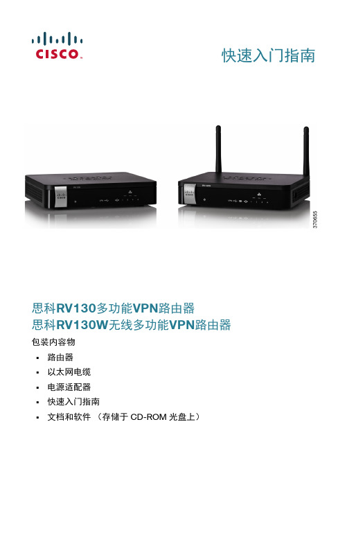
快速入门指南思科RV130多功能VPN路由器思科RV130W无线多功能VPN路由器包装内容物•路由器•以太网电缆•电源适配器•快速入门指南•文档和软件(存储于 CD-ROM 光盘上)欢迎感谢您选择思科RV130/RV130W路由器。
本指南介绍了如何安装思科 RV130/RV130W并启动基于Web的设备管理器。
安装思科 RV130/RV130W1安放提示为防止设备过热或者受损:•环境温度 — 请勿在环境温度超过 40°C (104°F)的区域中使用。
•通风 — 请确保设备周围的通风良好。
•机械负载 — 请确保设备放置平稳,以免出现任何对设备造成损坏的情况。
请将设备放置在水平的表面上,以便设备依靠四个橡胶支脚来支撑。
壁挂式安装路由器的底部面板上有两个壁挂槽。
要将路由器安装到墙上,您需要安装硬件(未随机附赠)。
建议的木螺丝尺寸如图所示(非真实比例)。
2思科RV130/RV130W多功能VPN路由器思科RV130/RV130W 多功能VPN 路由器 3思科 RV130/RV130W 的特性RV130前面板电源当设备开启电源并启动时,指示灯呈绿色常亮状态。
设备正在启动或升级固件时,指示灯呈绿色闪烁状态。
如果设备在运行损坏的固件,指示灯会快速闪烁。
VPN (仅适用于站点到站点的 IPsec VPN )当至少有一个 VPN 隧道处于活动状态时,指示灯呈绿色常亮状态。
当通过 VPN 隧道接收或传输数据时,指示灯呈绿色闪烁状态。
当没有任何启用的 VPN 隧道处于活动状态时,指示灯呈琥珀色状态。
USB USB 装置成功连接到 Internet 服务提供商 (ISP)且 IP 地址已分配时,指示灯呈绿色常亮状态。
端口正在发送或接收数据时,指示灯呈绿色闪烁状态。
当 USB 装置已被识别但未能连接到 ISP 时,指示灯呈琥珀色状态。
WAN 当使用有线连接将设备连接至互联网后,指示灯呈绿色常亮状态。
当设备未连接到互联网或正在使用 USB 装置连接时,指示灯处于熄灭状态。
路由器的使用说明

路由器的使用说明随着互联网的普及和发展,路由器已经成为了家庭和办公场所网络连接的重要设备。
正确使用路由器可以提供稳定、快速的网络连接,方便我们进行各种网络活动。
本文将详细介绍路由器的使用方法和注意事项,帮助读者正确设置和操作路由器。
一、路由器的安装与连接1. 设备准备在正式安装路由器之前,确保你已经准备好以下设备:- 一台电脑或笔记本电脑- 一根网线- 一台路由器- 一个宽带(ADSL/Cable)连接器2. 连接和电源首先,将宽带连接器插入路由器的WAN口(也称为Internet口),然后用网线将路由器的LAN口(也称为Ethernet口)与电脑连接。
最后,将路由器插入电源并开启。
二、登录路由器管理界面1. 确定默认IP地址每个路由器的管理界面都有一个默认的IP地址,通常是192.168.1.1或者192.168.0.1。
在浏览器的地址栏中输入这个IP地址,并按下Enter键。
2. 输入用户名和密码在管理界面的登录页面上,输入默认的用户名和密码。
如果不熟悉用户名和密码,可以在路由器说明书中查找或者联系厂商获取。
三、配置路由器1. 设置WAN连接在路由器管理界面中,选择“WAN设置”或类似名称的选项。
根据提供的宽带类型(ADSL或Cable),选择相应的连接类型并填写相关信息。
根据网络服务提供商的要求,可能需要输入账号和密码。
2. 设置局域网连接选择“局域网设置”或类似名称的选项,配置路由器的局域网连接。
通常情况下,保持默认设置即可。
如果你需要连接更多设备,可以启用DHCP服务器功能以自动分配IP地址。
3. 设置无线网络(可选)如果你的路由器支持无线功能,你可以设置一个无线网络以供多个设备连接。
在管理界面中查找“无线设置”或类似选项,设置无线网络的名称(SSID)和密码。
使用WPA2加密可以提高安全性。
四、连接其他设备1. 有线连接使用网线将其他设备连接到路由器的LAN口上,可以通过有线方式获取网络连接。
戴尔高墙无线系统用户手册说明书

Owner’s ManualPAGESAFETY PRECAUTIONS2 .....................................................................................GENERAL2 .................................................................................................INDOOR UNIT PART NAMES3 ................................................................................. DISPLAY PANELS3 .......................................................................................... REMOTE CONTROL PART NAMES4............................................................................REMOTE CONTROL5 ........................................................................................ REMOTE CONTROL FUNCTIONS6.............................................................................COMBINA TION BUTTONS7 ................................................................................... CLEANING, MAINTENANCE AND TROUBLESHOOTING8........................................................NOTE TO EQUIPMENT OWNER:Please read this Owner’s Information Manual carefully before installing and using this appliance and keep this manual for future reference.For your convenience, please record the model and serial numbers of your new equipment in the spaces provided. This information, along with the installation data and dealer contact information, will be helpful should your system require maintenance or service.UNIT INFORMATIONModel # ___________________________________ Serial # ___________________________________INSTALLATION INFORMATIONDate Installed _____________________________DEALERSHIP CONTACT INFORMATION Company Name: _________________________________ Address:_________________________________________ ________________________________________________ Phone Number:__________________________________ Technician Name:_________________________________ ________________________________________________SAFETY PRECAUTIONSAny time you see this symbol in manuals, instructions and on the unit, be aware of the potential for personal injury. There are three levels of precaution:DANGER identifies the most serious hazards which will result in severe personal injury or death.WARNING signifies hazards that could result in personal injury or death.CAUTION is used to identify unsafe practices which would result in minor personal injury or product and property damage. NOTE is used to highlight suggestions which will result in enhanced installation, reliability, or operation.GENERALThe high wall fan coil unit provides quiet, maximum comfort. In addition to cooling and/or heating, the high wall fan coil unit matched with an outdoor condensing unit will filter and dehumidify the air in the room to provide maximum comfort. IMPORTANT: The high wall fan coil unit should be installed by authorized personnel only; using approved tubing and accessories. If technical assistance, service or repair is needed, contact the installer.The high wall fan coil unit can be set up and operated from the remote control (provided). If the remote is misplaced, the system can be operated from the “Auto” setting on the unit. Operating Modes:The high wall fan coil unit has five operating modes.S Fan onlyS AutoS HeatingS CoolingS Dehumidification (DRY)Fan OnlyIn Fan Only mode, the system filters and circulates room air without changing room air temperature.AutoIn Auto mode, the system will automatically cool or heat the room according to the user−selected set point.HeatingIn Heating mode, the system heats and filters room air. CoolingIn Cooling mode, the system cools, dries and filters room air. Dehumidification (DRY)In Dehumidification mode, the system dries, filters and slightly cools room air temperature. Use of this mode does not take the place of a dehumidifier.Remote ControlThe remote control transmits commands to set up and operate the system. The control has a window display panel that shows the current system status. The control can be secured to a surface when used with the mounting bracket provided.INDOOR UNIT PART NAMESPart Name1. Front Panel2.Aux. Button 3.Filter4.Rem ote Controller5.Inter-Connection Wire6. Drain Hose7.Refrigerant LinesOutdoor unit35Fig. 1 − Indoor/Outdoor UnitDISPLAY PANELSNOTE: The display panel on the indoor unit can be turned on or off using the LIGHT button on the remote control.* The temperature readout will be replaced by an error code if there is a malfunction.REMOTE CONTROL PART NAMES1ON/OFF button 2+/- button 3Cool button 4Heat button 6FOLLOW ME button 7Up down swing button 9Left right swing button14Temp button 15Sleep button Light button 1617Wifi button11Clock button 1213X-Fan button 10T-ON/T-OFF button 8Mode button5Fan button"Blank"Fig. 2 − Remote ControlRemote Control Displayheating function Fig. 3 − Remote Control DisplayNOTE: The FOLLOW ME button, formerly called the I FEEL button, possesses the same functionality. Starting on production of week 12year 2016 (serial number 1216V15000).REMOTE CONTROLNOTE: To switch between _C and _F, push the “MODE” and “−” button simultaneously while the remote controller is off.IMPORTANT: The remote control can operate the unit from a distance of up to 25 ft. (7.6 m) as long as there are no obstructions. This is one way communication only (from remote control to fan coil).The remote control can perform the following basic functions:S Turn the system ON and OFFS Select operating modeS Adjust room air temperature set point and fan speedS Adjust airflow directionBattery InstallationTwo AAA 1.5 v alkaline batteries (included) are required for operation of the remote control.To install or replace batteries:1.Slide the back cover off the control to open the batterycompartment.2.Remove old batteries if you are replacing the batteries.3.Insert batteries. Follow the polarity markings inside thebattery compartment.4.Replace battery compartment cover.A08299 Fig. 4 − Battery Compartment CoverNOTE:1.When replacing batteries, do not use old batteries or adifferent type battery. This may cause the remote control tomalfunction.2.If the remote is not going to be used for several weeks,remove the batteries. Battery leakage may damage theremote control.3.The average battery life under normal use is about 6months.4.Replace the batteries when there is no audible beep from theindoor unit or if the Transmission Indicator fails to light.REMOTE CONTROL MATCHINGThe system require the wireless remote controller to be matched to the indoor High wall unit before beginning any operations, otherwise the indoor High wall unit will not accept commands from the remote controller. Follow the instructions below to automatically match the remote controller to the indoor high wall unit:1.Turn on electrical power to the indoor and outdoor units. Theindoor high wall unit powers up in the Off (or Standby) mode.2.Hold the remote controller 5 to 6 feet from the indoor highwall unit.3.Point the remote controller at the indoor wall unit and pressthe Blank button for 3 seconds.4.The indoor high wall unit provides 3 beeps to signal asuccessful match.5.Press the Power ON button on the remote controller. Thegreen indicator light displays on the indoor high wall unit.6.The remote controller is matched and ready for use. If theindoor unit and remote controller fail to match, check theremote controller batteries, move closer and repeat thematching process again.NOTE: This is a one−time requirement only. The remote controller and indoor high wall unit need to be successfully matched only once.Remote Control Operation − Quick Start NOTE: When transmitting a command from the remote control to the unit, be sure to point the control toward the LED display on thefront panel of the unit. The unit confirms receipt of a command by sounding an audible beep.1.Turn the unit on by pushing the ON/OFF button.2.Select the desired mode by pushing the mode button.Fig. 5 − Modes3.Select the temperature set point by pointing the control towardthe unit and pressing the “+” or “−” temperature set pointbuttons until the desired temperature appears on screen.4.Select the desired fan speed by pressing the FAN SPEEDbutton to select desired fan speed.NOTE: If unit is operating in Dry mode (X−FAN), low fan speed will be displayed and the fan speed cannot be changed.5.Set the airflow direction. When the unit is turned on, thelouvers default to the cooling or heating position. The usercan adjust the default louver position by pushing the“SWING” buttons. For details on operating the SWINGlouvers, refer to the Remote Control Functions section. Emergency OperationIf the remote control is lost, damaged, or the batteries are exhausted, the ON/OFF button on the unit can be used to run the unit. Press the ON/OFF button once briefly when the system is off. To stop emergency operation, push the ON/OFF button once.Warning: Use insulated objectto press the auto buttonFig. 6 − Emergency OperationCombination of “MODE” and “−” Buttons: Switch between Fahrenheit and Centigrade. At unit OFF, press the“MODE’” and “−” buttons simultaneously to switch between _C and _F.REMOTE CONTROL FUNCTIONS The remote control is the interface between the user and the high−wall systems. Commands are entered by the user to control the system. Any command that has been entered with the remote control will remain in the memory until it is changed by the user or the batteries are replaced.the direction of the LED display on the front panel. The appears for a short period of time on the remote control when the command is entered. The unit only emits an audible beep when the signals are received correctly.ON/OFF:Press this button to turn unit on and off.MODE:Each time this button is pressed, a mode is selected in a sequence that goes from AUTO, COOL, DRY, FAN and HEAT, as shown below:Fig. 7 − ModesAUTO mode is the default setting at start−up. In AUTO mode, the set temperature will not be displayed on the LCD, and the unit automatically selects the suitable operation mode to provide comfort based on parameters set from the factory.—:Press this button once to decrease the setpoint by 1_F. If the button is pressed for more than two seconds, the setpoint decreases rapidly in increments of 1_F. In AUTO mode, set temperature is not adjustable.+:Press this button to increase the setpoint by 1_F. If the button is pressed for more than two seconds, the setpoint increases rapidly in increments of 1_F. In AUTO mode, set temperature is not adjustable. COOL:To cool to the selected set point and remove moisture.System varies compressor speed to maintain desired temperature. HEAT:To heat to selected room set point. System varies compressor speed to maintain desired room temperature.FAN:This button is used to set the fan speed in the following sequence.Fig. 8 −Fan speedPress the Vertical Swing Louver button to select five differentvertical (up and down) air discharge directions includingContinuous Sweep. The Swing Louver icon appears. Press thisbutton to set swing angle, which changes directions as shownbelow.Indicates louver swings back and forth in the five directions, as shown.1023451Fig. 9 − Swing buttons:Press the Horizontal Swing Louver button to select five differenthorizontal (left and right) air discharge directions includingContinuous Sweep. The Horizontal Swing Louver icon appears.Press this button to set swing angle, which changes in direction asshown in the following figure.Fig. 10 − Horizontal Swing Louver AnglesFOLLOW ME:Press this button to use the FOLLOW ME function, and the iconappears. The unit senses room temperature at the remote controllerinstead of at the indoor unit. It then adjusts airflow and temperatureaccordingly for the ultimate in personal comfort control and energysavings.Press the button again to exit this function. For best performance,keep remote controller away from heat or cold temperature sourceswhile using this function.TEMP:Each time this button is pressed, the display on the indoor unit isswitched in a sequence that goes from No display > SetTemperature > Indoor Ambient Temperature, as shown below.Fig. 11 − Temp ModesWhen selecting with remote controller or no display, thetemperature indicator on indoor unit displays the set temperature.When selecting with the remote controller, the temperatureindicator on indoor unit displays indoor ambient temperature; 3slater or within 3s it receives another remote controller signal thatwill return to display the setting temperature.NOTE: This model does not have an outdoor ambienttemperature function. While the remote controller can operateand the indoor unit displays the set temperature. The unitdefaults to the set temperature display when turning on theunit.X−FAN:Press the X−FAN button in COOL or DRY mode to activate theDRY function and the X−FAN icon appears. When this functionis activated, the indoor fan continues to run for 2 minutes to drythe indoor coil after the unit is turned off. X−FAN is not availablein AUTO, FAN and HEAT mode.T−ON button (Timer ON)To set when you want the unit to turn On at the end of a selectedtime period, use the button labeled “T−ON” on the remotecontroller. Press this button to make the clock icon disappear,replaced with the word “ON” (blinking). Press “+” or“−” buttonsto adjust timer setting 1 minute at a time. Press and hold “+”or “−” button to set timer more quickly. Press“T−ON” buttonagain to confirm setting, and the word “ON” stops blinking.To cancel, press“T−ON” button again.T−OFF button (Timer OFF)NOTE: Under Timer On and Off status, you can set T−ONand T−OFF simultaneously. Before setting timer, be sure toset clock to correct time.CLOCK SETTINGPress this button to set clock time. The Clock icon on remote controller blinks. Within 5 seconds, press “+” or “−” button to set clock time. With each press of the “+” or “−” buttons, the clock time increases or decreases by 1 minute. To quickly adjust the time setting, press and hold “+” or “−” button for 2 seconds. Release the button when you have reached the desired time setting. Press the “CLOCK” button to confirm the time, and clock icon stops blinking.NOTE: Clock time adopts 24−hour mode. A 12−hour format is not available.SLEEP MODE:The unit automatically adjusts room temperature during your sleep time. This slight change in temperature will not affect your comfort level due to the natural effects that sleeping has on the body, however it saves on energy consumption and lowers your electric bill.The unit has four Sleep Modes to select from. Press the SLEEP button to select Sleep 1, Sleep 2, Sleep 3, Sleep 4 modes or Cancel. The SLEEP icon appears.TRADITIONAL MODE − SLEEP 1In Traditional Mode the unit slowly relaxes the room set temperature by up to 4_F until Sleep Mode is cancelled.Cooling Mode Heating ModeFig. 12 − Cooling and Heating ModesEXPERT MODE − SLEEP 2In Expert Mode the unit adjusts the room set temperature at a rate based on the starting set temperature value. Sleep Mode continues until cancelled.Cooling Mode Heating ModeFig. 13 − Cooling and Heating ModesDIY MODE SLEEP 3You are required to enter eight (8) room set point values for eight (8) hours of run time. The last room set point value is maintained until the sleep mode is cancelled.In Sleep Mode 3, press the “Prog” button to enter the setup mode. The remote controller displays “1:00” in the time location. Use the “+”and “−” buttons to select the desired room set point for the first hour of run time. Then press the “Prog” button to save the set point.Repeat this sequence for the eight (8) room set point values. After all eight (8) values have been entered, the remote controller automatically reverts to standard time and temperature display, and the Sleep 3 Mode starts.At any time, you may press the “ON/OFF,” “Mode,” “Timer,”“Sleep” or “Turbo” buttons to cancel the Sleep 3 Mode. NOTE: During this procedure, if no button is pressed within 10 seconds, the remote controller automatically exits the sleep curve setting and resumes the original display. If the ON/OFF, MODE, TIMER, SLEEP, COOLING or HEATING button is pressed during the setting or inquiry procedure, the remote controller exits the sleep curve setting.SIESTA MODE 4:In Siesta Mode the unit automatically changes the room temperature every 30 minutes based on the room temperature setting. The Sleep Mode continues until cancelled.Cooling Mode Heating ModeFig. 14 − Siesta ModeNOTE: Sleep function can not be set in AUTO mode. LIGHT:This function allows the user to turn the display ON or OFF on the front panel.Press the light icon to turn the indoor unit front panel ON or OFF. The remote control displays the Light Icon .WIFI Button:Press and hold this button for three seconds to turn WIFI function on or off. See the “Operation of Smart Control” section for more information.Only the set point temperature appears on the front panel and on the remote controller.COMBINATION BUTTONS Combination of “+” and “−” Buttons:Press “+” and “−the remote controller.46_F Heating Functions:Under the heating mode, press the “TEMP” and “CLOCK” buttons simultaneously to start the 46_F heating function. When this function starts, the “$” and 46_F icons appear on the remote controller, and the air conditioner maintains the heating status. Press the “TEMP” and “CLOCK” buttons simultaneously again to exit the 46_F heating function.NOTE: Under the 46_F heating function, the fan speed defaults to the auto speed and it can not be adjusted.Under the 46_F heating function, the set temperature cannot be adjusted. Press the TURBO button and the remote controller will not send the signal. The Sleep function and the 46_F heating function can not operate at the same time. If the 46_F heating function has been set under the Cooling mode, press the Sleep button to cancel the 46_F heating function. If the Sleep function was set under the Cooling mode, the 46_F heating function cancels the Sleep function.CLEANING, MAINTENANCE AND TROUBLESHOOTINGPeriodic MaintenancePeriodic maintenance is recommended to ensure proper operation of the unit. Recommended maintenance intervals may vary depending on the installation environment, e.g., dusty zones, etc.Refer to Table 1.Cleaning the CoilClean the coil at the beginning of each cooling season, or when necessary . Use a vacuum cleaner or a long −bristle brush to avoid damage to the coil fins.Air FiltersRemove and clean the air filters once a month.NOTE: If air filters show signs of excessive wear or are torn, they must be replaced. Contact your local dealer for replacement filters.1.Open front panel on unit.2.Pull filters down to remove.3.Vacuum filters.4.Clean with warm water.5.Shake filter to remove excess water and dry thoroughly.6.Replace filter by sliding into rack until filter snaps in place.7.Close front panel on unit.Indoor Unit Front PanelTo clean the front panel on the indoor unit, wipe the outside with a soft, dry cloth. If necessary, a mild liquid detergent can be applied and wiped off with a dry cloth.Preparing for Extended Shutdown PeriodClean the filters and reposition them in the unit. Operate the unit in Fan only mode for 12 hours to dry all internal parts.Turn main power supply off and remove batteries from the remote control.System Operation RecommendationsThe items outlined in the following list helps to assure proper system operation:S Replace both remote control batteries at the same time.S Point the remote control toward the unit display panel when transmitting a command.S Keep doors and windows closed while unit is operating.S Contact an authorized service representative if a problem arises that cannot be easily resolved.S Do not perform cleaning or maintenance activities while unit is on.S Keep display panel on unit away from direct sunlight and heat as this may interfere with remote control transmissions.S Do not block air intakes and outlets on the indoor or outdoor units.Energy Saving RecommendationsThe following recommendations add greater efficiency to the ductfree system:S Select a comfortable thermostat setting and leave it at chosen setting. Avoid continually raising and lowering the setting.S Keep unit filter clean. Frequent cleaning may be necessary depending on indoor air quality.S Use drapes, curtains or shades to keep direct sunlight from heating room on very hot days.S Do not obstruct air intake on front panel.S Turn on air conditioning before indoor air becomes too uncomfortable.TroubleshootingRefer to Table 2 before contacting your local dealer.Table 1—Periodic Maintenance{Maintenance to be carried out by qualified service personnel. Refer to the Installation ManualTable 2—TroubleshootingManufacturer reserves the right to discontinue, or change at any time, specifications or designs without notice and without incurring obligations.E 2016 Bryant Heating & Cooling Systems D 7310 W. Morris St. D Indianapolis, IN 46231 Edition Date: 03/16Replaces: NEWCatalog No. OM-619FB-01。
路由器 说明书
第1章安装指南首先,非常感谢您购买本公司的产品。
这本使用手册将会介绍您如何安装和使用本产品的强大功能。
针对首次使用本产品的用户,请按照本安装指南的指示完成基本的安装和设置。
而对熟悉本产品安装与使用的用户,请直接参阅相应的部分章节。
1.1 硬件安装(略)建立正确的网络设置路由器默认ip 地址是192.168.1.1,默认子网掩码是255.255.255.0。
这些值可以根据您的实际需要而改变,但本用户手册上将按默认值说明。
首先请将您的计算机接到路由器的局域网端口,接下来您可以使用两种方法为您的计算机设置ip 地址。
方法一:手动设置ip 地址。
设置您计算机的tcp/ip 协议。
如果您已经正确设置完成,请跳过第一步。
设置您计算机的ip 地址为192.168.1.xxx(xxx 范围是2 至254),子网掩码为255. 255.255.0,默认网关为192.168.1.1,首选DNS服务器为192.168.1.1。
方法二:利用路由器内置dhcp 服务器自动设置ip 地址。
1) 设置您计算机的tcp/ip 协议为“自动获取ip 地址”。
2) 关闭路由器和您的计算机电源。
3) 打开路由器电源,然后再启动您的计算机。
4) 这样路由器内置dhcp 服务器将自动为您的计算机设置ip 地址。
在设置好tcp/ip 协议后,您可以使用ping 命令检查您的计算机和路由器之间是否联通。
下面的例子为一个在windows xp 环境中,执行ping 命令,操作步骤如下: 首先请您点击桌面的“开始”菜单,再选择“运行”选项,并在随后出现的运行输入框内输入cmd 命令,然后回车或点击“确认”键即可进入下图所示界面。
最后在该界面中输入命令ping 192.168.1.1,其结果显示如下。
如果屏幕显示为:那么恭喜您!您的计算机已与路由器成功建立连接。
如果屏幕显示为:这说明设备还未安装好,您可以按照下列顺序检查:1) 硬件连接是否正确?路由器面板上对应局域网端口的link/act 指示灯和您计算机上的网卡灯必需亮。