以太网远程控制开关量模块使用说明书样本
莫克8口无管理以太网开关产品说明书
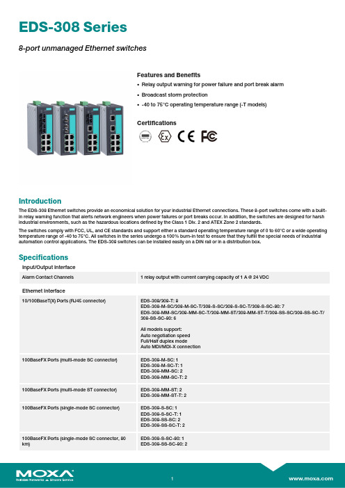
EDS-308Series8-port unmanaged Ethernet switchesFeatures and Benefits•Relay output warning for power failure and port break alarm •Broadcast storm protection•-40to 75°C operating temperature range (-T models)CertificationsIntroductionThe EDS-308Ethernet switches provide an economical solution for your industrial Ethernet connections.These 8-port switches come with a built-in relay warning function that alerts network engineers when power failures or port breaks occur.In addition,the switches are designed for harsh industrial environments,such as the hazardous locations defined by the Class 1Div.2and ATEX Zone 2standards.The switches comply with FCC,UL,and CE standards and support either a standard operating temperature range of 0to 60°C or a wide operating temperature range of -40to 75°C.All switches in the series undergo a 100%burn-in test to ensure that they fulfill the special needs of industrial automation control applications.The EDS-308switches can be installed easily on a DIN rail or in a distribution box.SpecificationsInput/Output InterfaceAlarm Contact Channels1relay output with current carrying capacity of 1A @24VDCEthernet Interface10/100BaseT(X)Ports (RJ45connector)EDS-308/308-T:8EDS-308-M-SC/308-M-SC-T/308-S-SC/308-S-SC-T/308-S-SC-80:7EDS-308-MM-SC/308-MM-SC-T/308-MM-ST/308-MM-ST-T/308-SS-SC/308-SS-SC-T/308-SS-SC-80:6All models support:Auto negotiation speed Full/Half duplex modeAuto MDI/MDI-X connection100BaseFX Ports (multi-mode SC connector)EDS-308-M-SC:1EDS-308-M-SC-T:1EDS-308-MM-SC:2EDS-308-MM-SC-T:2100BaseFX Ports (multi-mode ST connector)EDS-308-MM-ST:2EDS-308-MM-ST-T:2100BaseFX Ports (single-mode SC connector)EDS-308-S-SC:1EDS-308-S-SC-T:1EDS-308-SS-SC:2EDS-308-SS-SC-T:2100BaseFX Ports (single-mode SC connector,80km)EDS-308-S-SC-80:1EDS-308-SS-SC-80:2Standards IEEE802.3for10BaseTIEEE802.3u for100BaseT(X)and100BaseFXIEEE802.3x for flow controlOptical Fiber800Typical Distance4km5km40km80kmWavelen-gthTypical(nm)130013101550TX Range(nm)1260to13601280to13401530to1570 RX Range(nm)1100to16001100to16001100to1600Optical PowerTX Range(dBm)-10to-200to-50to-5 RX Range(dBm)-3to-32-3to-34-3to-34 Link Budget(dB)122929 Dispersion Penalty(dB)311Note:When connecting a single-mode fiber transceiver,we recommend using anattenuator to prevent damage caused by excessive optical power.Note:Compute the“typical distance”of a specific fiber transceiver as follows:Linkbudget(dB)>dispersion penalty(dB)+total link loss(dB).DIP Switch ConfigurationEthernet Interface Port break alarmSwitch PropertiesMAC Table Size2kbitsPacket Buffer Size768KProcessing Type Store and ForwardPower ParametersInput Current EDS-308/308-T:0.07A@24VDCEDS-308-M-SC/S-SC Series,308-S-SC-80:0.12A@24VDCEDS-308-MM-SC/MM-ST/SS-SC Series,308-SS-SC-80:0.15A@24VDC Connection1removable6-contact terminal block(s)Operating Voltage9.6to60VDCInput Voltage Redundant dual inputs,12/24/48VDCReverse Polarity Protection SupportedOverload Current Protection SupportedPhysical CharacteristicsHousing MetalIP Rating IP30Dimensions53.6x135x105mm(2.11x5.31x4.13in)Weight790g(1.75lb)Installation DIN-rail mounting,Wall mounting(with optional kit) Environmental LimitsOperating Temperature Standard Models:-10to60°C(14to140°F)Wide Temp.Models:-40to75°C(-40to167°F) Storage Temperature(package included)-40to85°C(-40to185°F)Ambient Relative Humidity5to95%(non-condensing)Standards and CertificationsHazardous Locations ATEX,Class I Division2EMI CISPR32,FCC Part15B Class AMaritime DNV-GLEMC EN55032/24Vibration IEC60068-2-6EMS IEC61000-4-2ESD:Contact:6kV;Air:8kVIEC61000-4-3RS:80MHz to1MHz:20V/mIEC61000-4-4EFT:Power:2kV;Signal:1kVIEC61000-4-5Surge:Power:2kV;Signal:2kVIEC61000-4-6CS:10VIEC61000-4-8PFMFSafety UL508,UL60950-1,CSA C22.2No.60950-1 Shock IEC60068-2-27Freefall IEC60068-2-32MTBFTime255,528hrsStandards MIL-HDBK-217FWarrantyWarranty Period5yearsDetails See /warrantyPackage ContentsDevice1x EDS-308Series switchInstallation Kit1x cap,plastic,for SC fiber port2x cap,plastic,for SC fiber port(-SC models)2x cap,plastic,for ST fiber port(-ST models) Documentation1x quick installation guide1x warranty cardDimensionsOrdering InformationModel Name 10/100BaseT(X)PortsRJ45Connector100BaseFX PortsMulti-Mode,SCConnector100BaseFX PortsMulti-Mode,STConnector100BaseFX PortsSingle-Mode,SCConnectorOperating Temp.EDS-3088–––0to60°CEDS-308-T8–––-40to75°C EDS-308-M-SC71––0to60°CEDS-308-M-SC-T71––-40to75°C EDS-308-MM-SC62––0to60°CEDS-308-MM-SC-T62––-40to75°C EDS-308-MM-ST6–2–0to60°CEDS-308-MM-ST-T6–2–-40to75°C EDS-308-S-SC7––10to60°CEDS-308-S-SC-T7––1-40to75°C EDS-308-SS-SC6––20to60°CEDS-308-SS-SC-T6––2-40to75°C EDS-308-S-SC-807––10to60°CEDS-308-SS-SC-806––20to60°C Accessories(sold separately)Power SuppliesDR-120-24120W/2.5A DIN-rail24VDC power supply with universal88to132VAC or176to264VAC input byswitch,or248to370VDC input,-10to60°C operating temperatureDR-452445W/2A DIN-rail24VDC power supply with universal85to264VAC or120to370VDC input,-10to50°C operating temperatureDR-75-2475W/3.2A DIN-rail24VDC power supply with universal85to264VAC or120to370VDC input,-10to60°C operating temperatureMDR-40-24DIN-rail24VDC power supply with40W/1.7A,85to264VAC,or120to370VDC input,-20to70°Coperating temperatureMDR-60-24DIN-rail24VDC power supply with60W/2.5A,85to264VAC,or120to370VDC input,-20to70°Coperating temperatureWall-Mounting KitsWK-46Wall-mounting kit,2plates,8screws,46.5x66.8x1mmRack-Mounting KitsRK-4U19-inch rack-mounting kit©Moxa Inc.All rights reserved.Updated Jan30,2019.This document and any portion thereof may not be reproduced or used in any manner whatsoever without the express written permission of Moxa Inc.Product specifications subject to change without notice.Visit our website for the most up-to-date product information.。
ControlM使用手册
Control-M使用手册中亦安图科技发展(北京)有限公司二零一二年十二月1体系结构1.1架构说明CONTROL-M生产管理建立在一个三层结构基础上,它包括CONTROL-M/Enterprise Manager,CONTROL-M/Server和CONTROL-M/Agents 三个组件。
CONTROL-M/Enterprise Manager(以下简称:CONTROL-M /EM)提供一个统一的,适用于所有平台的GUI界面。
它拥有自己的独立的数据库,通过Gateway与Control-M/Server进行连接,管理与控制所有的Control-M/Server与Control-M/Agent。
Control-M的服务器(Server)Control-M 处理的核心,它是调度作业、管理作业处理流程、提供作业流状态信息的引擎。
保存所有作业的定义及其调度规则。
同一架构体系中Control-M/Server可以有多个(青岛银行目前只有一个)。
Control-M/Agent负责在应用服务器上执行具体的作业,如批量调度,文件传输等等。
Control-M/Agent可安装在各种操作系统上,并提供如AFT(文件传输),DATABASES(数据库存储过程),SAP(SAP软件相关)等功能模块方便不同的应用进行作业执行。
注:另外在CONTROL-M/Server和CONTROL-M/EM Server支持高可用,保障整个系统的不受故障影响。
作业生命周期:1.作业在Control-M/EM提供的GUI界面中进行定义。
2.作业提交到Control-M/Server进行调度。
3.Control-M/Server将作业提交到所需执行的Control-M/Agent进行执行。
4.Control-M/Agent将作业执行信息返回到Control-M/Server。
5.Control-M/Server将作业信息同步到Control-M/EM供GUI界面进行展示。
Sophos SD-RED 20 SD-RED 60 远程以太网设备操作说明书
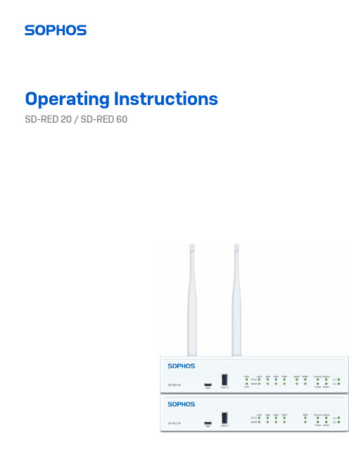
Operating Instructions SD-RED 20 / SD-RED 60ForewordWe are pleased to welcome you as a new Sophos SD-RED customer.Sophos SD-RED (Remote Ethernet Device) is the ideal solution to easily extend your secure network beyond your main facility to branch offices, retail outlets, and other remote locations.SD-RED devices are built on the latest enterprise-class, high-speed networking platforms, providing state-of-the art data encryption technology to securely transport your data over the internet.All configuration and management is done on a Sophos Firewall located at your main facility and requires no technical skills at the remote site.These operating instructions will help you install and configure the Sophos SD-RED device and provide technical specifications of all SD-RED models. In addition, please also see the following documents:ÌHardware Quick Start Guide: Connection to the system peripherals in a few stepsÌSafety Instructions: Notes on safety regulations and regulatory complianceÌSophos Firewall Administration Guides: Configuring your SD-REDappliance within the central Sophos SG UTM or XG Firewall applianceThe Hardware Quick Start Guide and the Safety Instructions are also delivered in printed form together with the hardware appliance. The instructions should be read carefully prior to using the device and should be kept in a safe place.You may download all user manuals and additional documentation from the support webpage at /support and from /get-started-sd-red. Security SymbolsThe following symbol and its meaning appears in the Hardware Quick Start Guide, Safety Instructions and in these Operating Instructions.Caution and Important Note. If these notes are not correctly observed:ÌThis is dangerous to life and the environmentÌThe device may be damagedÌThe functions of the device will be no longer guaranteedÌSophos shall not be liable for damages arising from afailure to comply with the Safety InstructionsDesigned UseSD-RED devices are developed for use in networks. They can only be operated in conjunction with a central Sophos Firewall but not as a standalone appliance. The hardware device can be used in commercial, industrial, and residential environments.SD-RED models belong to the appliance group B.The hardware appliance must be installed pursuant to the current installation notes. Otherwise failure-free and safe operation cannot be guaranteed. The EU declaration of conformity is available from the following address:Sophos Technology GmbHGustav-Stresemann-Ring 165189 WiesbadenGermanyCE Labeling, FCC and Approvals The SD-RED appliances comply with CB, CE, FCC, ISED/ICES, VCCI, RCM, UL, CCC, KC, Anatel.Important note: For computer systems to remain CE and FCC compliant, only CE and FCC compliant parts may be used. Maintaining CE and FCC compliance also requires proper cable and cabling techniques.Operating Elements and Connections SD-RED 20 / SD-RED 60*PoE LEDs (SD-RED 60 only)Status LEDs Power LEDs USB 3.0Port LEDs Micro-USBCOM port GbE WAN (WAN2 on SD-RED 60 only)Expansion Bay for optional Wi-Fi or 3G/4G module SFP 2 x Power supply 4 x GbE LAN USB 3.0* The displayed images is of the SD-RED 60 device. The SD-RED 20 device may vary slightly.Interfaces (front)Power and Port LEDsStatus LEDs* This LED pattern will only be seen once the tunnel is established.* The blinking behavior is an on/off cycle approx. once every 1.3 seconds. ** The blinking behavior is an on/off cycle approx. once every 2.5 seconds.Installation Preliminary steps Make sure that the SD-RED device has been shipped to the branch office/remote location. Ask the person who is going to put the SD-RED appliance into operation at the branch office to provide the unique SD-RED ID, which is printed on the bottom of the device. Note that the SD-RED device requires a working internet connection at your branch office.Configuring the SD-RED device Configure the SD-RED device in your central SG UTM or XG Firewall as described in the respective Sophos Firewall Administration Guides. After completion, the configuration will be uploaded to the cloud-based Sophos broker service.Connecting the SD-RED at the remote site Connect the SD-RED device to your router or cable at the remote site as described within the Quick Start Guide and power it on.After the system has booted, it will connect to the internet to retrieve its configuration from the Sophos broker service.The status LEDs “System,” “Router,” “Internet,” “Tunnel” should then turn on one after the other.If you don’t see all four status LEDs turned on or the “System” LED is blinking red, please refer to the LED table above to identify possible error states and contact your administrator.Important note: If all four status LEDs are blinking in a rotatory sequence the device is installing a new firmware version.DO NOT POWER IT OFF. The device will reboot automatically.Powering off the device at this stage could render it inoperable and require its return to the reseller.Connecting PoE power devices to a SD-RED 60On SD-RED 60 models, Ports LAN1 and LAN3 are able to provide power over ethernet (PoE) to a connected PoE device which conforms to the standards 802.3af (max. 15.4W) or 802.3at (max. 30W). Each port can provide up to 30 watts max. However, if PoE power is provided to both ports concurrently then the total power drawn should not exceed 30 watts. You can connect either one 802.3at or two 802.3af devices at the same time asshown below:Please consult the documentation of your PoE powered device to identify its correct power class.Important note: If you accidentally connect one 802.3at and one other 802.3at or 802.3af device at the same time, power for the device on LAN3 (lower priority) will be disabled and the connected device will lose power. The PoE LED of this port will start blinking, indicating a PoE power error, until you remove one of the devices from the LAN1 or LAN3 port (please also see PoE LED table above).Tunnel Router Internet System Tunnel Router Internet SystemTunnel RouterInternet SystemAdding an optional 3G/4G or Wi-Fi expansion moduleBoth SD-RED models have an expansion bay at the back allowing you to add either a Sophos 3G/4G or a Wi-Fi module, which are available from your Sophos partner.Both modules are shipped with two antennas (for 3G/4G or 802.11 ac 2x2 Wi-Fi). The wireless module allows you to connect wireless devices to your local LAN at the remote site.The 3G/4G module can be used as an alternative mobile WAN connection.For installation instructions, please refer to the documentation available at www.sophos. com/get-started-sd-red.Connecting devices to the SFP portBoth SD-RED models provide an SFP port which can be used to connect the unit to the local router/cable modem or other set-top box via fiber or other standard SFP mini-GBICs (transceivers).This port is a combo port shared with the WAN1 port. Therefore, you can only use one of these ports at any time.If cables are connected to both ports, the SFP port will take precedence.Using redundant power suppliesBoth SD-RED models are shipped with a single power supply, but provide a connectorto add a second redundant power supply, allowing you to keep your appliance up and running even if one power supply fails.The power LED for the respective power supply on the front of the device will only be activated once you have connected a second power supply for the first time, i.e. it will turn red in case the connected power supply fails or there is no power supply connected to the second connector at all.Serial consoleYou can connect a serial console to the Micro-USB COM port of the SD-RED devices. You can use, for instance, the HyperTerminal terminal program which is included with most versions of Microsoft Windows to log on to the appliance console. Use a Micro-USB to USB-A adapter cable to connect the console to your SD-RED device.The required connection settings are:ÌBits per second: 115,200ÌData bits: 8ÌParity: N (none)ÌStop bits: 1ÌFlow Control: N (none)Access via the serial console is activated by default on ttyS1. The connections of the appliances and the respective functionality are listed in the chapter “Operating Elements and Connections.”Mounting InstructionsThere are various options available allowing you to hang your SD-RED appliance onthe wall or mount it to a DIN Rail or into a rack. The following sections provide detailed instructions for the various options.Warnings and PrecautionsThe appliance can be operated safely if you observe the following notes and the notes on the appliance itself.Rack PrecautionsÌEnsure that the leveling jacks on the bottom of the rack are fully extendedto the floor with the full weight of the rack resting on them.ÌIn a single rack installation, stabilizers should be attached to the rack.ÌIn multiple rack installations, the racks should be coupled together.ÌAlways make sure the rack is stable before extending a component from the rack.ÌYou should extend only one component at a time – extending two ormore simultaneously may cause the rack to become unstable.General Server PrecautionsÌReview the electrical and general safety precautions that camewith the components you are adding to your appliance.ÌDetermine the placement of each component in the rack before you install the rails.ÌInstall the heaviest server components on the bottomof the rack first, and then work up.ÌAllow the hot plug hard drives and power supplymodules to cool before touching them.ÌAlways keep the rack‘s front door, all panels and server componentsclosed when not servicing to maintain proper cooling.Rack Mounting ConsiderationsÌAmbient operating temperature: If installed in a closed or multi-unit rackassembly, the ambient operating temperature of the rack environmentmay be greater than the ambient temperature of the room. Therefore,you should install the equipment in an environment compatible withthe manufacturer’s maximum rated ambient temperature.ÌReduced airflow: Equipment should be mounted into arack with sufficient airflow to allow cooling.ÌMechanical loading: Equipment should be mounted into a rack so that ahazardous condition does not arise due to uneven mechanical loading.ÌCircuit overloading: Consideration should be given to the connectionof the equipment to the power supply circuitry and the effect that anypossible overloading of circuits might have on overcurrent protectionand power supply wiring. Appropriate consideration of equipmentnameplate ratings should be used when addressing this concern.ÌReliable ground: Reliable grounding must be maintained at all times.To ensure this, the rack itself should be grounded. Particular attentionshould be given to power supply connections other than the directconnections to the branch circuit (i.e., the use of power strips, etc.).Wall mountYou can either hang the unit on the wall by using the wall mount keyholes on the rear of the unit or by using the rackmount kit which is available as an optional accessory.The following procedure explains how to use the keyholes.Please note: For wall mounting we recommend using wall plugs and screws with dimensions shown below:1. Use the wall mount template (next page) to mark thescrew mounting positions on the wall.2. Drill two wall anchors into the wall at the marked positions and screwtwo screws into them. Make sure they stand out 4-8mm. We recommendusing wall plugs and screws with the dimensions shown below.3.Hang the SD-RED unit on the wall by aligning the key holes with the mounted screws.WallTopSD-RED Wall mount template Do not shrink to fit when printingRackmountTo mount the SD-RED appliance to a rack (1U), you need the model specific rackmounting kit, which is available as an option from your Sophos partner.Please note: There are two different rackmounting kits available. Both kits fit with both models. However, only the SD-RED 60 specific kit provides additional bracket(s) to hold the desktop-type power adapter(s). These are not included with the SD-RED 20 specific kit since this model uses wall mount type power adapters which are directly plugged into the wall outlet or power strip.Make sure you only use the screws supplied with the rackmount ears. Using the wrong screws could damage the hardware appliance and would invalidate your warranty.In addition to the rackmounting kit contents, you will need a long-handed Phillips-head screwdriver.SD-RED 60 mounting instructions1. Remove existing screws from the chassisRemove the three screws from each side of the chassis.2. Install the rackmounting kit device holder to the chassisPlease note: You can mount the unit into a rack either with the front or with the back side facing to you (see figures below). Secure one device holder to each side of the appliance using three of the screws included with the box.3. Install the adapter bracketAttach the power adapter bracket either to the left or right side of the rackmounting kit by using four of the supplied screws. If you are using redundant power supplies fix the second adapter bracket on the other side.4. Install the power adapterPlace the adapter(s) on the bracket(s)The PADs supplied with the rackmount kit are only needed with SG 105/115 appliance models which use smaller power adapters (4a).For SD-RED 60 models a PAD is not required (4b).5. Install the unitYou can either install the unit into a rack (5a) or you can hang the unit on a wall (5b).Use appropriate screws (not supplied with this kit) for this purpose.For wall mount installation we recommend using wall plugs and screws withdimensions shown below (5c).5b. Wallmount installation5a. Rackmount installation5c.SD-RED 20 mounting instructionsThe required connection settings are:1. Remove existing screws from the chassisRemove the three screws from each side of the chassis.2. Install the rackmounting kit device holder to the chassisPlease note: You can mount the unit either with the front or with the back side facing to you (see figures below).Secure one device holder to each side of the appliance using three flat head M3 screws from the scope of supply.The device holders must only be fixed to the appliance by means of the supplied screws. Screws with other dimensions might damage the appliance.3. Install the unit3b. Wallmount installation3a. Rackmount installation3c.DIN Rail MountThe DIN rail mounting kit is available as an option from your Sophos partner.It includes:6 flat head M3 screws2 DIN rail mounting adapter 1. Install the mounting adapters to the chassisPlace one adapter on each side at the bottom of the chassis and secure it using three of the supplied screws.2. Mount the chassis to the DIN railHold the chassis to the DIN Rail and hang it with the fixed parts of the adapters on one side of the DIN Rail. Push the chassis towards the DIN Rail until the flexible part of the adapters snaps into the DIN Rail.Make sure the chassis is securely fixed.3. Removing the chassis from the DIN railTo remove the chassis from the rail just pull it back on the flexible side of the adapters.2.1.3.Operating Instructions SD-RED 20 / SD-RED 60© Copyright 2020-22. Sophos Ltd. All rights reserved.United Kingdom and Worldwide Sales Tel: +44 (0)8447 671131Email: ****************North American Sales Toll Free: 1-866-866-2802Email: ******************Australia and New Zealand Sales Tel: +61 2 9409 9100Email: ****************.au Asia Sales Tel: +65 62244168Email: ********************。
AELTA RTU-EN01 Modbus TCP 远程 I O 通讯模块 说明书

RTU-EN01Modbus TCP远程I/O通讯模块操作手册DVP-0213910-01Modbus TCP 远程I/O 通讯模块 RTU-EN01DVP-PLC操作手册 1注意事项3 此操作手册提供功能规格、安装、基本操作与设定内容的介绍。
3 本机为开放型 (OPEN TYPE) 机壳,因此使用者使用本机时,必须将其安装于具防尘、防潮及免于电击/冲击意外的外壳配线箱内。
另必须具备保护措施 (如:特殊的工具或钥匙才可打开) ,防止非维护人员操作或意外冲击本体,造成危险及损坏,且请勿在上电时触摸任何端子。
3 请务必仔细阅读使用手册,并依照手册指示进行操作,以免造成产品受损,或导致人员受伤。
目录1 RTU-EN01简介 (3)1.1功能介绍......................................................................................................................................3 1.2功能规格......................................................................................................................................3 2 产品外观及各部介绍 (5)2.1外观尺寸......................................................................................................................................5 2.2各部介绍......................................................................................................................................5 2.3指示灯说明..................................................................................................................................6 2.4RUN/STOP 开关..........................................................................................................................6 2.5RJ-45接脚定义...........................................................................................................................6 2.6RS-232接脚定义.........................................................................................................................6 2.7 RS-485接脚定义. (6)3 安装及配线 (7)3.1安装RTU-EN01与Slim I/O 模块................................................................................................7 3.2安装RTU-EN01及其Slim I/O 模块于导轨..................................................................................7 3.3 连接网络.. (7)4 RTU-EN01寄存器与继电器 (8)4.1基本寄存器BR (Basic Register)一览表.......................................................................................8 4.2控制寄存器BR 内容说明.............................................................................................................9 4.3外部输入继电器RX...................................................................................................................12 4.4外部输出继电器RY...................................................................................................................12 4.5I/O 模块控制寄存器RCR...........................................................................................................13 4.6定时器(Timer) – T 字节装置(WORD)与有效位(BIT)..................................................................13 4.7计数器(Counter) – C 字节装置(WORD)与有效位(BIT)..............................................................14 4.8 万年历R (BIT) (15)5 MODBUS 通讯标准 (15)Modbus TCP 远程I/O 通讯模块 RTU-EN01DVP-PLC 操作手册2 5.1支持的Function Code...............................................................................................................15 5.2支持的Exception Code.............................................................................................................16 5.3组件类型及组件地址.................................................................................................................16 6 软件设定 (16)6.1DCISoft 通讯设定及搜寻通讯模块.............................................................................................16 6.2记录IP 地址..............................................................................................................................19 6.3基本设定...................................................................................................................................19 6.4网络设定...................................................................................................................................21 6.5时间设定功能............................................................................................................................23 6.6IP 过滤......................................................................................................................................24 6.7Smart PLC 设定 – IF-THEN.....................................................................................................24 6.8Smart PLC 设定 – 定时器........................................................................................................25 6.9 Smart PLC 设定 – 计数器.. (26)6.10 Smart PLC 设定 – 万年历 (27)6.11 模拟量输入/输出模块 (28)6.12 I/O 监视功能设定表 (30)6.13 Gateway 功能设定表 (31)6.14 虚拟串行端口 (34)6.15 安全设定 (36)6.16 回归出厂设定值 (37)6.17 Web 功能 (38)7 应用范例 – DCISOFT (43)7.1Smart PLC – IF-THEN..............................................................................................................43 7.2Smart PLC – 定时器................................................................................................................45 7.3Smart PLC – 计数器................................................................................................................46 7.4Smart PLC – 万年历................................................................................................................47 7.5 虚拟串行端口应用 (48)Microsoft® 和 Windows Internet Explorer® 为 Microsoft Corporation 于美国与其它国家的注册商标或商标。
kyl-808开关量无线传输模块说明书

KYL-808开关量传输模块说明书电话:400-860-5038电话:400-860-5038一、功能描述八路开关量无线实时传送,接收模块的继电器输出与发射模块的开关输入实时关联,即发射模块输入开关闭合,接收模块相对应的输出继电器同步闭合,发射模块输入开关断开,接收模块的相对应输出继电器同步断开,各个通道互相独立。
用户无需编程,无需现场布线就可以达到远程控制的目的。
广泛应用于工业遥控器、工业现场监控、水厂自动化等项目。
图一:开关量对应关系示意图二、性能指标特性范围典型值备注电源12-30V 24V 输出电流≥500mA传输距离1-3公里-空旷视距输出数-8个输出-输出类型-继电器最大负载能力DC220V5A输入数-8个输入-输入类型I -无源触点-输入类型IIDC 0-24V低电平<1V 低电平对应闭合高电平>4.5V高电平对应断开发射电流-300mA -接收电流-30mA-尺寸-145mm*90mm*40mm-三、KYL-808端子和硬件介绍电话:400-860-5038图二:COM1-开关输出及电源接线端子1、八路继电器输出,带负载能力达220V/5A ,两个相同的Ox (x=1,2,3,4,5,6,7,8)代表一组继电器的两个触点。
图三:COM2-开关输入端子2、八路开关输入,支持无源及有源输入。
无源输入时,只需在Ix (x=1,2,3,4,5,6,7,8)及GND 之间接入一个开关或者按钮,开或者断的状态将被发送到远端输出模块,并被输出。
有源输入时,用户需在Ix (x=1,2,3,4,5,6,7,8)端子输入一个高或低电平,高电平对应断开,低电平对应闭合。
注意无电平输入时,接收端输出断开。
四、指示灯定义1、电源指示灯-PWR :上电常亮2、运行指示灯-RUN :模块每进行数据发射/接收时,指示灯闪烁3、数据指示灯-T/R :每秒闪动一次,表示模块运行正常4-11:开关输出状态指示D1-D4:指示灯亮,表示相应的输出通道闭合,反之断开五、拔码开关定义图四、拔码开关开关8发送模式选择设置描述定时模式1定时模式下一台主机,另一台须设从机电平变化触发0开关7主从模式选择设置描述主机1只在定时模式下有效,从机收到主机信息后发送应答信息从机0开关6采集模式设置描述使能1采集模式时,模块作为一台无线Modbus从机,中继/反馈、主从、发送模式均无效禁止0开关5中继/反馈传输方式设置描述使能1反馈方式时,发射机可以监控接收机输出结果禁止0拔码位置信道号拔码位置信道号拔码位置信道号拔码位置信道号15913261014371115481216*为避免同一遥控范围有两套以上遥控系统同时工作时发生冲突,不同系统的模块应选用不同信道(工作频率)*定时模式下,必须一台是主机,一台是从机*拔码位置改变后,必须重新上电才能生效六、端子引脚定义电话:400-860-5038接口名称脚位号定义说明COM1124V DC:12-30V2GND电源地3NC-4NC-5NC-6OUT1(O1)第一路继电器无源触点输出78OUT2(O2)第二路继电器无源触点输出910OUT3(O3)第三路继电器无源触点输出1112OUT4(O4)第四路继电器无源触点输出1314OUT5(O5)第五路继电器无源触点输出1516OUT6(O6)第六路继电器无源触点输出1718OUT7(O7)第七路继电器无源触点输出1920OUT8(O8)第八路继电器无源触点输出21COM21IN1(I1)第一组开关量输入2GND3IN2(I2)第二组开关量输入4GND5IN3(I3)第三组开关量输入6GND7IN4(I4)第四组开关量输入8GND9IN5(I5)第五组开关量输入10GND11IN6(I6)第六组开关量输入12GND13IN7(I7)第七组开关量输入14GND15IN8(I8)第八组开关量输入16GND七、工作模式详细说明电话:400-860-5038电话:400-860-50381、触发模式开关输入状态发生变化,将触发开关量模块发送本地开关量状态。
Moxa ioLogik E2200 Series智能以太网远程I O产品说明书

ioLogik E2200SeriesSmart Ethernet remote I/O with Click&Go LogicFeatures and Benefits•Front-end intelligence with Click&Go control logic,up to24rules•Active communication with MX-AOPC UA Server•Saves time and wiring costs with peer-to-peer communications•Supports SNMP v1/v2c/v3•Friendly configuration via web browser•Simplifies I/O management with MXIO library for Windows or Linux•Wide operating temperature models available for-40to75°C(-40to167°F)environmentsCertificationsIntroductionMoxa’s ioLogik E2200Series Ethernet Remote I/O is a PC-based data acquisition and control device that uses proactive,event-based reporting to control I/O devices and features the Click&Go programming interface.Unlike traditional PLCs,which are passive and must poll for data,Moxa’s ioLogik E2200Series will,when paired with our MX-AOPC UA Server,communicate with SCADA systems using active messaging that is pushed to the server only when state changes or configured events occur.Additionally,the ioLogik E2200features SNMP for communications and control using an NMS(Network Management System),allowing IT professionals to configure the device to push I/O status reports according to configured specifications.This report-by-exception approach,which is new to PC-based monitoring,requires far less bandwidth than traditional polling methods.PC-Free Alarm and Control IntelligenceThis device supports simple yet powerful Click&Go™technology toconfigure event-driven reports and alarms delivered over email,TCP/UDP,or SNMP traps,giving you a powerful and effective tool fordelivering timestamped status updates in real time.With built-in Click&Go™intelligence,this device can be configuredfor simple outputs paired up with simple input triggers without theneed for a PC controller.This allows it to be configured toautomatically report I/O events according to conditions specified bythe user.SNMP for Ethernet Device ManagementBy using SNMP,IT engineers can configure the device to deliver alarms(traps)for specific I/O events,or use it to read or write directly to the I/O registers.For the strongest security,the device features SNMPv3,with authentication and encryption.With Moxa’s SNMP-capable I/O,even IT professionals can easily integrate industrial sensors and servos over an Ethernet backbone,and with its strong network management tools,it is ideal for a wide variety of industrial applications,including environmental monitoring,telecommunications,power production and delivery,and transportation.Push Technology for Events and AlarmsWhen used with MX-AOPC UA Server,devices can use active pushcommunications when communicating changes in state and/orevents to a SCADA system.Unlike a polling system,when using apush architecture for communications with a SCADA system,messages will only be delivered when changes in state or configuredevents occur,resulting in higher accuracy and lower amounts of datathat need to be transferred.SpecificationsControl LogicLanguage Click&GoInput/Output InterfaceDigital Input Channels ioLogik E2210Series:12ioLogik E2212Series:8ioLogik E2214Series:6Digital Output Channels ioLogik E2210/E2212Series:8ioLogik E2260/E2262Series:4Configurable DIO Channels(by software)ioLogik E2212Series:4ioLogik E2242Series:12Relay Channels ioLogik E2214Series:6Analog Input Channels ioLogik E2240Series:8ioLogik E2242Series:4Analog Output Channels ioLogik E2240Series:2RTD Channels ioLogik E2260Series:6Thermocouple Channels ioLogik E2262Series:8Buttons Reset buttonRotary Switch0to9Isolation3k VDC or2k VrmsDigital InputsConnector Screw-fastened Euroblock terminalSensor Type ioLogik E2210Series:Dry Contact and Wet Contact(NPN)ioLogik E2212/E2214/E2242Series:Dry Contact and Wet Contact(NPN or PNP) I/O Mode DI or event counterDry Contact On:short to GNDOff:openWet Contact(DI to GND)On:0to3VDCOff:10to30VDCCounter Frequency900HzDigital Filtering Time Interval Software configurablePoints per COM ioLogik E2210Series:12channelsioLogik E2212/E2242Series:6channelsioLogik E2214Series:3channelsDigital OutputsConnector Screw-fastened Euroblock terminalI/O Type SinkI/O Mode DO or pulse outputCurrent Rating200mA per channelPulse Output Frequency1kHzDIO Output Leakage Current 4.0mA@24VDCOver-Current Protection0.65A per channel@25°COver-Temperature Shutdown175°C(min.)Over-Voltage Protection45VDC(typical)RelaysConnector Screw-fastened Euroblock terminalType Form A(N.O.)power relayI/O Mode Relay or pulse outputPulse Output Frequency0.3Hz at rated loadContact Current Rating Inductive load:2A@30VDC,250VAC,110VACResistive load:5A@30VDC,250VAC,110VACMinimum Permitted Load1A@5VDCContact Resistance100milli-ohms(max.)Electrical Endurance100,000operations@5A resistive loadMechanical Endurance1,000,000operationsNote Ambient humidity must be non-condensing and remain between5and95%.The relaysmay malfunction when operating in high condensation environments below0°C. Analog InputsConnector Screw-fastened Euroblock terminalI/O Mode Voltage/CurrentI/O Type DifferentialResolution16bitsInput Range ioLogik E2240Series:±150mV,±500mV,±5V,±10V,0to20mA,4to20mAioLogik E2242Series:±150mV,0to150mV,±500mV,0to500mV,±5V,0to5V,±10V,0to10V,0to20mA,4to20mAAccuracy ioLogik E2240/E2242:±0.1%FSR@25°C±0.3%FSR@-10to60°CioLogik E2240-T/E2242-T:±0.1%FSR@25°C±0.3%FSR@-10to60°C±0.5%FSR@-40to75°CSampling Rate ioLogik E2240Series:All Channels:10samples/sec for voltage;6samples/sec for currentPer Channel:1.25samples/sec for voltage;0.75samples/sec for currentSingle channel:1.25samples/sec for voltage;0.75samples/sec for currentioLogik E2242Series:All channels:32samples/secPer channel:8samples/secSingle channel:100samples/secBuilt-in Resistor for Current Input120ohmsInput Impedance ioLogik E2240Series:900kilo-ohms(min.)ioLogik E2242Series:200kilo-ohms(min.)Over-Voltage Protection-25to+30VDC(power on)-35to+35VDC(power off)Analog OutputsConnector Screw-fastened Euroblock terminalI/O Mode Voltage/CurrentOutput Range0to10VDC4to20mAResolution12-bitAccuracy ioLogik E2240:±0.1%FSR@25°C±0.3%FSR@-10to60°CioLogik E2240-T:±0.1%FSR@25°C±0.3%FSR@-10to60°C±0.5%FSR@-40to75°CLoad(Current Mode)Internal power:250ohms(max.)RTDsConnector Screw-fastened Euroblock terminalSensor Type JPT100,JPT200,JPT500(-200to640°C)JPT1000(-200to350°C)NI100,NI200,NI500(-60to250°C)NI1000(-60to150°C)NI120(-80to260°C)PT1000(-200to350°C)PT50,PT100,PT200,PT500(-200to850°C)Resistance of310,620,1250,and2200ohmsInput Connection2-or3-wireSampling Rate All channels:12samples/secPer channel:2samples/secResolution0.1°C or0.1ohmsAccuracy ioLogik E2260:±0.1%FSR@25°C±0.3%FSR@-10to60°CioLogik E2260-T:±0.1%FSR@25°C±0.3%FSR@-10to60°C±0.5%FSR@-40to75°CInput Impedance625kilo-ohms(min.)ThermocouplesConnector Screw-fastened Euroblock terminalSensor Type J,K,T,E,R,S,B,NMillivolt Type±19.532mV±39.062mV±78.126mVFault and over-voltage protection:-35to+35VDC(power off);-25to+30VDC(poweron)Resolution16bitsMillivolt Accuracy ioLogik E2262:±0.1%FSR@25°C±0.3%FSR@-10to60°CioLogik E2262-T:±0.1%FSR@25°C±0.3%FSR@-10to60°C±0.5%FSR@-40to75°CTC Accuracy Types J,T,E,S,B:±5°CTypes K,R,N:±8°CCJC Accuracy±0.5°C@25°C±1.5°C@-40to75°CSampling Rate All channels:12samples/secPer channel:1.5samples/secInput Impedance1mega-ohms(min.)LED InterfaceLED Indicators PWR,RDY,Serial,I/O StatusEthernet Interface10/100BaseT(X)Ports(RJ45connector)1Magnetic Isolation Protection 1.5kV(built-in)Ethernet Software FeaturesConfiguration Options Windows Utility(ioAdmin),Web Console(HTTP)Industrial Protocols Modbus TCP Server(Slave),SNMPv1/v2c/v3,SNMPv1Trap,Moxa AOPC(Active Tag),MXIO Library,CGI commandsManagement BOOTP,IPv4,SMTP,DHCP Client,HTTP,TCP/IPMIB Device Settings MIBTime Management SNTPSecurity FunctionsAuthentication Local databaseEncryption HMACSecurity Protocols SNMPv3Modbus TCPFunctions Supported1,2,3,4,5,6,15,16Mode Server(Slave)Serial InterfaceConnector Terminal blockSerial Standards RS-485No.of Ports1Baudrate1200,2400,4800,9600,19200,38400,57600,115200bps Parity NoneData Bits8Stop Bits1Flow Control NoneSerial SignalsRS-485-2w Data+,Data-,GNDSerial Software FeaturesIndustrial Protocols Modbus RTU MasterPlatformReal-time Clock(RTC)Real-time clock with battery backupPower ParametersPower Connector Screw-fastened Euroblock terminalNo.of Power Inputs1Input Voltage12to36VDCPower Consumption ioLogik E2210Series:202mA@24VDCioLogik E2212Series:136mA@24VDCioLogik E2214Series:170mA@24VDCioLogik E2240Series:198mA@24VDCioLogik E2242Series:178mA@24VDCioLogik E2260Series:95mA@24VDCioLogik E2262Series:160mA@24VDCPhysical CharacteristicsDimensions115x79x45.6mm(4.53x3.11x1.80in)Weight250g(0.55lb)Installation DIN-rail mounting,Wall mountingWiring I/O cable,16to26AWGPower cable,16to26AWGHousing PlasticEnvironmental LimitsOperating Temperature Standard Models:-10to60°C(14to140°F)Wide Temp.Models:-40to75°C(-40to167°F)Storage Temperature(package included)-40to85°C(-40to185°F)Ambient Relative Humidity5to95%(non-condensing)Altitude2000m1Standards and CertificationsSafety UL508EMC EN61000-6-2/-6-4EMI CISPR32,FCC Part15B Class AEMS IEC61000-4-2ESD:Contact:4kV;Air:8kVIEC61000-4-3RS:80MHz to1GHz:10V/mIEC61000-4-4EFT:Power:2kV;Signal:1kVIEC61000-4-5Surge:Power:1kVIEC61000-4-6CS:10VIEC61000-4-8PFMFShock IEC60068-2-27Vibration IEC60068-2-6Freefall IEC60068-2-32DeclarationGreen Product RoHS,CRoHS,WEEEMTBFTime ioLogik E2210Series:213,673hrsioLogik E2212Series:217,722hrsioLogik E2214Series:307,329hrsioLogik E2240Series:155,941hrsioLogik E2242Series:204,391hrsioLogik E2260Series:327,282hrsioLogik E2262Series:341,063hrsStandards Telcordia SR332WarrantyWarranty Period ioLogik E2214Series:2years2ioLogik E2210/E2212/E2240/E2242/E2260/E2262Series:5years Details See /warrantyPackage ContentsDevice1x ioLogik E2200Series remote I/ODocumentation1x quick installation guide1x warranty card1.Please contact Moxa if you require products guaranteed to function properly at higher altitudes.2.Because of the limited lifetime of power relays,products that use this component are covered by a2-year warranty.DimensionsOrdering InformationModel Name Input/Output Interface Digital Input Sensor Type Analog Input Range Operating Temp.ioLogik E221012x DI,8x DO Wet Contact(NPN),DryContact–-10to60°CioLogik E2210-T12x DI,8x DO Wet Contact(NPN),DryContact–-40to75°CioLogik E22128x DI,4x DIO,8x DO Wet Contact(NPN or PNP),Dry Contact–-10to60°CioLogik E2212-T8x DI,4x DIO,8x DO Wet Contact(NPN or PNP),Dry Contact–-40to75°CioLogik E22146x DI,6x Relay Wet Contact(NPN or PNP),Dry Contact–-10to60°CioLogik E2214-T6x DI,6x Relay Wet Contact(NPN or PNP),Dry Contact–-40to75°CioLogik E22408x AI,2x AO–±150mV,±500mV,±5V,±10V,0-20mA,4-20mA-10to60°CioLogik E2240-T8x AI,2x AO–±150mV,±500mV,±5V,±10V,0-20mA,4-20mA-40to75°CioLogik E224212x DIO,4x AI Wet Contact(NPN or PNP),Dry Contact±150mV,0-150mV,±500mV,0-500mV,±5V,0-5V,±10V,0-10V,0-20mA,4-20mA-10to60°CioLogik E2242-T12x DIO,4x AI Wet Contact(NPN or PNP),Dry Contact±150mV,0-150mV,±500mV,0-500mV,±5V,0-5V,±10V,0-10V,0-20mA,4-20mA-40to75°CioLogik E22604x DO,6x RTD––-10to60°C ioLogik E2260-T4x DO,6x RTD––-40to75°C ioLogik E22624x DO,8x TC––-10to60°C ioLogik E2262-T4x DO,8x TC––-40to75°C Accessories(sold separately)SoftwareMX-AOPC UA Server OPC UA Server software for converting fieldbus to the OPC UA standard©Moxa Inc.All rights reserved.Updated May05,2022.This document and any portion thereof may not be reproduced or used in any manner whatsoever without the express written permission of Moxa Inc.Product specifications subject to change without notice.Visit our website for the most up-to-date product information.。
YDL-EAC以太网型IP网络智能空调远程控制器说明书

YDL-EAC以太网型IP智能空调远程控制器说明书(备注:屏幕镜片表面有一层保护膜,在运输过程中有可能会产生一定的刮痕,在安装完毕后将其撕去即可。
)在如今互联网热潮的背景下,IP网络已经渗透到了各行各业,越来越多的用户倾向于使用IP网络传输方式来获取及传递各种数据。
为顺应互联网的潮流及趋势,我司特推出此款YDL-EAC网络型IP智能空调控制器。
该设备实现了基于IP网络的以太网数据传输,可通过TCP、UDP方式采集的系统温湿度值,支持数据主动上传,并内置web服务器,可通过web浏览器方便地查看当前环境温湿度值,同时支持SNMP V1协议,方便用户对设备的管理及系统接入。
同时上位机与该设备可通过TCP、UDP方式通讯,控制设备发送红外指令,控制空调开关、调温调湿等,实现对普通家用红外空调的远程智能控制。
在动环监控系统、楼宇智能系统、电力监控系统等智能化应用系统中,用户为了节约成本投入,普通空调的应用非常广泛,但普通空调由于不带通讯接口,不能直接接入到远程监控系统中实现智能化管理。
YDL-EAC智能空调控制器是专门针对普通空调实现远程监控而开发的具有自学习功能的“万能”遥控器,它具有以太网IP网络通讯接口、自学习、来电自启动等多种功能,通过自学习原空调遥控器的的各种控制命令后,监控系统通过TCP/UDP通讯接口可以实现远程开关机、设置温度、设置运行模式等多种功能,从而实现对普通空调的远程监测和控制。
YDL-EAC可适用于任意品牌的普通空调以及其他红外遥控设备,适用于数据中心机房、电力基站、医药仓库、档案室、冷链库房、实验室等以及其他需要温湿度测量和实现对普通空调远程控制的场所。
一.主要功能特点(1)无需改装空调,通过红外遥控实现对空调的控制,施工方便。
(2)采用自学习原理与智能编码分析技术,可实现对任意品牌空调的监测和控制。
(3)自学习命令数:64个,可学习设置温度、运行模式、风速、扫风等各种命令。
开关量采集模块使用说明书

C2000 MD828路输入2路输出智能数字量采集器使用说明目录第1章概述.................................................................................................................. - 3 -1.1 概述................................................................................................................. - 3 -1.2 技术参数......................................................................................................... - 4 - 第2章外观及引脚说明.............................................................................................. - 5 -2.1 产品外观......................................................................................................... - 5 -2.2 指示灯............................................................................................................. - 5 -2.3 引脚说明......................................................................................................... - 6 - 第3章外观尺寸.......................................................................................................... - 7 -3.1 前视图............................................................................................................. - 7 -3.2 顶视图............................................................................................................. - 7 -3.3 后视图............................................................................................................. - 8 -3.4 侧视图............................................................................................................. - 9 - 第4章快速安装........................................................................................................ - 10 -4.1 单体安装....................................................................................................... - 10 -4.2 并列安装....................................................................................................... - 11 -4.3 堆叠安装....................................................................................................... - 12 -4.4 产品接线图................................................................................................... - 13 - 第5章软件操作........................................................................................................ - 14 -5.1 设置............................................................................................................... - 14 -公司地址:深圳市福田区彩田路中银大厦A座16层- 1 -5.2 查询状态....................................................................................................... - 16 - 第6章通信协议........................................................................................................ - 17 -6.1 功能码........................................................................................................... - 17 -6.2 寄存器列表................................................................................................... - 20 -6.3 错误代码表................................................................................................... - 21 -6.4 协议应用范例............................................................................................... - 22 -6.4.1 Modbus RTU简介 .............................................................................. - 22 -6.4.2 MD82实际命令举例 ......................................................................... - 25 - 第7章装箱清单........................................................................................................ - 27 - 第8章附录:产品保修卡........................................................................................ - 28 -公司地址:深圳市福田区彩田路中银大厦A座16层- 2 -第1章概述1.1 概述C2000 MD82 为8 路数字量输入(DI)和2 路数字量输出(DO)采集控制设备,DO可以输出常开(NO)、常闭(NC)两种状态。
- 1、下载文档前请自行甄别文档内容的完整性,平台不提供额外的编辑、内容补充、找答案等附加服务。
- 2、"仅部分预览"的文档,不可在线预览部分如存在完整性等问题,可反馈申请退款(可完整预览的文档不适用该条件!)。
- 3、如文档侵犯您的权益,请联系客服反馈,我们会尽快为您处理(人工客服工作时间:9:00-18:30)。
C M232-P
1路RS232转TCP/IP、 16DI、 16DO 增强型32位开关量网络采集模块
使用说明
目录
第1章概述....................................................... - 3 -第2章技术参数................................................... - 5 -第3章硬件说明................................................... - 6 -
3.1产品外观.................................................. - 6 -
3.2 指示灯.................................................... - 6 -
3.3 引脚说明.................................................. - 7 -
3.4 接线示意图............................................... - 10 -第4章软件说明.................................................. - 11 -
4.1 虚拟串口管理程序......................................... - 11 -
4.1.1 使用快速设置进行设置............................... - 11 -
4.1.2 使用设置进行设置................................... - 13 -
4.1.3 使用批量设置进行通讯............................... - 22 -
4.1.4 延时补偿........................................... - 22 -
4.2 C 设置程序............................................... - 23 -
4.2.1 使用快速设置进行设置............................... - 24 -
4.2.2 使用设置进行设置................................... - 25 -
4.2.3 使用批量设置进行设置............................... - 27 -
4.2.4 远程设置和远程查询状态............................. - 27 -
4.3 IE浏览器设置( 需知道转换器IP地址) ..................... - 29 -
4.4测试程序................................................. - 32 -
4.3.1 C 工作在”TCP Client”模式........................ - 33 -
4.3.2 C 工作在”TCP Server”模式........................ - 35 -
4.5串口测试程序............................................. - 39 -第5章装箱清单.................................................. - 40 -第6章产品保修卡................................................ - 41 -
第1章概述
C M232-P是增强型塑料外壳的RS232和开关量到TCP/IP的协议转换模块, 它向上提供10M/100M自适应以太网接口, 向下提供1个标准RS232串行口和32个开关量接点, 在实现一路RS232到TCP/IP网络和TCP/IP网络到RS232的数据透明传输的同时, 经过网络实现主动上传式16路开关量采集( DI) 与16路继电器开关量输出( DO) 。
C M232-P内部集成ARP、 IP、 ICMP、 DHCP、 HTTP等协议。
通信参数可经过软件设置, 可使用动态IP或静态IP, 使用时可经过软件进行设置。
特点:
→具有TCP Server、 TCP Client、 UDP、虚拟串口、点对点连接等操作模式;
→用户基于网络软件, 不需要做任何修改就能够与C M232-P通讯;
→经过安装我们免费提供的虚拟串口软件, 用户基于串口的软件不需要做任何修改就能够与C M232-P通讯;
→对于需要开发软件的用户, 我们免费提供通讯动态库、设置动态库或OCX控件;
→经过设置软件或设置动态库进行参数设置;
→支持DNS域名解析功能;
→远程控制和采集开关量;
→16路开关量输入( DI) 、 16路继电器常开输出( DO) ;
→电源具有良好的过流过压、防反接保护功能;
→看门狗设计, 稳定性高。
a) 本产品有以下三种工作模式:
1.作为TCP服务器, 转换器上电后在指定的TCP 端口等待数据服务器的连接请求, 数据服务器在需要与转换器通讯的时候, 向转换器的监听端口请求建立TCP 连接, 连接建立后, 数据服务器能够随时向转换器发送数据, 转换器也能够随时将数据发送到数据服务器, 在完成指定的通讯后, 数据服务器能够主动要求断开连接, 否则连接一直保持。
2.作为TCP客户端, 转换器上电时会主动向服务器请求连接, 直到TCP连接建立为止, 而且连接一旦建立将一直保持, 连接建立后, 数据服务器能够随时向转换器发送数据, 转换器也能够随时将数据发送到数据服务器。
3.UDP方式有两种:
当C 工作在”UDP normal”模式时, C 会回应所有的IP地址和端口发过来的数据 , 并将返回的数据发送到最后一次发给它查询请求的IP地址和端口。
当C 工作在”UDP Appointed”模式时, 它只接收指定的IP地址和端口发过来的数据, 并将返回的数据发送给指定的IP地址和端口。
b) 应用软件可使用三种方式与转换器通讯:
1.经过本公司开发的虚拟串口管理程序, 将网络数据重定向到虚拟串口, 然后从虚拟串口读取数据;
2.用本公司开发的控件EDSockServer.ocx(或动态库EDSockServer.dll);
3.使用Socket进行通讯。