《压力开关说明书》(参考Word)
Tival FF 4系列压力开关说明书
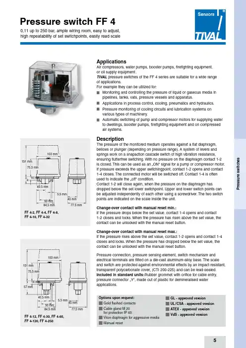
P r e s s u r e s w i t c h e s5ApplicationsAir compressors, water pumps, booster pumps, firefighting equipment, or oil supply equipment .TIVAL pressure switches of the FF 4 series are suitable for a wide range of applications.For example they can be utilized for:n Monitoring and controlling the pressure of liquid or gaseous media in pipelines, tanks, vats, pressure vessels and apparatus.n Applications in process control, cooling, pneumatics and hydraulics.n Pressure monitoring of cooling circuits and lubrication systems on various types of machinery.nAutomatic switching of pump and compressor motors for supplying water to dwellings, booster pumps, firefighting equipment and on compressed air systems.DescriptionThe pressure of the monitored medium operates against a flat diaphragm,b ellows or plunger (depending on pressure range). A system of levers and springs work on a snapaction cascade switch of high vibration resistance, ensuring flutterfree switching. With no pressure on the diaphragm contact 1-2 is closed. This can be used as an …ON“ signal for a pump or compressor motor.If pressure exceeds the upper switchingpoint, contact 1-2 opens and contact 1-4 closes. The connected motor will be switched off. Contact 1-4 is often used to indicate the …off“ condition.Contact 1-2 will close again, when the pressure on the diaphragm hasd ropped below the set lower switchpoint. Upper and lower switch points can be adjusted independently of each other using a screwdriver. The two switch points are indicated on the scale inside the unit.Change-over contact with manual reset min.:If the pressure drops below the set value, contact 1-4 opens and contact 1-2 closes and locks. When the pressure has risen above the set value, thec ontact can be unlocked with the manual reset button.Change-over contact with manual reset max.:If the pressure rises above the set value, contact 1-2 opens and contact 1-4 closes and locks. When the pressure has dropped below the set value, the contact can be unlocked with the manual reset button.Pressure connection, pressure sensing element, switch mechanism ande lectrical terminals are fitted on a die-cast aluminum-alloy base. The scale and switch are protected against environmental effects by an impact-resistant, transparent polycarbonate cover, (CTI 200-225) and can be lead-sealed.Included in standard units: Rubber grommet with orifice for cable e ntry, pressure connector …Y“, made out of plastic for demineralised watera pplications.Options upon request:n G old flashed contacts n C able gland M 20for protection IP 65n V iton diaphragm for aggressive media n M anual resetn G L - approved versionn U L / CSA - approved version n A TEX - approved version n V dS - approved versionFF 4-2, FF 4-4, FF 4-8, FF 4-16, FF 4-32103 mm5,5 mm40 mm 14 mm50 mm 84,5 mm77,5 mm151 mm75,5 mm 40,5 mmaFF 4-12, FF 4-30, FF 4-60,FF 4-120, FF 4-250103 mm5,5 mm40 mm 14 mm 50 mm 84,5 mm77,5 mm151 mm75,5 mm 40,5 mm57 mmControl pressure switch FF 4-... DAY Upper Lower Smallestswitch pt. switch pt. diff.*adjustable (bar) adjustable (bar) (bar) pressure (bar)0,11 ... 2 0,04 ... 1,89 0,07 0,110,22 ... 4 0,07 ... 3,75 0,15 0,250,5 ... 8 0,2 ... 7,5 0,3 0,5FF 4-10 DAY0,7 ... 10 0,3 ... 9,2 0,4 0,8FF 4-16 DAY 1 ... 16 0,4 ... 15 0,6 1Control pressure switch FF 4-... AAG / PAHUpper Lower Smallestswitch pt.switch pt.diff.*adjustable (bar)adjustable (bar)(bar)1 ... 120,5 ... 11,20,50,84 ... 30 1 ... 26,41,83,6High pressure switch with plastic plunger.Throttle is fitted as standard on these units. This must be removed for use with viscous media.Pressure connector: H (G 3/8“ Female thread, DIN 1725/2), stainless steel. VDE 0660, IEC 337-1, IEC 553-1Control pressure switch FF 4-... with manual reset Upper Lower Smallestswitch pt. switch pt. diff.adjustable (bar) adjustable (bar) (bar)0,11 ... 2 0,20,04 ... 1,89 0,10,22 ... 4 0,50,07 ... 3,75 0,20,5 ... 8 1,00,2 ... 7,5 0,41 ... 16 2,0Control pressure switch FF 444-... with UL / CSA-approval Upper Lower Smallestswitch pt. switch pt. diff.*adjustable (psi) adjustable (psi) (psi)3 ... 58 1 ... 54 2 415 ... 232 6 ... 217 9 14116 ... 870 58 ... 754 58 116P r e s s u r e s w i t c h e s10Media compatibility guideAccessoriesP r e s s u r e s w i t c h e s11Circuit diagramsChange-over contactwith manual reset min.Change-over contactwith manual reset max.Change-over contact DimensionsThrottle for FF 4-2 up to 32weight : ~ 3 g Order No.: 1011002Throttle screw for FF 4-12/30/60/120/250weight: ~ 3 g (stainless steel)Order No.: 10110035,5 mm6 mm4 mm G 3/8”G 1/2”Gauge fittingSteel, G 3/8” - G 1/2”, Type: H 124-114weight: ~ 18 g Order No.: 1071004P r e s s u r e s w i t c h e s12Pressure diagramsCharts show the smallest adjustable differential.Example per figure FF 4-4: If upper setting is at 3.25 bar, lower setting can be adjusted between 0.07and 3.0 bar (see arrows in the drawing).P r e s s u r e s w i t c h e s13Pressure diagrams。
压力开关说明7页
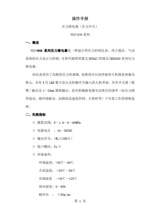
操作手册压力继电器(压力开关)YSJ-340系列一、概述YSJ-340系列压力继电器是一种超小型压力控制仪表,用于液压、气动系统的压力显示与控制,可替代德国贺德克HYDAC(贺德克)EDS300系列压力继电器。
该仪表采用了高精度压力传感器,电路部分以高性能单片机微处理器为核心,具有3位LED数字显示及轻触开关输入的人机界面、具有开关量(报警)输出及4~20mA模拟输出,是在机械继电器无法胜任的条件(如压力剧烈波动、强环境振动、高精度高速度控制、小体积等)下可靠工作的理想选择。
二、性能指标◇测量范围:0~1.6—0~60MPa◇电源电压:16~36VDC◇输出信号:(RL≤250Ω)◇接口螺纹:G1/4◇环境条件:环境温度:-20℃~60℃介质温度::-20℃~80℃存储温度:-40℃~125℃相对湿度:0~80%耐冲击:≤50g/ms耐振动:≤10g/(0~500HZ)◇输出信号精度:1.0◇过载压力:1.5%倍满量程压力◇最大功耗:≤3W触点容量:24VDC/1.2A(MAX)三、功能根据不同型号,装置可提供下列功能◇三位显示当前压力(正常工作)◇按压力、预设开关点输出开关量◇输出模拟量◇基本设定菜单◇提供四种不同输出模式:◇YSJ341带1路开关量输出(负载最大电流1.2A,无模拟量输出)◇YSJ342带2路开关量输出(负载最大电流1.2A,无模拟量输出)◇YSJ343带1路开关量输出(负载最大电流1.2A)和1路模拟量输出(4~20mA)◇YSJ344带2路开关量输出(负载最大电流1.2A)和1路模拟量输出(4~20mA)四、安装YSJ340可以通过压力管接头(DIN3852内螺纹G1/4),直接装在液压集成快上。
电气连接必须由国家认定合格的电工操作(参考中国电工国家标准规范)。
压力继电器的外壳必须同时良好的接地。
如安装在液压块里,块体通过液压系统接地时有保证的。
若用微型软管安装,客体必须单独接地。
Barksdale 2000型开关电子式双压力开关 说明书
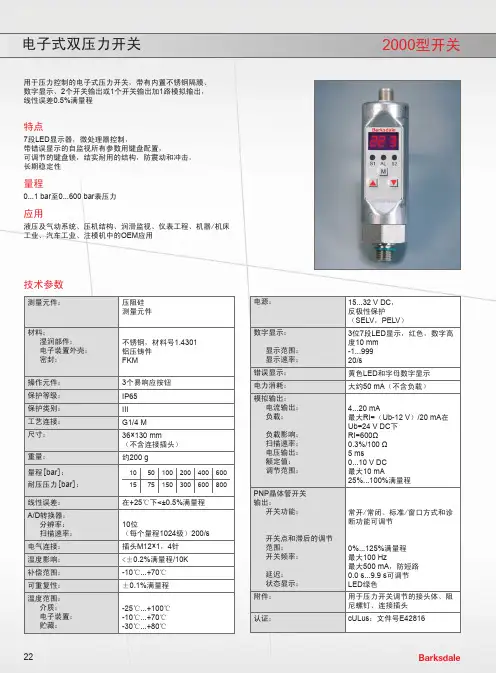
技术参数测量元件:压阻硅测量元件材料:湿润部件:电子装置外壳:密封:不锈钢,材料号1.4301铝压铸件FKM操作元件:3个易响应按钮保护等级:IP65 保护类别:III工艺连接:G1/4 M尺寸:36×130 mm(不含连接插头)重量:约200 g量程[bar]:耐压压力[bar]:1050100200400600 1575150300600800线性误差:在+25℃下<±0.5%满量程A/D转换器:分辨率:扫描速率:10位(每个量程1024级)200/s电气连接:插头M12×1,4针温度影响:<±0.2%满量程/10K 补偿范围:-10℃ (70)可重复性:±0.1%满量程温度范围:介质:电子装置:贮藏:-25℃ (100)-10℃ (70)-30℃ (80)电源:15...32 V DC,反极性保护(SELV,PELV)数字显示:显示范围:显示速率:3位7段LED显示,红色,数字高度10 mm-1 (999)20/s错误显示:黄色LED和字母数字显示电力消耗:大约50 mA(不含负载)模拟输出:电流输出:负载:负载影响:扫描速率:电压输出:额定值:调节范围:4...20 mA最大RI=(Ub-12 V)/20 mA在Ub=24 V DC下RI=600Ω0.3%/100 Ω5 ms0...10 V DC最大10 mA25%...100%满量程PNP晶体管开关输出:开关功能:开关点和滞后的调节范围:开关频率:延迟:状态显示:常开/常闭、标准/窗口方式和诊断功能可调节0%...125%满量程最大100 Hz最大500 mA,防短路0.0 s...9.9 s可调节LED绿色附件:用于压力开关调节的接头体、阻尼螺钉、连接插头认证:cULus:文件号E42816用于压力控制的电子式压力开关,带有内置不锈钢隔膜、数字显示、2个开关输出或1个开关输出加1路模拟输出,线性误差0.5%满量程特点7段LED显示器,微处理器控制,带错误显示的自监视所有参数用键盘配置,可调节的键盘锁,结实耐用的结构,防震动和冲击,长期稳定性量程0...1 bar至0...600 bar表压力应用液压及气动系统、压机结构、润滑监视、仪表工程、机器/机床工业、汽车工业、注模机中的OEM应用4• •• •3124针插头4...20 mAM12 x 112/ 0.47118/4.6412/ 0.47"A"六角螺母36ø 30/1.18工艺连接(螺纹“A ”,不带接头体):G1/4尺寸(mm /英寸)连接图订购代码描述0499-016用于压力开关最佳方位调整的接头体G1/4 IG-G1/4外螺纹901-0677带0.2 mm 节流孔限制快速压力变化和高脉动率的阻尼螺钉907-0357连接插头M12×1,4针,带螺钉端子,直角型907-0344连接插头M12×1,4针,带螺钉端子,直通型压力范围0...10 bar 0...50 bar 0...100 bar 0...200 bar 0...400 bar 0...600 bar 2路开关输出0428-0170428-0180428-0190428-0200428-0210428-0221路开关输出1路模拟输出4...20 mA0428-1270428-1280428-1290428-1300428-1310428-132插头订购代码附件按需提供更多的量程。
GW...A6 可调压力开关说明书
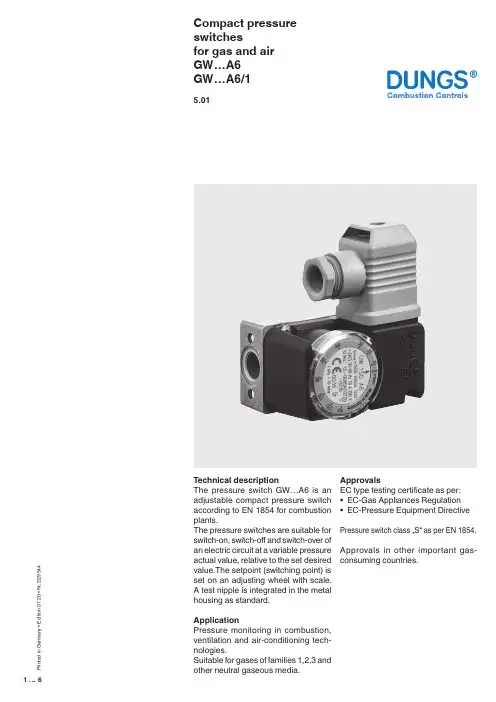
1 (6)Compact pressure switchesfor gas and air GW…A6GW…A6/15.01T echnical descriptionThe pressure switch GW…A6 is an adjustable compact pressure switch according to EN 1854 for combustion plants.The pressure switches are suitable for switch-on, switch-off and switch-over of an electric circuit at a variable pressure actual value, relative to the set desired value.The setpoint (switching point) is set on an adjusting wheel with scale. A test nipple is integrated in the metal housing as standard.ApplicationPressure monitoring in combustion, ventilation and air-conditioning tech -nologies.Suitable for gases of families 1,2,3 and other neutral gaseous media.ApprovalsEC type testing certificate as per: • EC-Gas Appliances Regulation • EC-Pressure Equipment Directive Pressure switch class …S“ as per EN 1854.Approvals in other important gas-consuming countries.P r i n t e d i n G e r m a n y • E d i t i o n 07.20 • N r . 229 544Functional descriptionSingle-acting pressure switch in over-pressure range.The pressure switches operate without any power supply.Switching responseGW…A6Short response time during pressure fluctuations.GW…A6/1Slow response time during short-term pressure fluctuations by additional damping nozzle.GW…A6 pressure switchThe control unit responds to pressure. If the setpoint is exceeded or undershot, the circuit is switched on, off or over.GW… / …A6 double pressure switchCombination of two flanged GW... A6 single pressure switches. The two setpoints are set separately and inde-pendently. A combination of different setpoint ranges is therefore possible. The two control units are fed from the same medium at the medium’s pres-sure.p↓ [mbar]p ↓ [mbar]2 (6)SpecificationsMax. operating pressure Pressure connectionMeasuring connection T emperature rangeMaterialsSwitching voltage Nominal current Switching currentElectrical connectionDegree of protection Setting toleranceDeviation GW 3 A6 - GW 150 A6 500 mbar (50 kPa)GW 500 A6 600 mbar (60 kPa)Standard (V0): centrally on housing bottom, G 1/4 inner threadas per ISO 228Special design (V3): additionally G 1/4 inner thread (side right)T est nipple integrated in metal housing ø9Ambient temperature -15 °C to +70 °CMedium temperatue -15 °C to +70 °CStorage temperature -30 °C to +80 °CHousing: Aluminium die castSwitch part: PolyamideDiaphragms: NBRSwitching contact: AgAC eff. min. 24 V max. 250 VDC min. 24 V max. 48 VGW 10…500 A6 GW 3 A6AC eff. max.10 A AC eff. max. 6 AAC eff. max.6 A at cos ϕ 1 AC eff. max. 4 A at cos ϕ 1AC eff. max.3 A at cos ϕ 0,6 AC eff. max. 2 A at cos ϕ 0,6 AC eff. min. 20 mA AC eff. min. 20 mA DC min. 20 mA DC min. 20 mA DC max. 1 A DC max. 1 AT erminal connection for line sockets as per DIN EN 175 301-803, 3-pin, protection-insulated without ground connectionIP 54 as per IEC 529 (EN 60529)± 15% switch point deviation referred to setpoint, adjusted for dropping pres-sure, vertical diaphragm positionPermissible deviation of the set value ≤ ± 15 % in the service life test according to EN 18543 (6)4 (6)Electrical connectionPressure connection5 (6)Compact pressure switchesfor gas and airGW…A6GW…A6/1Double pressure switchGW… / …A6We reserve the right to make any changes in the interest of technical progress.Head Offices and Factory Karl Dungs GmbH & Co. KG Karl-Dungs-Platz 1D-73660 Urbach, Germany T elefon +49 7181-804-0T elefax +49 7181-804-16Postal addressKarl Dungs GmbH & Co. KG Postfach 12 29D-73602 Schorndorf, Germany ******************** Internet 6 (6)。
压力开关双显使用说明书(2继电)_18014

P2系列双显数字压力开关使用说明书一、主要特点:1、开放式仪表参数设定2、采用防水结构,外形美观、安装方便;3、设定参数密码锁定,断电后永久保存。
4、同时显示动作点压力值(SV)与当前压力值(PV)二、技术参数·压力范围:0~0.5Kpa…50Mpa·控制精度:±1字·过载能力:1.5倍·动作时间:不超过1ms·使用环境:环境温度 0~50℃相对湿度≤85%RH避免强腐蚀气体·测量精度:0.5%FS ±1字·分 辨 率:1、0.1、0.01字·工作电压:DC24V·功 耗:≤5W·显示方式:-199~999测量值显示-199~999设定值显示·结 构:铝盒密封安装,防水·螺纹接口:M20 x 1.5·控制方式:两路开关量输出,可设置动作点、上/下限动作、回差/带差继电器控制模块(用户可选):0.3A at 220VAC;2A at 30VDC 三极管控制模块(用户可选):1.5A at 30VDC双向可控硅制模块(用户可选):5A at 250VAC·参数设定:面板轻触式按键数字设定,参数设定后永久保存。
参数设定值密码锁定 ·保护方式:继电器输出状态LED指示电源欠压自动复位工作异常自动复位(Watch Dog)三、操作方式1、正确的接线请参照仪表随机接线图(见附录)接妥输入、输出信号线及电源线,并请确认无误。
2、仪表的上电本仪表无电源开关,接入电源即进入工作状态。
四、控制参数设定 (一)、仪表面板项 目 功 能PV 显示测量值 显示实时测量值 显示AL1动作值与AL2动作值显 示 器 SV 显示动作点在参数设定状态下,显示参数符号或设定值按压然后抬起按下不放保持5秒 SET 参数设定键1) 在显示模拟量输出值时则进入一级参数设定,显示参数CLK 符号。
智能数显压力开关说明书
智能数显压力开关说明书智能数显压力开关是一种用于检测和控制液体或气体的压力的设备。
它采用先进的数字显示和电子控制技术,具有高精度、高可靠性和易操作的特点。
1. 外观和安装:智能数显压力开关的外壳通常为金属(如不锈钢),具有防水、防尘和抗震性能。
它可以通过螺纹连接或法兰连接安装在管道或容器上。
2. 数字显示:该压力开关具有清晰的数字显示屏,可以直观地显示当前的压力数值。
数字显示可以是液晶显示或LED显示,显示单位可根据需要设置。
3. 压力测量范围:智能数显压力开关可以测量不同的压力范围,通常以巴(bar)或千帕(kPa)为单位。
测量范围可以根据用户需求进行调整。
4. 控制功能:该开关可以通过设置高压和低压警报值来控制压力。
当压力达到或超过设定的警报值时,它可以自动触发报警或控制其他设备。
5. 防护等级:智能数显压力开关具有高防护等级,通常为IP65或更高,以保护其免受水、尘和其他外部物质的影响。
6. 输出信号:该开关可以提供模拟信号输出,如4-20mA或0-10V,以及继电器输出。
这些输出可以与其他设备(如数据记录器或PLC)连接,实现数据采集和远程控制。
7. 设定和调整:智能数显压力开关通常具有用户友好的菜单,可以通过按钮或旋钮进行设定和调整。
操作简单,无需额外的外部设备。
8. 适用领域:智能数显压力开关广泛应用于工业自动化、液压系统、空气压缩机、水处理等领域,以监测和控制压力的变化。
请注意,以上仅为智能数显压力开关的一般说明,具体产品的功能和操作方式可能会有所不同。
购买和使用前,请仔细阅读产品说明书和操作指南。
CKD 电子式压力开关PPX使用说明书
显示.操作部位的名称
输出1动作显示灯 比较输出1 ON时灯亮 输出2/模拟电压 输出动作显示灯 标准型: 比较输出2 ON时灯亮 高机能型: 模拟电压输出 设定时灯亮
模式切换键
主显示部位
̍
PPX
下部显示部位
设定值 上升键
设定值 下降键
压力气口
连接接插件
关于输出模式和输出动作
˔对于比较输出1和比较输出2,可以在简易模式、磁滞模式和窗口比较模式选择输出模式。 详细请参照“关于记忆设定模式”(12页)的〈比较输出1/2输出模式设定〉。
关于运转模式
终点数值的设定 ˔关于设定条件的设定方法,请参阅“关于记忆设定模式(”12页)中的〈比较输出1/2输出模式设定〉、〈模拟电压输出/外部输入切换〉。
PPX
在终点数值设定时,因仅仅在下部显示部位显示切换, 因此,下图的显示也仅仅在下部显示部位
ʢ注1ʣɿ超过设定压力范围的时候,下部显示部位“ ”(超过上限)或“
输出1:N.O.C. 输出2:N.O.
ʢ2.5msʣ 模式
ʢ5msʣ
主要显示部位的显示颜色切换
ɾɾɾɾɾ
ʢ5,000msʣ
ʢN.O.ʣ
ʢN.C.ʣ
ʢɹɹɹ ʣ ON时红色 OFF时绿色 模式
单位切换
ʢɹɹɹ ʣ ON时绿色 OFF时红色
ʢ通常红色ʣ
ʢ通常绿色ʣ
仅限于面向国外具有单位切换功能的场合。
ʢMPaʣ ʢ注3ʣ
模式
ʪ标准型的场合ʫ N.O./N.C.切换
ʢ注1ʣ ʢ注2ʣ
ʪ高机能型的场合ʫ N.O./N.C.切换 ʢ注2ʣ
ʢɹɹɹ ʣ 输出1:N.O. 输出2:N.O. 模式
hawe压力开关说明书
hawe压力开关说明书hawe压力开关是一种压力传感器,是一种可使压力保持恒定的开关。
它可广泛应用于石油、化工、医药、食品、冶金、机械等行业。
其作用是:对各个部件进行压力测试、对各部件进行压差调节、对压力报警。
与其它各类压力传感器相比, hawe压力开关具有操作简单、使用可靠、无噪音等特点。
产品主要有:油压表、电触点阀、压力保护等种类。
•一、使用说明hawe压力开关一般采用高精度电阻丝和半导体工艺制造,其工作原理如下:第一个压头的压力值达到设定值时,压差开关上锁紧按钮弹出,随后压力开关上被测介质压力将瞬间提升,此时在锁紧按钮弹出位置上有两个被测介质的压差,随后两个压头被分别拉动。
此时只要将压头拉动到设定位置即可使压力开关再次升压。
若压力开关再次上升,则压力传感器上锁按钮弹出位置将自动关闭。
当压力传感器下压时,压差开关上锁按钮弹出位置不变或继续下降至设置值时压力传感器上锁按钮弹出位置不再下降即可使压力开关再次升压。
如压力传感器继续下降至设定值时高压开关将被瞬间提升至高强度压力值时则压力传感器的上锁按钮弹出位置不变继续下降至压力开关关闭部位时压力传感器将被瞬间升高至高强度压力值。
•二、操作步骤a、操作:打开电源,启动电接点开关,指示灯亮,电接点开关指示灯灭。
c、压力调整:关闭电源并切断供电后,测量压力正常并将压力开关打开到最大处。
d、压差测量:压力开关打开到最大处并将压力开关关闭到最小处后,再测量压差大小及变化情况。
e、压力检测:将压力开关开到最大处并切断电源后,测量压力低于最大值时发出“嘟嘟”声并报警。
•三、注意事项不允许用水清洗电接点。
不允许在带电的情况下打开电气开关,尤其不要在潮湿的环境下使用。
在测试或测量压力时,必须按操作指示打开电接点开关(在没有使用电接点开关之前,不可开启任何电器)。
否则开关动作过程中会产生剧烈震动而损坏电接点。
请在使用之前进行以下步骤:(1)按下电源键启动电源开关;(2)检查并确认电接点处于通电状态;(3)按下手动按钮并按下启动键启动电触头开关;(4)检查是否出现漏电现象;(5)更换电阻片后对压力开关进行通电检测;(6)检查接触电阻是否达到要求;(7)检查电接点接触是否良好;(8)检查电接点是否接地正常;(9)压力开关进行通电测试前必须将电接线切断;(10)压力开关接通电源并用手将压力表按规定显示压力后方可进行操作。
Condor MDR 2 压力开关产品说明书
Page 3.08 Pressure switch MDR 2Single phaseSwitching capacity 2.2 kW Max. cut-out pressure 12 bar 2-pole (N.C.) Acc. to EN 60947Type overview MDR 2Order referenceON / OFF Rotary knobPressure range P OFF in barFlangeWeight in gPart No.MDR-2 DBA AAAA 015A030 XAA XXX EA 1.5 - 7 G 1/4" 300 212164 MDR-2 GBA AAAA 070A090 XAA XXX EA 4 - 12 G 1/4" 300 212171 MDR-2 GEA AAAA 070A090 XAA XXX EA 4 - 12 F4 1/4" 320 212188 MDR-2 GFA AAAA 070A090 XAA XXX EA 4 - 12 F4 3/8" 320 212195 MDR-2 GDA AAAA 070A090 XAA XXX EA 4 - 12 F4 1/2" 320 212201 MDR-2 DBA BAAA 015A030 XAA XXX - 1.5 - 7 F4 1/4" 300 217381 MDR-2 GBA BAAA 070A090 XAA XXX - 4 - 12 F4 1/4" 300 217404 MDR-2 GEA BAAA 070A090 XAA XXX - 4 - 12 F4 1/4" 320 219408 MDR-2 GFA BAAA 070A090 XAA XXX - 4 - 12 F4 3/8" 320 226888 MDR-2 GDA BAAA 070A090 XAA XXX-4 - 12F4 1/2"320226895Unloader valves and cable glands for retrofitting see Accessories!Technical Data MDR 2Technical Data MDR 2 acc. to 60947Technical Data MDR 2 acc. to 60947Rated insulation voltage U i500 V Permissible medium temperature Water+ 80 °C Motor switching capacity (AC 3) U e =240 V (1~)2.2 kW Degree of Protection acc. to EN 60529IP 44Electrical life (AC 3) Cycles> 1 x 10⁵Conductor cross-section 1 .. fine stranded cable 1 x / 2 x 2.5 / 2.5mm2Mechanical life Cycles> 5 x 10⁶Conductor cross-section 1 rigid cable 1 x / 2 x 2.5 / 2.5mm2Max. electrical cycles Cycles/h120Max. mechanical cycles Cycles/h600 Diaphragm media resistance MDR 2Rated operational current I e at 240 V AC20 A Air, WaterresistantBursting strength Pz> 35 bar Permissible medium temperature Air- 5...+ 80 °CA detailed overview of diaphragm media resistance for all pressure switches can be found in the table on page 2.11Dimensions / Circuit Diagrams MDR 2Pressure switch MDR-2Pressure switch MDR 2 Page 3.09Accessories MDR 2OrderreferenceDescriptionWeight in gPart No.Unloader valvesEV 2 With screw connection for 6 mm plastic or copper discharge tubes 25 200666 EV 2S With quick-connect for 6 mm plastic discharge tubes25 200680 EV 2W90° with screw connection for 6 mm plastic or discharge copper tubes 25 200697 EV 2Wi90° with screw connection for 1/4" mm plastic or discharge copper tubes 15 200703 EV 2WS 90° with quick-connect for 6 mm plastic discharge tubes 15 200710Delayed unloader valves AEV 2S With quick-connect for 6 mm plastic discharge tubes 25 200741 AEV 2W 90° with screw connection for 6 mm plastic or copper discharge tubes 15 200758 AEV 2Wi 90° with screw connection for 1/4" mm plastic or copper discharge tubes 15 200765 AEV 2WS 90° with quick-connect for 6 mm plastic discharge tubes 15 200772Cable glands WN Grommet 6 200888 PG 11 G Conduits for mounting of cable glands (Inner thread) 6 200895 PG 11 V Cable gland complete 12 200901 PG 11 Z With strain relief 12 200925 PG 11 ZK With strain relief and cable support 12 200918 PG 13.5 G Conduits for mounting of cable glands (Inner thread) 6 200963 PG 13.5 V Cable gland complete 12 200932 PG 13.5 Z With strain relief 12 200956 PG 13.5 ZK With strain relief and cable support 12 200949Cover H2 (Haube MDR 2)Cover without On/Off lever (Neutral version without marking) 40 217510 H2-EA (HaubeMDR 2+EA)Cover with On/Off lever for manual On/Off (neutral version, without marking) 40229445Unloader valves / Delayed unloader valvesEV 2EV 2SAEV 2SEV 2W / EV 2WiAEV 2W / AEV 2WiEV 2WSAEV 2WSPressure switch MDR 2Page 3.10 Cable glands MDR 2WNPG .. GPG .. VPG .. ZPG .. ZKDimensions, Accessories MDR 2EV 2EV 2SAEV 2SEV 2W / EV 2Wi AEV 2W / AEV 2WiEV 2WS AEV 2WSPressure DiagramsPressure switch MDR 2。
ydn5压力开关说明书
ydn5压力开关说明书
1.BETA压力开关属于精密仪器请正确放置或搬动。
2.BETA压力开关在达到设定点的(差压)压力或者温度时开关动作。
在按照说明书指示正确安装,该开关的设计与结构是完全免维护的。
3.切莫采用液态油或油脂润滑开关的任何部件。
4.除了更换外壳密封与安装支架外,不要移动或更换本开关的任何部件。
5.避免暴露在超高温、超低温、有侵蚀性环境中,-30~80℃为适宜温度。
6.调节螺丝有自锁性,所以在调节设定点后禁止封死调节螺丝。
7.安装前请详细检查铭牌上数据。
所有尺寸均以mm毫米标注。
8.如果您需要帮助请与供应商联系,开关只有在去污清洗后才能进行维护检修。
9.如果您需要额外的膜片O形圈和微动开关,请给出序列号向供应商购买。
10.开关的检修维护请由专业的仪表工程师实施。
11.除了更换膜片O形圈和微动开关以外,其它形式的检修维护有厂方执行。
12.非厂方检修维护的操作会影响产品本身的质量保证。
13.本章节的指导说明书的步骤也是安装步骤说明。
14.地基与工程环境的强烈振动可能会影响开关的正常功能。
- 1、下载文档前请自行甄别文档内容的完整性,平台不提供额外的编辑、内容补充、找答案等附加服务。
- 2、"仅部分预览"的文档,不可在线预览部分如存在完整性等问题,可反馈申请退款(可完整预览的文档不适用该条件!)。
- 3、如文档侵犯您的权益,请联系客服反馈,我们会尽快为您处理(人工客服工作时间:9:00-18:30)。
DG型气体压力开关
使用说明书
●请阅读和保持一个安全的地方
解释符号
●, 1, 2, 3 ... = 功能
➔ = 用法说明
所有工作必须在阅读操作说明后才能进行!
警告!不正确的安装、调整、修改、操作或维护可能导致伤害或物质损失。
使用前先阅读说明书。
这个单位必须安装依照本条例的实施。
标准声明
We, the manufacturer, hereby declare that the products DG.., marked with product ID No. CE 0085AP0467, comply with the essential requirements of the following Directives:
– 90/396/EEC in conjunction with EN 1854,
– 73/23/EEC in conjunction with the relevant standards.
The relevant products correspond to the type tested by the notified body 0085. Comprehensive quality assurance is guaranteed by a certified Quality System pursuant to DIN EN ISO 9001 according to annex II, para-graph 3 of Directive 90/396/EEC.Elster Kromschröder GmbH, Osnabrück
测试
➔电源电压、环境温度和外壳——看类型的标签。
➔最大介质温度:-15 + 80°C。
在系统暴露于更高的热应力、热设备上时压力开关必须安装在上游。
DG..B型
➔正压时1号位置为进气
DG..U型, DG..H型, DG..N型
➔正压时1号或者2号位置为进气,气体为空气、天然气或者烟气(其他位置密封),通风时气体从3号或者4号位置离开。
➔负压时3号或者4号位置为进气,气体为空气、天然气或者烟气(其他位置密封),通风时气体从1号或者2号位置离开。
➔对于压差时,用1号或2号和3号或4号,气体为空气、天然气或者烟气,其他位置密封。
➔在连接3号和4号位置时使用过滤垫,防止气体中的杂质弄脏电触点。
➔ DG..B, DG..U switch with rising pressure.
➔ DG..H switches and locks off with rising pressure – with manual reset.
➔ DG..N switches and locks off with falling pressure – with manual reset.
➔ Fit an upstream restrictor if the system is subject to greatly fl uctuating pressures (see acces-
sories).
➔ The service life will be shorter if subject to ozone concentrations exceeding 200 µg/m3.
Installation
➔Fitting position as required, pref-erably with diaphragm vertical, with unobstructed view of the adjustment dial. Ensure that no dirt or moisture can penetrate open ventilation ports.
➔ The housing may not contact masonry. Minimum clearance 20 mm.
➔ Avoid subjecting the DG to strong or violent vibrations.
➔ Condensation must not be allowed to get into the housing. At subzero temperatures malfunctions/failures due to icing can occur.
➔ When using silicone tubes, only use silicone tubes which have been suffi ciently cured.
➔ Continuous operation at high temperatures accelerates the ageing of elastomer materials.
➔ Protect from direct sunlight (even with IP 65).
DG..B..S
➔ Do not connect gas but only O2 or NH3 to the positive pressure port 1.Ensure that no grease is used during installation.
DG
1 Flush the pipework.
2 Use suitable sealing material.
3 If dirt can accumulate at port
3 or 4, use the fi lter, Order No. 74916199.
4 Fit the DG.
Tightness test
Adjusting the switching pressure ps
1Disconnect the system from the electrical power supply.
Wiring
DG
➔ 24–250 V AC:
I = 0.05–5 A, cos ϕ = 1,
I = 0.05–1 A, cos ϕ = 0.6;
DG..G
➔ 12–250 V AC:
I = 0.01–5 A, cos ϕ = 1,
I = 0.01–1 A, cos ϕ = 0.6;
12–48 V DC:
I = 0.1–1 A.
➔ If the DG..G has switched a voltage > 24 V and a current > 0.1 A once, the gold plating on the contacts will have been burnt through. It can then only be operated at this power rating or higher power rating.
➔ Contacts 3 and 2 close when subject to increasing pressure. Contacts 1 and 3 close when subject to falling pressure.
1Disconnect the system from the electrical power supply.
2 3 4
5。