机械式压力开关使用说明书
双簧机械压力开关调节说明书
双簧机械压力开关调节说明书双簧机械压力开关是一种常用的压力控制装置。
其作用是监测压力,当压力达到一定设定值时,开启或关闭电路。
这种开关特别适用于工业、农业和家庭设备中,需要对压力进行监测和控制的场合。
本文将详细介绍双簧机械压力开关的调节方法。
1. 调节压力范围首先,我们需要设计和调整双簧机械压力开关的压力范围。
压力范围的选择取决于所监测的对象的性质和压力大小。
假设我们要监测某个压缩空气罐内的压力,首先要知道该罐的压力最高可以达到多少,然后设置开关的开关量。
这里需要注意的是,双簧机械压力开关的压力范围是可调的。
我们可以通过旋转调节螺母调整最小压力值,并通过旋转调整螺柱调整最高压力值。
2. 调节压力差除了压力范围,我们还需要调节压力差。
压力差是指在压力测量过程中,开关的下限压力和上限压力之间的差值。
这种差异通常可调,以保证开关闭合的准确性。
要调节此参数,我们可以使用压力表来测量压力,并通过旋转调整螺柱或螺母来调整压力差值。
3. 连接电路调整好的双簧机械压力开关需要连接电路,以便于监控和控制压力。
我们可以根据设备的工作需求来设计电路。
电路的安装需要注意的是,在使用中请避免过度施加力量,以免机械部件损坏。
4. 维护和保养在使用中,双簧机械压力开关需要定期进行维护和保养。
首先,要确保机械部件清洁和润滑,以保证其正常运转。
其次,需要检查电路的连接情况和电路电源的稳定性,以确保其正常工作。
如果发现机械故障,请立即维修或更换。
综上所述,双簧机械压力开关是一种可靠的压力控制装置。
正确地调整其参数不仅能确保设备的稳定运行,还能延长其使用寿命。
使用过程中,我们需要定期进行检查和维护,以保证其正常工作。
Ashcroft G-Series和L-Series多功能压力开关说明书
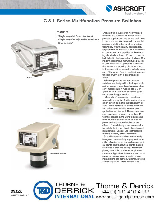
FEATURES• Single setpoint, fixed deadband• Single setpoint, adjustable deadband • Dual setpointAshcroft ®is a supplier of highly reliable switches and controls for industrial and process applications. We stress total value to the customer. We begin with rock-solid designs, matching the most appropriate technology with the safety and reliability requirements of the applications. Materials of construction are specified to the exact-ing standards of Ashcroft ®, and product is built to last in the toughest applications. Our modern, responsive manufacturing facility in Connecticut is supported by an exten-sive network of stocking distributors and factory sales offices located in v irtually every part of the world. Special application assis-tance is always only a telephone call away.Ashcroft ®pressure and temperatureswitches are designed for the tough appli-cations where conventional designs often don’t measure up. A rugged 316 SS or epoxy-coated aluminum enclosure gives uncompromising protection.Materials of construction have been selected for long life. A wide variety of pre-cision switch elements, including hermeti-cally sealed contacts for added reliability and safety are available to meet every application requirement. The actuators we use have been proven in more than 40years of service in the world’s plants and mills. Multiple features such as dual set-points and adjustable deadbands are offered. Special designs are available for fire safety, limit control and other stringent requirements. Ease of use is stressed to improve reliability of the installation.G- and L-Series switches are currently being used successfully in pulp and paper mills, refineries, chemical and petrochemi-cal plants, pharmaceutical plants, dairies,breweries, water and sewage treatment plants, steel mills, and other tough envi-ronments. Typical applications are on com-pressors, pumps, paint spraying equip-ment, boilers and burners, turbines, reverse osmosis systems, filters and presses.G-SeriesL-SeriesL-Series DifferentialNOTES:1. Switches may generally be set between 15% and 100% of nominal range on increasing or decreasing pressure.Consult factory for applications where setpoints must be lower.2. All deadbands are give The nominal range column.Deadbands shown are for switches with Buna N diaphragm. Approximate deadbands for optional diaphragms:Viton: Multiply Buna N value by 1.4Teflon: Multiply Buna N value by 1.2Stainless Steel: Multiply Buna N value by 1.7 Monel: Multiply Buna N value by 1.73. Deadbands for LPA, LDA, GPA, and GDA are adjustable between the values shown for all diaphragm materials.4. Deadbands for LPS, LPD, LDS, LDD, and GPS, GPD, GDS, GDD models are fixed within the range of values shown.5. Deadbands given are for zero static working pressure.6. Psid models cannot be used in vacuum applications.7. Proof pressure for stainless steel diaphragms is 4000 psi.G- and L-SERIES PRESSURE SWITCH AND DIFFERENTIAL PRESSURE SWITCH ORDERING INFORMATION1 – FUNCTIONGPS/LPS -Pressure control, single setpoint, fixeddeadband.GPA/LPA -Pressure control, single setpoint,adjustable deadband.GPD/LPD -Pressure control, two independentlyadjustable setpoints, fixed deadband.GDS/LDS -Differential pressure control, singlesetpoint, fixed deadband.GDA/LDA -Differential pressure control, singlesetpoint, adjustable deadband.GDD/LDD - Differential pressure control, two inde-pendently adjustable setpoints, fixed deadband.5 – PRESSURE CONNECTION (1)Order Code25 1⁄4NPT FemaleStandard on Pressure and D/P 06 1⁄4NPT Female and1⁄2NPT Male Combination Pressure Only 07 1⁄2NPT FemaleNOTES:1. These items are wetted by process fluid.2. Ambient operating temperature limits –20 to 150°F, all styles. Setpoint shift of ±1% of range per 50°F tempera-ture change is normal. Switches calibrated at 70°F refer-ence.3. Estimated dc rating, 2.5A, 28 Vdc (not UL listed).4. Estimated dc rating, 4A, 28 Vdc (not UL listed).5. Not UL listed at 480 Vac.6. Standard on G Series ˝H O ranges7. Supply static pressure for D/P switches.8. Stainless steel diaphragm only.9. Not available with Buna-N diaphragm.10. Available with GPS/LPS and GDS/LDS models.11. LDS, Buna N and Viton diaphragm only.12. LPS, stainless steel diaphragm only.13. All welded available on pressure models only.14. Order switch and 15-320SX-02T CG seal.15. Order switch and 20-320SX-02T CG seal.16. Not available for temperature ranges.17. Available on L-Series only.18. Not available with dual setpoints.7 – NOMINAL RANGESee page 3SWITCH ELEMENTS FOR FOR GPD/LPD,GPS/LPS, LDD/GDD & LDS/GDS CONTROLSCodeSingle DualSwitch elements UL/CSA listedK KK Narrow deadband 15A, 125/250 VacF FF Sealed environment 15A, 125/250 Vacproof15A, 125/250/480 Vac G GG General purpose 1/2A, 125 Vdc 1/4A, 250 Vdc Hermetically sealedP PP switch, narrow 5A, 125/250 Vac deadbandHermetically sealedJ JJ switch, general 11A,125/250 Vac purpose 5A, 30 Vdc W WW Ammonia service 15A, 125/250 Vac C CC Heavy duty ac 22A, 125/250 Vac S Heavy duty dc 10A, 125 Vac or dc⁄HP , 125 Vac or dc Y YY High temp. 300°F 15A, 125/250 Vac U UU Manual reset trip on 15A, 125/250 Vac increasingE EE Manual reset trip on 15A, 125/250 Vac decreasingHermetically sealedL LL switch, gold contacts 5A, 125/250 Vac M MM Low level, gold 1A, 125/250 Vac contacts2 – ENCLOSUREN4- NEMA 4, 4XL-Series: Epoxy Coated, Die Cast Aluminum, IP66G-Series: 316 SS IP656 – G-, L-SERIES PRESSURE SWITCH OPTIONSAvailable Differential Series Pressure Pressure Code Description G L psi ˝H O psid ˝H O XCH Chained Cover • • • • • • XFP Fungus Proof • • • • • • XFS Factory-Adjusted Setpoints • • • • • • XG5 Gas/OilUL Limit Control to 150 ˝H2O • •LDS only XG6 Gas/OilUL Limit Control to 600 psi • •LPS only XG8 Steam Limit Control to 300 psi • • XG9 Fire Safe Actuator • • High Operating Pressure for H2O Ranges:XHX 40 PSI Static (Pressure and D/P) • • • • 100 PSI Proof (Pressure) 160 PSI Proof (D/P)XJL ⁄˝ to ⁄˝ Reducing Bushing • • • • • • XK3 Terminal Blocks • • • • • • XNH Tagging Stainless Steel • • • • • • XPK Pilot Lights • • • • • XPM 3/4˝ Sealed Conduit Connectionwith 16˝ Lead Wires • • • • • • XTA 316SS Pressure Connectionfor ˝H2O Ranges • • • • XUD 316SS Pressure Connectionfor psid Ranges • • • X2C DPDT with Single SetpointAdjustment • • • • • • X6B Cleaned for Oxygen Service • • • • XFM FM Approval • • • • • X3A 1⁄˝ Sanitary Seal with Glycerin Fill • •2˝ Sanitary Seal with Glycerin Fill • •XHS High Static Operating Pressurefor PSI Range D/P • • • 4 – ACTUATOR SEAL (1)Process RangeCode Temp.(2) 2000- & Limits Vac 0-600 1000 3000 Material °F ˝H O psi psi psi B-Buna-N 0 to 150 • • • • V-Viton 20 to 300 • • • T-Teflon 0 to 150 • • • • S-St.St 0 to 300 • • P-Monel 0 to 300 •GP D N 4G G 25X K 330 PSIB1 2 3 4 5 6 7Additional options available, consult your Ashcroft representative.3 – SWITCH ELEMENTS FOR GPA/LPA,GDA/LDA CONTROLSDescription/Maximum Electrical Ratings Code UL/CSA listed 10A,125/250 Vac H General purpose 1/2A, 125 Vdc 1/4A, 250 Vdc Hermetically sealedJ switch, general 11A, 125/250 Vac purpose 5A, 30 VdcPressure Switch – psi RangesPressure Switch –Inches Of Water RangesDifferential Pressure Switch – Inches Of Water RangesDifferential Pressure Switch – psi Differential RangesHIGH PRESSURE PORTLOW PRESSURE PORTDimensions – G-SeriesPressure Switch – psi Ranges Pressure Switch –Inches Of Water RangesDifferential Pressure Switch –Inches Of Water Ranges Differential Pressure Switch –psi Differential Ranges4.126.091/4 NPT FEMALE4.12Dimensions – L-Series。
SS-2不同压力开关操作手册说明书
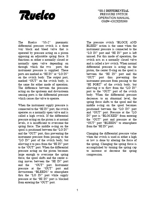
“SS-2 DIFFERENTIAL PRESSURE SWITCH OPERATION MANUAL OMP# 4202XDX000The pressure switch “BLOCK AND BLEED” action is the same when the instrument pressure is connected to the “LO IN” port and “HI IN” port is left unused. For this mode of operation, the switch acts as a normally closed valve and is called a low switch. When normal differential pressure is acting on the piston, the center O-ring on the spool is between the “HI IN” port and the “OUT” port thus preventing the instrument pressure from passing to the “HI PORT” of the switch body, but allowing it to flow from the “LO IN” port to the “OUT” port of the switch body. When the differential pressure decreases to an abnormal level, the spring force shifts to the spool and the middle o-ring on the spool becomes positioned between the “LO IN” port and “OUT” port. Pressure at the “LO IN” port is “BLOCKED” from entering the “OUT” port and pressure at the “OUT” port “BLEEDS” to atmosphere from the “HI IN” port. The Ruelco “SS-2” pneumaticdifferential pressure switch is a threeway block and bleed valve that isoperated by pressure acting on a pistonopposing an adjustable spring force. Itfunctions as either a normally closed ornormally open valve depending onthrough which the two ports theinstrument pressure is supplied. Theseports are marked as “HI IN” or “LO IN”on the switch body. The output port,marked “OUT” on the switch body, isthe same for either mode of operation.The difference between the pressuresacting on the upstream and downstreamsensing ports is the differential pressurewhich causes the valve to operate.When the instrument supply pressure isconnected to the “HI IN” port, the switchoperates as a normally open valve and iscalled a high switch. If the differentialpressure acting on the piston is at normallevels, it is insufficient to overcome thespring force. The middle o-ring on thespool is positioned between the “LO IN”and the “OUT” port, thus preventing theinstrument pressure from passing to the“LO IN” port of the switch body, butallowing it to pass from the “HI IN” portto the “OUT” port. When the differentialpressure acting on the piston becomeslarge enough to overcome the springforce, the spool shifts and the center o-ring moves between the “HI IN” portand the “OUT” port. Instrument pressure at the “OUT” port and downstream “BLEEDS” to atmosphere thru the “LO IN” port while supply pressure at the “HI IN” port is blocked from entering the “OUT” port.Changing the differential pressure value when the switch is used as either a high or low is done by altering the force of the spring. Changing the spring force is accomplished by turning the spring cap to increase or decrease the spring compression.2.0 INSTALLATION: 2. Small pliers.3. High quality silicone base lubricant.The “SS-2” differential can be panel mounted (with optional panel mount nut) or supported by piping from the sense port in either vertical or horizontal positions. If the switch is mounted horizontally, it is recommended that the small vent hole in the side of the switch body be oriented in a downward position. This will prevent any debris from accumulating in the spring cavity or above the sense piston. 4. An appropriate safety solvent. 3.1 PARTIAL DISASSEMBLY A) Spring Removal3.1.1)If the switch is installed in an operating instrument system, it is not necessary to remove any instrument supply or sense pressure. If the unit is a high switch, it will trip when changing the spring; if it is a low switch, then it will not. So precautions should be taken to avoid any unwanted reactions in the instrumentation system.Proper pipe thread sealant should be used on any pipe fittings threaded into the pressure switch ports. If stainless steel fittings are used, a sealant that will prevent galling is required. The supply gas flowing through the switch body should be filtered and free of large particles. If compressed air is used, it does not have to be lubricated. If natural gas is used as the instrument pressure, then it should contain as little condensate or crude oil as possible. This will extend the life of the seals. When the switch is mounted using the 1/4” NPT base connection and the instrument pressure ports are not in the desired position after the base connection is adequately tightened, DO NOT loosen the body from the base to re-position the ports. Instead, remove the switch and re-make the 1/4” NPT connection.3.1.2) To obtain access to the spring(Item 2), rotate the lock ring (Item 4) clockwise to loosen it from the spring cap (Item 1).3.1.3) Rotate the spring cap (Item 1)counterclockwise until it is disengaged from the switch body (Item 8).3.1.4) Remove the spring from itscavity in the switch body.3.0 DISASSEMBLY (See Spec Sheet)3.1.5) Follow the procedures in repairand assembly section (Steps 4.1.4 and 4.14) of this manual to re-install the spring.Tools and materials required for proper disassembly, repair and assembly are as follows: 1. 7/8” and 1” open end wrenchesor two crescent wrenches of adequate size.B)Piston Removal3.1.6)If the switch is panel mounted, itis not necessary to remove itfrom the panel. It will benecessary to disconnect anypiping or tubing from the basethat would prevent the base frombeing removed. When the switchis supported by the ¼” NPTconnection on its base (Item 12),disconnect any piping or tubingfrom the switch body that wouldprevent its removal from theswitch base. CAUTION: Be surethat all instrument or sensepressures are completely bled tozero before disconnecting anypiping or tubing.3.1.7)Use the appropriate wrenches tohold and loosen the base from theswitch body. Unthread the basecompletely from the switch body. 3.1.8)Unthread the lower housing(Item 18) from the baseassembly. Use appropriatewrench to loosen the hex nutItem 19) from the shaft-pistonassembly.3.1.9)Remove the installed cup seal(Item 16) from the piston (Item17).3.1.10)Procedure for re-installing thepiston cup seal and the shaft sealis in the repair and assemblyprocedure of this manual.3.2FULL DISASSEMBLYNOTE: Use the following instructions to completely disassemble the pilot for repair and cleaning. CAUTION: Be sure that all instrument or sense pressures are completely bled to zero before disconnecting any piping or tubing.3.2.1)Follow the procedures statedunder partial disassembly toremove the spring and piston.3.2.2)Remove the spool (Item 8) fromthe switch body. If it isnecessary, use the small pliersand grip the large end of thespool.3.2.3)The seals on the spool, (Item 8)may now be replaced as perinstructions given in the repairand assembly section of thismanual.4.0REPAIR AND ASSEMBLY(See product data sheet forreplacement part numbers).4.1)Remove the seals from the spooland piston.4.2)Clean all parts using anappropriate safety solvent.4.3)Inspect the spool for any majordamage such as burrs or nicks onits outside diameter. Also inspectit for straightness. Replace thespool (Item 10) if damaged.4.4)Examine the polished bores ofthe switch body (Item 8) andbase (Item 12) for gouges andrough surfaces. Be sure that allheavy dirt deposits have beenremoved. Replace any damagedpieces.4.13) Install the lock ring onto theswitch body and place the spring plate into the body cavity. NOTE : If the switch is panel mounted, install it into the panel and secure with a panel mounting ring prior to installing the lock ring (Item 4) and spring plate (ITEM 6). 4.5)Replacement seals from an authentic RUELCO REPAIR KIT is recommended to ensure proper switch performance. 4.6)Install new seals on the spool and lightly lubricate the seals and spool. CAUTION: Do not leave excessive lubricant on the spool. Doing so may prevent the switch from operating.4.14) Install the spring into the switchbody. CAUTION : Verify that the spring is the proper color for the range required as shown on the Range Selection Chart on the Specification Sheet $XXXX-12-95. 4.7)Verify the required switch range from the Range Selection Chart on the specification sheet 4XXX-12-95.4.8) Install the required cup seal (Item 16) on the large piston and the o-ring on the shaft (Item 20).4.15) Thread the spring cap onto theswitch body. Adjust the switch operation as per user requirements and methods.4.9)Lightly lubricate the piston seal and piston. DO NOT over lubricate or the switch performance may be adversely affected.4.10) Install the spool completely intothe switch body. Move it in and out of the body approximately ¼” to check that it moves freely.4.11) Install the shaft in to the pistonand tighten the hex nut. Install the shaft-piston assembly into the lower housing (Item 18) and grip the shaft on the shaft-piston assembly with the small pliers and move the piston back and forth in the base to verify that it moves freely. Thread the upper housing onto the lower housing.4.12) Thread the switch base into theswitch body and firmly tighten.5.0RECOMMENDED MAINTENANCEPROCEDURE MAINTENANCE5.1) Test Switch Trip Pressure Every 30 days5.2) Disassembly, inspect and lubricateYearlyorasrequired 5.3)Replaceallseals Every two years or as required 6.0TROUBLESHOOTINGPROBLEM1)Switch does notoperate when high orlow trip pressures areexceeded duringtesting or normaloperation.2)Gas or liquid leakingfrom small holebelow spring cap.3)Gas or liquid leakingfrom small holeabove switch base.4)Deadband and setpoint repeatabilityare larger than switchspecifications. PROBABLE CAUSEA)Switch adjustmenttampered with.B)Debris plugging sensorbody (Item 8) ports.C)Spring (Item 2)malfunction.D)Debris plugging thebase sense port or thepiston (Item 17).E)Spool seals (Item 7)and/or piston seal(Item 16) swollen.A)Damaged spool o-ring (Item 7).A)Damaged spool o-ring or guide sleeveseal (Item 9).A)Switch o-rings dry.B)Cause E for problem#1.RECOMMENDED ACTIONRe-adjust switch peroperating requirements.Disassemble switch as perprocedure in Section 3.0 andclean switch body. Cleaninstrument system filters.Remove the spring cap (Item1) and inspect spring (Item 2)for damage. Replace ifnecessary.Remove base and piston asper procedure in Section 3.0and clean. Begin cleaning ona regular basis.Disassemble as per procedurein Section 3.0 and 4.0. Trybetter filtration to keepcondensate out of supply gas.Disassemble and repair as perprocedures in Section 3.0 and4.0.Disassemble and repair as perprocedure in Section 3.0 and4.0Follow procedures in Section3.0 and4.0 to disassemblethe switch, lubricate all sealsand re-assemble.Same as problem #1.。
Switchgenie 电子压力开关机器人说明书
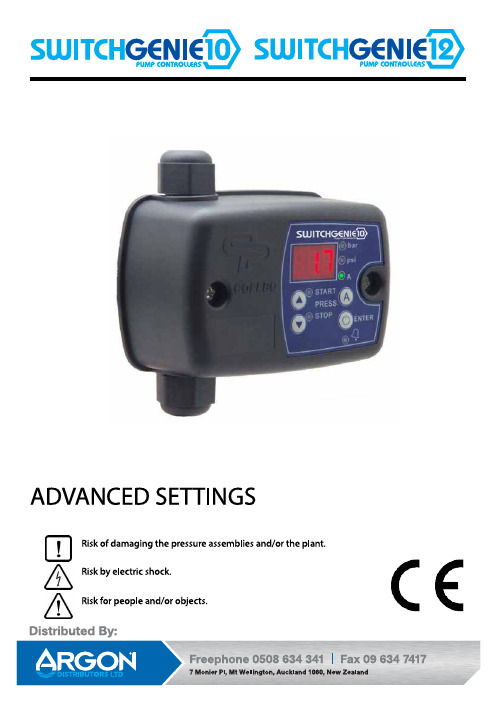
SWITCHGENIE 10 - SWITCHGENIE 12GENERALRead carefully the instructions before installing this unit. Verify the tech-nical characteristics of the motor in order to assure the compatibility with the device.DESCRIPTION (diagram A)SWITCHGENIE is an electronic pressure switch with integrated digital ma-nometer. It manages the start and stop of a single-phase pump up to 2.2kW (3 HP). Cut-in and cut-out pressures are easily adjustable through the users control panel.Wiring is analogous to the traditional electromechanical switch.It can operate as a differential pressure switch and as reverse pressure switch.Unit SWITCHGENIE 12 in addition to all the features of the basic SWITCH-GENIE includes instantaneous reading of current drawn. This patented system controls and manages the overcurrent, dry-run operation and fast-cycling.Unit SWITCHGENIE 12 in addition to all the features of individual assembly includes the option to be synchronized to another unit SWITCHGENIE 12 managing and protecting 2 pumps operating in cascade with alternated starting sequence.CLASSIFICATION AND TYPEAccording to IEC 60730-1 and EN 60730-1 this unit is a control sensor device, electronic, independent assembly, programming type A with action type 1B (microdisconnection). Operating value: I <20% I learned. Pollution degree 2 (clean environment). Rated impulse voltage: cat II / 2500V. Tem-peratures for ball test: enclousure (75) and PCB (125).OPERATING CHARACTERISTICS (diagram C)• Adjustable cut-in and cut-out pressures.• Integrated digital pressure gauge with bar and psi indication.• Inner pressure transmitter.• Dry-run protection:• Through minimum adjusted height for basic SWITCHGENIE.• Through the instantaneous current consumption in case of SWIT-CHGENIE 12.• Overcurrent protection (only SG12).• ART Function (Automatic Reset Test). When the device has stoppedthe pump by the intervention of the dry-running protection system, the ART tries, with scheduled basis, to re-start the pump in order to restore the water supply. See “ART. Automatic reset function“. Must be activated in the step 6 of the ADVANCED MENU (Ar1).• Fast cycling: when the hydropneumatic tank has lost too much air and, consequently, frequent start-stop cycles are produced this alarm isactivated and is delayed the start of the pump. Must be activated inthe step 2 of the BASIC MENU (rc1).• Manual start push-button (ENTER).• 3 operation modes: differential, reverse and synchronized (onlySG12).• Control panel with 3-digit display, LED indicator lights and push-buttons.• Volt-free contact for monitoring the alarms displayed in screen origi-nated by irregularities or problems of the system (only type SWITCH-GENIE 12A).• Available settings:• Stand-by mode.• Minimum period between fast cycles.• Start and stop delay.TECHNICAL CHARACTERISTICS• Rated motor power: 0,37-2,2 kW• Power supply: ~1 x 110-230 V• Pessure max. 0,8 MPa• Frequency: 50/60Hz• Max. current: 16 A• Protection degree: IP55• Max water Temperature: 50ºC• Max environment Temperature: 60ºC• Cut-in range (start pressure) 0,5÷7 bar• Cut-ot range (stop pressure) 1÷8 bar• Max. differential 7,5 bar• Minimum differential (adjustable) 0,5÷1,5 bar• Factory setting (start/stop) 3/4 bar• Hydraulic inlet G 1/4” Female• Net weight (without cables) 0,3 kg HYDRAULIC INSTALLATION (diagram A)SWITCHGENIE equipment must be threaded to a fi tting G1/4” male at the pump´s outlet.Before connecting the SWITCHGENIE verify that the hydraulic system is properly installed, especially if the hydropneumatic tank is pressurized. ELECTRIC CONNECTION (diagram B)The electric connection must be performed by qualifi ed personal in compliance with regulation of each country.Before doing manipulations inside the device, it must be disconnected from the electric supply.Wrong connection could spoil the electronic circuit.The manufacturer declines all responsability in damages caused by wrong connections.Check if power supply is between 115-230V.If you have purchased the unit without cables follow diagram B:• Use cables type H07RN-F 3G1 or 3G1,5 with section enough to thepower installed.• Do the pump connection U, V and .• Do the power supply connection L1, N and .• The earth conductor must be longer than the others. It will be the fi rst one to be mounted during the assembly and the last one to be dis-connected during the dismantling. T he earth conductors connec-tions are compulsory!CONTROL PANEL (diagram C)The meanings of the different control panel elements are summarized on the following tables, where:• O means lit LED light.• ( ( O ) ) means slow-fl ashing.• (((O))) means fast-flashing.STARTUP (diagram C)Before starting the device please read the previous sections, espe-cially “Hydraulic Installation” and “Electrical connection”.Follow next steps:1. Start the device by pressing .2. Only for type SG12 set the pump rated current intensity value.- Press during 3 seconds.- The current intensity value is displayed on screen, LED A lights up and display is fl ashing.- By mean of and is adjusted the rated current refl ected in the characteristics plate of the motor. See Note 1.- Press for validation.3. Set the cut-in (start) pressure:- Press during 3 seconds.- The start pressure value is displayed on screen, LED START lights up and display is fl ashing.- By mean of and is adjusted the start pressure from 0,5 to 7 bar.- Press for validation.4. Set the cut-out (stop) pressure:- Press during 3 seconds.- The stop pressure value is displayed on screen, LED STOP lights up and display is fl ashing.- By mean of and is adjusted the stop pressure from 1 to 8 bar.- Press for validation.5. The unit is ready to operate but more optional adjustments can be set through basic and advanced MENUS. See the next chapter.Remark 1: it is important to introduce exactly the rated current specifi ed on the nameplate of the pump.BASIC MENU + (diagram C)- Press simultaneously + during 5 seconds.- By mean of or the values can be changed.- Press for validation.ADVANCED MENU + +- Press simultaneously + + during 5 seconds.- By mean of or the values can be changed.- Press for validation.Remark 2:Basic SWITCHGENIE can only detect dry-running operation through the minimum pressure. This means that plumber must determine the water column of the installation, the start pressu-re of the pump and place the minimum pressure below the start pressure.It can also occur that pumping system is running out of its curve so that the pump is unable to provide the minimum pressure because the fl ow requirement is excessive. In this case SWITCHGENIE would activate a false dry-running alarm.If these concepts are not clear, it is preferable not confi gure this protection or install the SWITCHGENIE 12 with accurate and easy setting of dry-run detection.SYNCHRONISATION (ONLY FOR SWITCHGENIE 12)SWITCHGENIE 12 can be synchronized to another unit SWITCHGENIE 1managing and protecting 2 pumps operating in cascade with alternated starting sequence. Next steps must be followed:1. SET identical cut-in and cut-out pressures in both units.2. GO TO ADVANCED MENU: + +- In step 2in the other unit (this one will be the slave).- In step 3: select identical parameters of differential d.XX.3. Press repeatedly until exit the ADVANCED MENU.4. Press in order to disable the units. Is displayed “OFF”.5. Press again in both units in order to activate the synchronization.Remark 3: after 10 cycles the unit confi gured E01 will display pressu-re and the unit confi gured E02 will display current in Amps.ACCURATE DRY-RUNNING DETECTION (diagram C)In the SWITCHGENIE 12 model it is enough to set the rated current of the pump in order to activate the overcurrent and dry-running protection. However, the accuracy of dry-running detection can be improved by the activation of DR1 parameter in the ADVANCED MENU. The following steps must be followed:1. Drain the hydraulic installation and verify that the hydropneumatic tank is infl ated to the required pressure.2. Go to the ADVANCED MENU:- Press simultaneously + + during 5 seconds.- Press 7 consecutive times to accept and go to the next step until reaching dr0.- Using , set dr1.3. Press and close all the valves.4. The pump will start, will fi ll the installation and will stop at the cut-out pressure.5. Now, SWITCHGENIE 12 knows the current consumption curve of the pump.If you install a new pump this process should be repeated.If you enter the CURRENT INTENSITY MENU by pressing for 3 seconds all this process is invalidated because is predominant the rated current manually introduced.PRESSURE SENSOR CALIBRATIONIn case of wrong lecture of the pressure sensor it can be adjusted again. For the pressure sensor calibration is necessary to have a pressure gauge in the installation. Proceed following next steps:ZERO REGULATION1. Open the taps living the hydraulic net without pressure.2. Press simultaneously the buttons and until the display show0.0 fl ashing.3. Press to validate.FULL SCALE1. Start the pump until cut-out of the pressure switch.2. Press simultaneously the buttons and till the display fl asheswith a fi gure.3. Adjust the pressure with the arrows push-buttons to get the pressuredesired.4. Press to validate.Remark 4: pressure sensor decalibration should not be a normal event. If it is frequently repeated contact the technical service. WARNINGS AND ALARMSEC STAMENT OF COMPLIANCECOELBO CONTROL SYSTEM, S.L.States, on our own responsibility, that all materials here with related com-ply with the following European Directives:- 2014/35/EU.- 2014/30/EU.- 2014/65/EU.Name: - (SWITCHMATIC)- (SWITCHMATIC 2)Standards : EN-60730-2-6, EN-60730-1, EN-61000-6-1, EN-61000-6-3, IEC-60730-1, IEC-60730-2-6INDIVIDUALGROUP (ONLY SG12)DIAGRAM C DIMENSIONS。
GW...A6 可调压力开关说明书
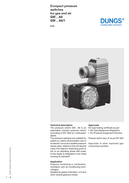
1 (6)Compact pressure switchesfor gas and air GW…A6GW…A6/15.01T echnical descriptionThe pressure switch GW…A6 is an adjustable compact pressure switch according to EN 1854 for combustion plants.The pressure switches are suitable for switch-on, switch-off and switch-over of an electric circuit at a variable pressure actual value, relative to the set desired value.The setpoint (switching point) is set on an adjusting wheel with scale. A test nipple is integrated in the metal housing as standard.ApplicationPressure monitoring in combustion, ventilation and air-conditioning tech -nologies.Suitable for gases of families 1,2,3 and other neutral gaseous media.ApprovalsEC type testing certificate as per: • EC-Gas Appliances Regulation • EC-Pressure Equipment Directive Pressure switch class …S“ as per EN 1854.Approvals in other important gas-consuming countries.P r i n t e d i n G e r m a n y • E d i t i o n 07.20 • N r . 229 544Functional descriptionSingle-acting pressure switch in over-pressure range.The pressure switches operate without any power supply.Switching responseGW…A6Short response time during pressure fluctuations.GW…A6/1Slow response time during short-term pressure fluctuations by additional damping nozzle.GW…A6 pressure switchThe control unit responds to pressure. If the setpoint is exceeded or undershot, the circuit is switched on, off or over.GW… / …A6 double pressure switchCombination of two flanged GW... A6 single pressure switches. The two setpoints are set separately and inde-pendently. A combination of different setpoint ranges is therefore possible. The two control units are fed from the same medium at the medium’s pres-sure.p↓ [mbar]p ↓ [mbar]2 (6)SpecificationsMax. operating pressure Pressure connectionMeasuring connection T emperature rangeMaterialsSwitching voltage Nominal current Switching currentElectrical connectionDegree of protection Setting toleranceDeviation GW 3 A6 - GW 150 A6 500 mbar (50 kPa)GW 500 A6 600 mbar (60 kPa)Standard (V0): centrally on housing bottom, G 1/4 inner threadas per ISO 228Special design (V3): additionally G 1/4 inner thread (side right)T est nipple integrated in metal housing ø9Ambient temperature -15 °C to +70 °CMedium temperatue -15 °C to +70 °CStorage temperature -30 °C to +80 °CHousing: Aluminium die castSwitch part: PolyamideDiaphragms: NBRSwitching contact: AgAC eff. min. 24 V max. 250 VDC min. 24 V max. 48 VGW 10…500 A6 GW 3 A6AC eff. max.10 A AC eff. max. 6 AAC eff. max.6 A at cos ϕ 1 AC eff. max. 4 A at cos ϕ 1AC eff. max.3 A at cos ϕ 0,6 AC eff. max. 2 A at cos ϕ 0,6 AC eff. min. 20 mA AC eff. min. 20 mA DC min. 20 mA DC min. 20 mA DC max. 1 A DC max. 1 AT erminal connection for line sockets as per DIN EN 175 301-803, 3-pin, protection-insulated without ground connectionIP 54 as per IEC 529 (EN 60529)± 15% switch point deviation referred to setpoint, adjusted for dropping pres-sure, vertical diaphragm positionPermissible deviation of the set value ≤ ± 15 % in the service life test according to EN 18543 (6)4 (6)Electrical connectionPressure connection5 (6)Compact pressure switchesfor gas and airGW…A6GW…A6/1Double pressure switchGW… / …A6We reserve the right to make any changes in the interest of technical progress.Head Offices and Factory Karl Dungs GmbH & Co. KG Karl-Dungs-Platz 1D-73660 Urbach, Germany T elefon +49 7181-804-0T elefax +49 7181-804-16Postal addressKarl Dungs GmbH & Co. KG Postfach 12 29D-73602 Schorndorf, Germany ******************** Internet 6 (6)。
pc30de压力开关说明书
pc30de压力开关说明书
pc30de压力开关(pc30d)是一种无源电磁触点式开关,具有超灵敏的压力感受器和阻尼转换器。
根据介质(protected particle)的不同,可选用以下类型:1.用于气体、液体等介质中;2.用于真空下工作的压力开关。
一、开关工作原理
在机械开关中,触点是指施加于气体、液体等介质的运动状态的触点。
压力开关所需的压力感受器,工作原理如下:当设备启动时,感应头接触高压信号而带动电磁缸高速旋转,同时触点上压紧弹簧使之产生回旋,带动压紧弹簧及压力传感器;当压力升高时,被控介质将释放出巨大的扭矩带动电磁缸高速旋转;当压力降低时,压力感受器弹簧产生一定的回旋,通过弹簧力的作用使被控介质释放气体或液体(或者蒸汽);压力改变时触点上压紧力自动改变感应头位置和大小。
二、基本组成
pc30de压力开关的基本组成由触发线圈、压力传感器、弹簧和触点组成。
其中触点为一种机械连接,工作于一定工作电压下,主要用于对介质直接施加压力。
对各种材料的压力传感器进行测量和转换。
弹簧与触脚组合在一起,以形成复位操作杆,用于控制开关动作和关闭操作。
弹簧和触脚通过橡胶连接在一起,用于橡胶密封。
触脚通过螺栓固定在弹簧座上。
三、使用注意事项
a.该开关可以工作在极低的工作温度下,且不会产生过大的振动。
b.该开关在工作时不会产生过载,且该设备具有自我保护功能,不会因为意外而损坏。
c.该开关具有压力自锁功能,可防止因误操作造成严重后果。
d.此开关可在零下40度到100度、0度到-50度、-60度到70度条件下工作。
铆压机 压力开关ZDOs使用说明书

0
R
S
Pma.x
当系统压力达到返回值时,输出=OFF
0
R
当系统=ON
Pma.x
R
S
当系统压力介于设定值和返回值之间时,输出=ON
0
R
Pma.x
S
当系统压力介于设定值和返回值之间时,输出=OFF
Pma.x
S
9
11. 出厂参数设置
数码压力开关产品使用说明书
MODE/ENTER:设定模式,确认 SET:设定参数值
在设定调节时不要使用尖锐状物调节,否则将会造成按键损坏。
2. 应用
ID-no 167050 165375
测量范围
允许最大压力
Bar 0 ...400 PSI 0 ...5800 MPa 0 ...40
Bar 0 ...10 PSI 0 ...145 KPa 0 ...1000
互联网信息
您可以通过登录托克斯®冲压技术有限公司Web地址:
了解更多的TOX®产品技术信息,如TOX®冲压连接
技术,TOX®气液增力缸技术,TOX®气液增力缸式冲压连接设备等信 息资料。
联系我们
深圳市王中王实业有限公司 SHENZHEN KINGWANG IND. Co.,Ltd 深圳市龙华镇同富裕华旺路经盛工业区三栋四层 4/F.,Blk3, JingSheng Ind . Zone, Huawang Rd. Longhua, shenzhen PRC 邮编:518109 Tel. 0086-0755-2814 0883 Fax. 0086-0755-2814 0882
显示单位:bar 精度:1% 设定范围:3 ~ 98%
显示单位:bar 精度:1% 设定范围:5 ~ 100%
《压力开关说明书》word版
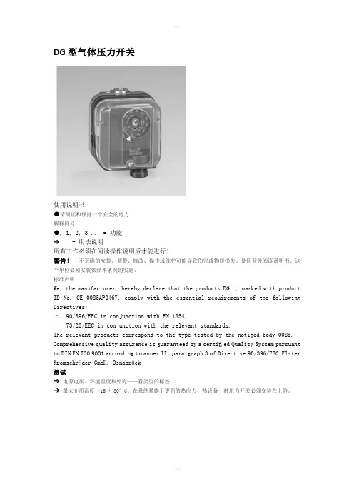
DG型气体压力开关使用说明书●请阅读和保持一个安全的地方解释符号●, 1, 2, 3 ... = 功能➔ = 用法说明所有工作必须在阅读操作说明后才能进行!警告!不正确的安装、调整、修改、操作或维护可能导致伤害或物质损失。
使用前先阅读说明书。
这个单位必须安装依照本条例的实施。
标准声明We, the manufacturer, hereby declare that the products DG.., marked with product ID No. CE 0085AP0467, comply with the essential requirements of the following Directives:– 90/396/EEC in conjunction with EN 1854,– 73/23/EEC in conjunction with the relevant standards.The relevant products correspond to the type tested by the notified body 0085. Comprehensive quality assurance is guaranteed by a certified Quality System pursuant to DIN EN ISO 9001 according to annex II, para-graph 3 of Directive 90/396/EEC.Elster Kromschröder GmbH, Osnabrück测试➔电源电压、环境温度和外壳——看类型的标签。
➔最大介质温度:-15 + 80°C。
在系统暴露于更高的热应力、热设备上时压力开关必须安装在上游。
DG..B型➔正压时1号位置为进气DG..U型, DG..H型, DG..N型➔正压时1号或者2号位置为进气,气体为空气、天然气或者烟气(其他位置密封),通风时气体从3号或者4号位置离开。
- 1、下载文档前请自行甄别文档内容的完整性,平台不提供额外的编辑、内容补充、找答案等附加服务。
- 2、"仅部分预览"的文档,不可在线预览部分如存在完整性等问题,可反馈申请退款(可完整预览的文档不适用该条件!)。
- 3、如文档侵犯您的权益,请联系客服反馈,我们会尽快为您处理(人工客服工作时间:9:00-18:30)。
机械式压力开关
型号:MD-S700
量程:0-25Bar
设定压力:10Bar
产品材质:不锈钢
量程:ZG1/4
出厂日期:
检验人员:
在使用本压力开关之前必须详细阅读此压力开关的有关资料和操作说明。
该系列压力开关为机械式压力开关,当流体压力作用在感压力元器件,使之产生形变,将向上移动,通过栏杆弹簧等机械结构,最终启动最上端的微动开关,使电信号输出。
该系列压力开关内部采用全不锈钢感压膜片,它的特点是使用方便,工作稳定,机械寿命长。
用户可通过随产品的附件工具设置控制点,或者是出厂时要求我厂预设好压力控制点。
该系列产品应用广泛,特别适合自动化设备配套,矿山机械等应用机械的压力控制及保护。
一.产品参数
产品量程0~0.2...1230Bar (根据客户选择不同,量程有差异)
设定压力0~0.2...600Bar (根据产品的量程不同,设定范围有差异)
测量介质水、油、气体等对不锈钢无腐蚀的流体
电气触点镀银
设定延时膜片式约为10% 活塞式约为15%
最高行程90次/秒
工作温度-20℃~80℃
机械寿命106 次
认证方式CE认证
重量60g
电气特性
可变式开关逻辑:常开和常闭
电源保护:根据DIN 40050标准
电源连接:根据DIN 43650标准
接线保护反极性和短路保护
安装接口G1/4 G1/2 或用户定制
材质不锈钢
二.连线方法
端子 定义
最大载荷
红色 报警公共端(COM 端) DC42V1A DC125V0.2A
AC42V3A AC125V3A
黑色 报警常开端(NO 端) 蓝色
报警常闭端(NC 端)
连线前必须确定使用电路中的电流电压是否超过压力开关的额定载荷! 连线时,必须切断电源以免造成人身伤害和产品的损坏!
三.尺寸图及电气连接图
*因防爆等级及客户要求不同,外形有差异。
四.注意事项
1.不得施加超过产品额定承载的压力!
2.不得通过超过产品额定承载的电流及电压!
3.不得测量对不锈钢或铜有腐蚀的介质!
4.不得带电连线或调节压力设定点!
5.强烈的碰撞可能会影响设定值,甚至会损坏产品。
6.防爆型产品在连线完成后,必须安装好产品的接头外壳及防护罩。
★ 因客户所订购的产品不同,本使用说明书可能有部分参数或内容与客户所收到的产品略微不
同,本说明书仅供参考,如发现问题,请与供应商联系。