起重机计算说明书
起重机数据及公式
起重机数据及公式引言概述:起重机是一种用于搬运和举升重物的重要工业设备。
在起重机的设计和操作中,准确的数据和公式是至关重要的。
本文将介绍起重机的数据和公式,匡助读者更好地了解起重机的原理和运行。
一、起重机的基本数据1.1 起重机的额定载荷:起重机的额定载荷是指起重机设计时所能承载的最大分量。
这个数据是根据起重机的结构和材料强度等因素计算得出的。
额定载荷是起重机设计和使用的重要依据,决定了起重机的使用范围和安全性能。
1.2 起重机的工作半径:工作半径是指起重机从起重点到起重物之间的水平距离。
工作半径的大小决定了起重机的搬运范围和作业空间。
在起重机的设计和操作中,需要根据工作半径来选择合适的起重机型号和配置。
1.3 起重机的提升速度:提升速度是指起重机在举升重物时的速度。
提升速度的快慢直接影响到起重机的工作效率和作业时间。
在起重机的设计和操作中,需要根据具体的工作需求来选择合适的提升速度,以确保作业的顺利进行。
二、起重机的动力计算公式2.1 起重机的起升力计算:起重机的起升力是指起重机在举升重物时所需施加的力量。
起升力的计算需要考虑起重物的分量、工作半径、提升速度等因素。
常用的起升力计算公式为:起升力 = 起重物的分量 / 提升速度。
2.2 起重机的回转力计算:起重机的回转力是指起重机在旋转时所需施加的力量。
回转力的计算需要考虑起重机的结构和工作半径等因素。
常用的回转力计算公式为:回转力 = 起重物的分量 ×工作半径。
2.3 起重机的行走力计算:起重机的行走力是指起重机在挪移时所需施加的力量。
行走力的计算需要考虑起重机的结构和行走速度等因素。
常用的行走力计算公式为:行走力 = 起重物的分量 ×行走速度。
三、起重机的稳定性计算3.1 起重机的倾覆力矩计算:起重机的倾覆力矩是指起重机在工作过程中产生的使其倾覆的力矩。
倾覆力矩的计算需要考虑起重机的结构、工作半径和工作状态等因素。
常用的倾覆力矩计算公式为:倾覆力矩 = 起重物的分量 ×工作半径。
起重机使用说明书
通用桥式起重机使用说明书ADDDD有限公司目录一、用途---------------------------------------------------3二、技术特性和主要参数----------------------------3三、结构概述--------------------------------------------3四、电气系统--------------------------------------------5五、安装、调试和运行-------------------------------6六、起重机的维护保养与润滑---------------------7七、起重机常见故障及处理------------------------16八、起重机的使用须知------------------------------23一、用途通用桥式起重机最为普遍地用于车间内和仓库中吊运工件和货物之用。
它是依靠沿厂房轨道方向的纵向移动、小车的横向移动和吊钩的升降运动来进行工作的。
本说明书所指的是一般用途通用桥式起重机和冶金用通用桥式起重机,前者主要适用于机械加工与装配车间、金属结构车间、机械维修车间、各类仓库、冶金和铸造车间的辅助吊运工作等,后者主要用于吊运赤热或熔态金属。
一般用途起重机不推荐用于高温(>+40°C)和低温(<-20°C)的场所、吊运赤热金属或熔态金属及具有强烈腐蚀性化学气体的工作场所。
二、技术特征和主要参数本系列桥式起重机的主要参数如下:(一)起重量: 5T 10T 16/20/5T 32/5T 50/10T六种规格(二)跨度:等八种规格(三)工作制度: A5(用于工作不太频繁,例如一般机械加工和装配车间)。
A6(用于工作较为频繁,例如冶金和铸造车间的辅助吊运)。
A7(用于繁忙使用及熔融、炽热金属的吊运)。
按确定的起重量、跨度和工作制度,可查阅随机附加的桥式起重机总图和小车图纸中的技术特性表和需要的外形尺寸参数。
门式起重机设计计算说明书
双梁门式起重机设计计算书(75.0吨18.0米)中铁宝桥有限公司2009年04月20日目录第一章设计初始参数-------------------------------------1 第一节基本参数--------------------------------------1 第二节选用设计参数----------------------------------1 第三节相关设计参数----------------------------------1 第四节设计许用值参数--------------------------------1 第二章起重机小车设计-----------------------------------3 第一节小车设计参数---------------------------------3 第二节设计计算(详见桥吊计算书)-------------------3 第三章门机钢结构部分设计计算---------------------------4 第一节结构型式、尺寸及计算截面---------------------4一、门机正面型式及尺寸---------------------------4二、门机支承架型式及尺寸-------------------------4三、各截面尺寸及几何特性-------------------------5第二节载荷及其组合---------------------------------7一、垂直作用载荷---------------------------------7二、水平作用载荷---------------------------------8三、载荷组合-----------------------------------12第三节龙门架强度设计计算---------------------------13一、主梁内力计算---------------------------------13二、主梁应力校核计算-----------------------------17三、疲劳强度设计计算-----------------------------19四、主梁腹板局部稳定校核-------------------------20五、主梁整体稳定性-----------------------------22六、上盖板局部弯曲应力---------------------------22第四节龙门架刚度设计计算---------------------------25一、主梁垂直静刚度计算---------------------------25二、主梁水平静刚度计算---------------------------26三、门架纵向静刚度计算---------------------------27四、主梁动刚度计算-------------------------------27第五节支承架强度设计计算---------------------------29一、垂直载荷作用下,马鞍横梁跨中截面内力计算-----29二、水平载荷作用下,马鞍横梁跨中截面内力计算-----35三、支承架各截面内力及应力-----------------------40第六节支承架刚度设计计算---------------------------45一、垂直载荷作用下,支承架的小车轨顶处位移-------45二、水平载荷作用下,支承架的小车轨顶处位移-------49第七节支腿整体稳定性计算---------------------------58 第八节连接螺栓强度计算-----------------------------60一、马鞍立柱下截面或上端梁截面的螺栓强度---------60二、支腿下截面螺栓强度计算-----------------------62 第四章大车运行机构设计计算-----------------------------65 第一节设计相关参数及运行机构形式--------------------65一. 设计相关参数---------------------------------65二. 运行机构型式---------------------------------65第二节运行支撑装置计算------------------------------66一. 轮压计算-------------------------------------66二. 车轮踏面疲劳强度校核-------------------------66三. 车轮踏面静强度校核---------------------------67第三节运行阻力计算----------------------------------67一. 摩擦阻力计算---------------------------------67二. 风阻力计算-----------------------------------68三. 总静阻力计算---------------------------------68第四节驱动机构计算----------------------------------69一. 初选电动机-----------------------------------69二. 选联轴器-------------------------------------69三. 选减速器-------------------------------------70四. 电机验算-------------------------------------70第五节安全装置计算----------------------------------71一. 选制动器-------------------------------------71二. 防风抗滑验算---------------------------------72三. 选缓冲器-------------------------------------72 第五章整机性能验算-------------------------------------74 第一节倾翻稳定性计算-------------------------------74一、稳定力矩-------------------------------------74二、倾翻力矩-------------------------------------74三、各工况倾翻稳定性计算-------------------------75第二节轮压计算-------------------------------------75一、最大静轮压-----------------------------------75一、最小静轮压-----------------------------------75第一章设计初始参数第一节基本参数:起重量 PQ=75.000 (t)跨度 S=18.000 (m)左有效悬臂长 ZS1=4.000 (m)左悬臂总长 ZS2=6.000 (m)右有效悬臂长 YS1=4.000 (m)右悬臂总长 YS2=6.000 (m)起升高度 H0=15.000 (m)结构工作级别 ABJ=5级主起升工作级别 ABZ=5级副起升工作级别 ABF=5级小车运行工作级别 ABX=5级大车运行工作级别 ABD=5级主起升速度 VZQ=5.000 (m/min)副起升速度 VFQ=9.280 (m/min)小车运行速度 VXY=38.500 (m/min)大车运行速度 VDY=32.100 (m/min)第二节选用设计参数起升动力系数 O2=1.20运行冲击系数 O4=1.10钢材比重 R=7.85 t/m^3钢材弹性模量 E=2.1*10^5MPa钢丝绳弹性模量 Eg=0.85*10^5MPa第三节相关设计参数大车车轮数(个) AH=8大车驱动车轮数(个)QN=4大车车轮直径 RM=0.800 (m)大车轮距 L2=9.000 (m)连接螺栓直径 MD=0.0240 (m)工作最大风压 q1=0/* 250 */ (N/m^2) 非工作风压 q2=0/* 600 */ (N/m^2)第四节设计许用值:钢结构材料Q235─A许用正应力〔σ〕I=156Mpa〔σ〕II=175Mpa许用剪应力〔τ〕=124Mpa龙门架许用刚度:主梁垂直许用静刚度:跨中〔Y〕x~l=S/800=22.50mm;悬臂〔Y〕l=ZS1/360=11.11mm;主梁水平许用静刚度:跨中〔Y〕y~l=S/2000=9.00mm;悬臂〔Y〕l=ZS1/700=5.71mm;龙门架纵向静刚度:主梁沿小车轨道方向〔Y〕XG=H/800=19.1mm;许用动刚度〔f〕=2.0Hz;连接螺栓材料 8.8级螺栓许用正应力〔σ〕ls=210.0Mpa;疲劳强度及板屈曲强度依GB3811-83计算许用值选取。
大汉塔机QTZ80(6010)说明书
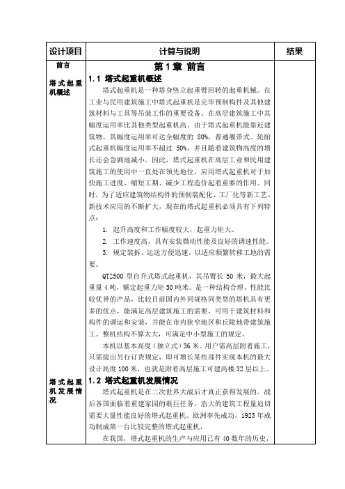
概 述QTZ80(6010)塔式起重机,是按国家标准设计的新型塔式起重机。
该机为水平臂架,小车变幅,上回转自升式多用途塔机,其主要特点如下:1、该机的各项性能参数及技术指标均达到国内领先水平,额定起重力矩80t·m,有效工作幅度 3~60 m,最大额定起重量6 t。
其中最大工作幅度达60米,独立式高度46米,附着式高度可达150米。
2、整机外型为国际流行式,美观大方,深受广大用户的喜爱。
3、本机工作速度快、高速性能好、工作平稳、效率高,起升机构基本上实现了重载低速,轻载高速;小车变幅机构具有两种速度满足工作需要;回转机构设有常开式停止器,使塔机就位准确,便于安全作业。
4、塔机安全保护装置齐全,配置有重量限制器、力矩限制器、高度限位器、回转限位器、小车断绳保护装置、小车断轴保护装置及起升、回转、变幅机构的制动器等安全装置,且均为机械式或机电一体化产品,灵敏可靠,能适应于恶劣的施工环境,确保塔机工作的安全可靠,同时还设有休息平台,护栏等劳动安全保护设施,以保障塔机装拆、检修及司机上下通行时的人身安全。
5、司机室独立外置,视野好,内部空间大,操作舒适、安全。
为操作者提供了良好的工作环境。
司机室通过先进的联动台操作各机构动作,操作容易,维修简单。
6、本产品的设计完全符合或优于有关国家标准。
该机在设计过程中,从钢结构的有限元计算、整机参数优化、整机稳定性验算到各机构选型等常规设计运算和全部绘图工作都是由计算机系统完成的,设计科学,制作精细。
基于以上特点,该型塔机既能满足中、小城市一般民用建筑需要,又能满足大、中城市高层或超高层民用建筑的需要,同时也可用于桥梁、水利工程、大跨度工业厂房以及采用滑模法施工的高大烟囱等大型建筑工程中,对港口、货场的装卸作业也能适用。
1.整机外形尺寸及技术性能1.1整机外形尺寸1.1.1独立式1.1.2附着式1.2起重特性 1.2.1起重特性表60米起重性能表幅 度(m ) 3~11 12 14 16 18 20 22 24 26 28 30 32 34 二倍 率 30002850 2620 24202240吊重kg四 倍 率 6000 5440476042203780341031002830 2600 23902210幅 度(m )36 38 40 42 44 46 48 50 52 54 56 58 60 二 倍 率 2080 1940 1810 1690159014901400132012501180 1110 10501000吊 重 kg四 倍 率2050 1910 1780 1670156014601380129012201150 1090 103097055米起重性能表50米起重性能表起重力矩曲线图1.3整机技术性能起重机技术参数表利用等U5 安装、拆卸、顶升或降节时最大安装高度处的风级≤4级 载荷状Q2 工作状态风级 ≤6级 工作级A5非工作状态风级 ≤11级参数名称单位 设计值 额定起重力矩 t.m 80 最大额定起重量 t 6 工作幅度m 3-60 最大幅度处额定起重量 t 1.0 独立式 m 46 二倍率m 150 高 度附着式 四倍率 m 75倍 率/ α=2α=4速 度 m/min 8.540 80 4.25 20 40起升速度相应最大起重量 t 331.5663电机型号 / YZTD225L 2-4/8/32功率kW 24/24/5.4 起升机构 转速 r/min 1383/699/141回转速度 r/min 0.6 电机型号 / YZR132M 2-6 功率 kW 2×3.7 回转机构 转速 r/min 908 变幅速度 m/min 48/24 电机型号 / YDEZ132S-4/8 功率 kW 2.2/3.3 变幅机构转速 r/min 1390/710 顶升速度m/min 0.55 液压系统额定工作压力 MPa 25 电机型号 / Y132M-4 功率kW 5.5 顶 升 机构 转速 r/min 1440 尾部回转半径 m 12.96 平衡重t 14.7 整机自重(不含平衡重) t 36.02 总功率kW40.21.4主要外购件及其技术指标型号/ YZTD225L 2-4/8/32功率 kW 24/24/5.4 电动机转速 r/min 1383/699/141 型号 / YWZ 3-315/45 制动器 制动力矩 N·m315-630 型号 / QTJ63 减速机速比/ i=15.07 钢丝绳/ φ132倍率 4倍率起升速度 m/min 8.540 80 4.25 2040 起 升 机 构 最大起重量t331.5663型号/ YZR132M 2-6 功率 KW 2×3.7 电动机 转速r/min 908 制动器/内置 回 转机 构 行星齿轮减速机减速比 / i=180型号/ YDEZ132S-4/8 功率 KW 2.2/3.3 电动机 转速r/min 1390/710 减速机 / 行星齿轮减速机变 幅 机 构 钢丝绳/φ7.7 型号/ Y132M-4 功率 kW 5.5 电动机转速r/min 1440 流量 L/min 10 液压泵站额定压力 MPa 25 液压油缸 型号/ HSGK-160/110E顶升机构行程mm16002.塔机主要构造及特点2.1总体布置2.1.1独立式独立高度46米,可采用二倍率或四倍率钢丝绳起升,塔身下部通过预埋支腿或井字架与基础相连,上部通过回转总成(下支座、回转支承、上支座)与回转塔身相连,司机室侧置于上支座,前方是吊臂,后方是平衡臂,起升机构设在平衡臂尾部,回转机构对称置于上转台侧边,变幅小车由变幅机构牵引,沿臂架来回作水平运动,起重臂、平衡臂均用刚性拉杆与塔帽连接。
250t门式起重机计算书
ME125+125/32t门式起重机计算说明书西南交通大学机械工程研究所2010年10月目录1 概述 (1)2 125+125/32t-37.435m门式起重机主要参数 (1)2.1主要设计参数 (1)2.2主要验算项目、方法和目的 (2)3 机构计算 (2)3.1主起升机构 (2)3.1.1钢丝绳 (2)3.1.2卷筒尺寸与转速 (2)3.1.3电动机 (3)3.1.4速比与分配 (3)3.1.5制动器选择 (3)3.2副起升机构 (4)3.2.1钢丝绳 (4)3.2.2卷筒尺寸与转速 (4)3.2.3电动机 (4)3.2.4速比与分配 (5)3.2.5制动器选择 (5)3.3小车行走机构 (5)3.3.1行走轮压计算 (5)3.3.2车轮组选择 (6)3.3.3电动机 (6)3.3.4速比与分配 (8)3.3.5制动器 (8)3.4大车行走机构 (8)3.4.1行走轮压计算 (8)3.4.2车轮组选择 (9)3.4.3电动机 (9)3.4.4速比与分配 (11)3.4.5制动器选择 (11)4 125+125/32t-37.435m门式起重机结构有限元计算 (11)4.1门架载荷计算 (11)4.2结构有限元计算 (13)4.2.1刚度验算 (13)4.2.2强度验算 (14)4.3门式起重机结构刚度和强度判定 (19)4.3.1静刚度计算讨论 (20)4.3.2强度计算讨论 (20)5 总体稳定性计算 (21)5.1总体稳定性计算 (21)6 结论 (22)7 参考书目 (22)1概述西南交通大学机械工程研究所依据委托方提供的参数,设计了125t+125/32t双小车门式起重机。
依据起重机设计规范(GB 3811–2008)、钢结构设计规范(GBJ 17-88),及《起重机设计手册》,对门机机构进行计算选型及校核,对门架结构的强度和刚度进行审核验算,并对整机的抗倾覆稳定性进行了校核计算。
2125+125/32t-37.435m门式起重机主要参数2.1主要设计参数125t+125/32t双小车门式起重机整机外型和主要参数如图2.1-1和表2.1-1所示:图2.1-1 125t+125/32t双小车门式起重机整机外型起升机构技术特性主起升机构副起升机构工作级别M5 M5额定起重量双小车125t+125t 32t起升速度 2.3m/min 9.2m/min卷筒直径Φ950mm Φ650mm滑轮倍率 6 4钢丝绳28NAT 6×19W+IWR 1870 ZS 521 318 20NAT 6×19W+FC 1670 ZS 220 147电动机YZR280M-8,55+55kW,725r/min YZR280M-8,55kW,725r/min减速器QJYD34-560-160 III C,i=160 ZQ-850-II-3CA,i=40.17制动器YWZ5-400/125,制动力矩:1600N.m YWZ5-400/125,制动力矩:1600N.m运行机构技术特性大车运行机构小车运行机构工作级别M5 M5行走速度20m/min 16m/min主/从动轮数16/16 4/4车轮直径Φ630mm Φ630mm轨道型号P50 QU80轨距37.435m 3.6m减速电机KDK10-143.47-YZRE3.7-4P-M4-J1-A(B)-T KDK12RF08-166-YZRE5.5-4P-M4-J1-A(B)-T制动器电机自带,制动力矩:50N.m 电机自带,制动力矩:50N.m1)门机机构选型计算依据125t+125/32t双小车门式起重机的设计图纸,根据工作参数,对门机的起升、运行机构进行选型及校核。
起重机规格说明书.pdf_1693890472.777498
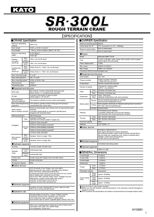
【SPECIFICATION】■CRANE Specifi cationMaximum rated liftingcapacity30ton×3mBoom length9.35m ― 30.5m (4 section)Fly jib length7.9m ― 13.0m (2 section, offset 5°,25°,45°)Maximum rated lifting height 31.2m (Boom) 44.8m (jib)Hoisting line speed (winch up)Mainwinch125m / min. (at 4th layer)Auxiliarywinch116m / min. (at 3rd layer)Hoisting hook speed (winch up)Mainwinch(Parts of line; 9) : 13.8m / min. (at 4th layer)Auxiliarywinch(Parts of line; 1) : 116m / min. (at 3rd layer)Boom derricking angle0°― 83°Boom derricking time40s / 0°― 83°Boom extending speed9.35m ― 30.5m / 93s Slewing speed 2.9min-1T ail slewing radius3,500mm●Equipment and structureBoom type Box-shaped, 4-section hydraulically terescopic type (Boom section 3 / 4 simultaneously operated)Jib type 2 sections (2nd section of draw-out type) (offset angles 5°,25°and 45°)Boom extension/retraction equipmentTwo hydrauric cylinders and wire ropes used togetherBoom derricking/lowering equipment One hydrauric cylinder of direct acting type with pressure-compensated fl ow control valveWinch systemMain & Auxiliary winches Driven by axial plunger type hoisting motor through planetary gear reduction.Controlled independently by respective operating lever. Equipped with automatic brake.Slewing equipment Ball bearing typeOutriggersTypeHydraulic H-beam type(with fl oat and vertical cylinder in single unit)Extensionwidth6,600mm (Fully extended)6,000mm (Intermediately extended)5,000mm (Intermediately extended)3,800mm (Intermediately extended)2,310mm (Fully retracded)Wire rope for hoistingMainwinchDiameter: 16mm×Length: 175mAuxiliarywinchDiameter: 16mm×Length: 95m●Hydraulic equipmentOil pump 4 pumps, plunger and gear typeHydraulic motor HoistingmotorAxial plunger typeSlewingmotorAxial plunger typeControl valve Double acting with integral check and relief valvesCylinder Double acting typeOil reservoir capacity500L●Safety devicesACS (Automatic Crane Stopper with voice alarm),Slewing automatic stop system, Outrigger status detector,Boom derricking / telescoping holding valve,Overhoist prevention device, Drum lock device (on aux. winch),Winch holding valve, Automatic winch brake,Winch drum roller, Hydraulic safety valves, Outrigger lock pins,Slewing lock, Joystick control safety stop system,Hydraulic oil temperature warning device,Hydraulic oil return fi lter warning device●Standard equipmentHydraulic oil cooler, Working light (on boom, table and cab),Winch drum turning indication device●Operator's cabAll steel welded construction, 1 person, Rubber mounted,Adjustable steering wheel, Adjustable seat, Seat belt,Front windscreen wiper & washer (2 speed wiper),Roof window wiper & washer, Cigarette lighter, Ashtray, Floor mat ●Optional equipmentWinch over unwinding device, Winch drum mirror (Hoist mirror),Cab heater, Cab cooler, Fan, AM/FM Radio,Fire extinguisher, Smoke torch ■CARRIER Specifi cationMaximum traveling speed49km/hGrade ability (tan θ)57% (computed at G.V.W. = 26990kg)Minimum turning radius(center of extreme outer tire)8.2m (2 wheel steer)4.9m (4 wheel steer)●EngineModel Mitsubishi 6M60-TLE3AType4 cycle, 6 cylinders, water cooled, direct injection turbo-chargeddiesel engine with intercoolingPiston displacement7.545LMax. power200kW at 2,600min-1Max. torque785N・m at 1,400min-1Fuel due to KATO's recommendation only●Equipment and structureDrive system4x2 / 4x4T orque converterEngine mounted 3 elements1 stage (with lock up clutch)Transmission Remote mounted full automaticNumber of speeds4 forward & 1 reverse speed(with HI - Low selector)AxlesFront Planetary, drive/steer typeRear Planetary, drive/steer typeSuspensionFront &RearT aper - leaf springHydraulic locking device with shock absorberBrake systemServiceAir-over hydraulic disk brake on 4 wheels(front and rear independent circuit)ParkingSpring applied, electrically air released parking brake mounted onfront axle, internal expanding typeAuxiliary Exhaust brakeSteeringFull hydraulic power steeringCompletely independent front and rear steering(with automatic rear wheel steering lock system)Tire sizeFront385 / 95 R25 170E ROADRear385 / 95 R25 170E ROADFuel tank capacity300 LBatteries(12V-120AH)×2●Safety devicesEmergency steering device,Rear wheel steering lock system (automatic),Mis-shifting prevention system, Brake fl uid leak warning device,Service brake lock, Suspension lock, Engine overspeed alarm,Radiator coolant level warning device,Air fi lter service warning device●Standard equipmentCentralized lubricating system●Optional equipmentYellow rev. light■GENERAL DimensionsOverall length11,360mmOverall width2,620mmOverall height3,475mmWheel base3,650mmTreadsFront 2,170mmRear 2,170mmPassenger capacity One personGross vehiclemassGrossweightapprox. 26,990kgFrontweightapprox. 13,000kgRearweightapprox. 13,990kg● Stow the hooks in place before traveling.●Before you use this machine, read the precautions in the instruction manual thoroughly tooperate it correctly.● KATO products and specifi cations are subject to improvements and changes without notice.■RATED LIFTING CAPACITYUnit : Metric ton 611-75101000611-7510200030.5m Boom+7.9m Jib30.5m Boom+13.0m Jib 30.5m Boom+13.0m Jib611-75103000■When the outriggers are not used611-75104000■Notes for the rated lifting capacity chart ■When the outriggers are used1. The rated lifting capacity charts are based on the jib stowed onthe boom side.2. The rated lifting capacity chart indicates the maximum loadwhich can be lifted by this crane provided it is level and standing on fi rm level ground. The values in the chart include the mass of the main hook and slings for boom operation, and auxiliary hook and slings for jib operation. [30 ton hook (mass: 250kg), 4 ton hook (mass: 80kg)]Within the chart the fi gures in the area bordered with a thick line are based on structural limitations while other figures are determined by stability limitations.3. The working radii are the actual values allowing for boom and jibdefl ection. Therefore you must always operate the crane on the basis of the working radius.4. The jib working radius is based on the jib mounted on the end ofthe 30.5m boom. When operating at other boom lengths, use the boom angle alone as the criterion.5. Do not operate the jib when the outriggers are completelyretracted.6. The lifting capacities for the over sides vary with the outriggerextension width. Therefore for each outrigger extension condition you should work according the rated lifting capacity chart.Use the rated lifting capacity chart of outriggers full extended forboth front and rear areas lifting capacities.Outrigger extension statusIntermediateextension (6.0m)Intermediateextension (5.0m)Intermediateextension (3.8m)Full retractionArea α◦35302037. The rated lifting capacity of the rooster sheave is the rated liftingcapacity of the boom minus the mass of all attached hook, slings etc. to the boom, with an upper limit of 4,000kg.[The hook for use with the rooster sheave is the 4 ton hook (mass: 80kg) with one part of line.]8. If the boom length, boom angle and/or working radius exceedsthe rated value, use the rated lifting capacity for the rated value or for the next one, whichever gives the smaller rated lifting capacity.9. If you are working with the boom while the jib is rigged, subtract2.2 ton plus the mass of all attached hook, slings etc. to theboom from the each rated lifting capacity of the boom, with an upper limit of 14 ton.Do not use the rooster sheave in this situation. And do not operate the boom while the jib is rigged, when the outriggers are retracted.10. In whatever working conditions the corresponding boom criticalangel is shown in the chart. The crane can tip over if the boom is lowered below the critical angle even if unloaded.Therefore, never lower the boom below these angles.11. The standard parts of line for each boom length are as indicatedin the chart. If you work with a non-standard number of parts of line, do not exceed 37.2kN (3.8tf) per wire rope respectively. 12. Crane operation is permissible up to a wind speed of 10m/s.Even in relatively light wind conditions, extra care should be taken when handling loads presenting large wind catching areas.13. Kato bears no liability whatsoever for damage, crane tipping orother accident caused by crane operations which differ from the directions contained in the instruction manual and the warning labels.■When the outriggers are not used1. The rated lifting capacity charts are based on the jib stowed onthe boom side.2. The rated lifting capacity chart indicates the maximum load thecrane can lift when its body is level on fi rm level ground with all tires inflated to the rated pressure and the suspension cylinder completely retracted. The values in the chart include the mass of the main hook and slings.Withinthechartthefi gures in the area bordered with a thick line are based on structural limitations while other figures are determined by stability limitations.[Rated tire pressure: 900kPa (9.0kgf/cm2)]3. The working radii are the actual values allowing for boomdefl ection. Therefore you must always operate the crane on the basis of the working radius.4. The rated lifting capacity differs between the front area capacityand the full range capacity. When slewing from the front to theside, take care that the crane could not be over loaded.Crane operationStationarycrane-on-rubberoperationPick and carryoperationArea α◦115. The rated lifting capacity of the rooster sheave is the rated liftingcapacity of the boom minus the mass of all attached hook, slings etc. to the boom, with an upper limit of 4,000kg.[The hook for use with the rooster shave is the 4 ton hook (mass: 80kg) with one part of line.]6. Do not work with the jib or with a boom length of more than23.45m.7. For stationary crane-on-rubber operation, the parking brake andservice brake lock device must be engaged.8. For pick and carry operation, the super-slow speed switch mustbe switched to “ON” and the shift lever set to speed 1.9. For pick and carry operation, lower the load to just above theground and keep your speed strictly below 2km/h to avoid swinging the load.Take particular care to avoid sharp turns, sudden starts and stops.10. Never operate the crane during pick and carry operation. Theslewing brake must be applied.11. If the boom length or working radius exceeds the rated value,use the rated lifting capacity for the rated value or for the next one, whichever gives the smaller rated lifting capacity.12. In whatever working conditions the corresponding boom criticalangel is shown in the chart. The crane can tip over if the boom is lowered below the critical angle even if unloaded.Therefore, never lower the boom below these angles.13. The standard parts of line for each boom length are as indicatedin the chart. If you work with a non-standard number of parts of line, do not exceed 37.2kN (3.8tf) per wire rope respectively. 14. Crane operation is permissible up to a wind speed of 10m/s.Even in relatively light wind conditions, extra care should be taken when handling loads presenting large wind catching areas.15. Kato bears no liability whatsoever for damage, crane tipping orother accident caused by crane operations which differ from the directions contained in the instruction manual and the warning labels.611-75105001■WORKING RANGE611-75107000■Minimum path width■Overall view* KATO products and specifi cations are subject to improvements and changes without notice.。
塔式起重机总体及顶升套架的设计计算说明书
总体设计方案的拟定金属结构安装基础当在保证所设计的机型达成国家有关标准的同时,力求结构合理,技术先进,积极性好,工艺简朴,工作可靠。
2.2总体设计方案的拟定QTZ500型塔式起重机是上回转、水平臂架、液压自升式的结构形式,由金属结构、工作机构和驱动控制系统三部分组成。
在进行总体设计时,要综合考虑塔机的强度、刚度、稳定性、各种工况下的外载荷以及塔机的经济性,从而选出合理的设计方案。
2.2.1 金属结构塔式起重机金属结构部分由塔身,塔头或塔帽,起重臂架,平衡臂架,回转支撑架等重要部件组成。
对于特殊的塔式起重机,由于构造上的差异,个别部件也会有所增减。
金属结构是塔式起重机的骨架,承受塔机的自重载荷及工作时的各种外载荷,是塔式起重机的重要组成部分,其重量通常约占整机重量的一半以上,因此金属结构设计合理与否对减轻起重机自重,提高起重性能,节约钢材以及提高起重机的可靠性等都有重要意义。
1.基础高层建筑施工用的附着式塔式起重机都采用小车变幅的水平臂架,幅度大部分在五十米以上,无须移动作业即可覆盖整个施工范围,因此多采用钢筋混凝土基础。
钢筋混凝土基础有多种形式可供选用。
对于有底架的固定自升式塔式起重机,可视工程地质条件,周边环境以及施工现场情况选用X形整体基础,四个条块分隔式基础或者四个独立块体式基础。
对于无底架的自升式塔式起重机则采用整体式方块基础。
X形整体基础的形状及平面尺寸大体与塔式起重机X形底架相似。
塔式起重机的X形底架通过预埋地脚螺栓固定在混凝土基础上,此种形式多用于轻型自升式塔式起重机,如图2-1所示。
2-1 X形整体基础长条形基础由两条或四条并列平行的钢筋混凝土底梁组成,其功能如同两条钢筋混凝土的钢轨轨道基础,分别支承底架的四个支座和由底架支座传来的上部荷载。
假如塔机安装在混凝土砌块人行道上,或是安装在原有混凝土地面上,均可采用这种钢筋混凝土基础,如图2-2所示。
分块式基础由四个独立的钢筋混凝土块体组成,分别承受由底架结构传来的整机自重及载荷。
起重机使用说明书三篇

起重机使用说明书三篇篇一:QTZ31.5自升式塔式起重机使用说明书一、概述QTZ31.5塔式起重机是建设部长沙机械研究院和我厂共同设计的一种新型起重机械,本机为水平臂架、小车变幅、上回转自升式塔机。
独立式起升高度为30m,附着式分60m起升高度和80m起升高度两种型式。
60m起升高度需要两层附着,80m起升高度需要四层附着,附着高度可根据建筑楼层作适当调整。
本机广泛用于办公大楼、工业厂房、民用住宅以及其它高层建筑的安装施工。
本机最大工作臂长42m,最大起重力矩315kNm,最大额定起重量3t,作业范围大、工作效率高,运行安全平稳、可靠。
QTZ31.5塔机还设有各种安全保护装置,包括:起重力矩限制器、最大起重量限制器、起升高度限位器、回转限位器和变幅限位器等。
从而保证了塔机安全可靠的运行。
QTZ31.5塔式起重机参数先进、性能可靠、造型美观、适用范围广,是广大中小建筑施工企业理想的起重设备。
二、起重机技术性能2.1起重特性表2.3技术性能参数表总电机功率:23.9KW供电电压:380V±10%供电频率:50Hz三、起重机构造简述QTZ31.5自升塔式起重机由金属结构、机械传动、液压顶升、电气控制以及安全保护装置等组成。
3.1总体布置塔机底架紧固于专用的混凝土基础上,其上部与塔机的标准节连接。
塔身通过下支座与回转支承连接。
紧固在回转支承以上的部分为转动部分,包括回转上支座、回转框架、塔顶、平衡臂、起重臂、牵引小车与吊钩、平衡重、起升机构、回转机构、以及操作室等。
这些部件均可绕塔身轴心线在各自的水平面内做360°的全回转。
起升机构设在平衡臂后部。
回转机构布置在回转上支座的平衡臂一侧。
牵引小车和吊钩由位于起重臂内的牵引机构牵引,沿起重臂纵轴线做水平往复运动。
起重臂用静定双吊点拉杆与塔顶连接,平衡臂则用两根拉索与塔顶相连。
操纵室置于回转框架右侧,其前方是起重臂,后面是平衡臂。
作业时,操作人员在操纵室内始终可以看到吊钩和重物的运动状况。
- 1、下载文档前请自行甄别文档内容的完整性,平台不提供额外的编辑、内容补充、找答案等附加服务。
- 2、"仅部分预览"的文档,不可在线预览部分如存在完整性等问题,可反馈申请退款(可完整预览的文档不适用该条件!)。
- 3、如文档侵犯您的权益,请联系客服反馈,我们会尽快为您处理(人工客服工作时间:9:00-18:30)。
2/1615)
8.06.0(1328762101501.296267cm N x =+⨯=τ
主梁在水平面内受水平惯性力和风力引起的剪应力一般较小,可略去不计
对于单主梁箱形门式起重机,其主梁截面除承受自由弯曲应力
外,还了在受约束弯曲应力、约束扭转正应力(以增大15%的自由弯曲应力计入)和剪应力。
此外,主梁截面还了在受纯扭转剪应力,现验算如下:
①弯心的位置发中图8-32所示,主梁截面弯心位置:
cm b Q Q Q e 87.387.906
.08.06.00212=⨯+=⨯+=
图8-32 主梁截面弯心计算简图
小车各部分重量如下:
G 1=4509kg ——小车上机械部分重量;
G 2=16322kg ——吊重及吊钩组重量; G 3=2490kg ——小车架及防雨罩重量。
②外扭矩 Mn=G 1l 1+G 2l 2+G 3l 3
=[(4509×122)+(16322×130)+(2490×155)]×9.8=299674.98N ·m ③ 主腹板上的剪应力
e=38.87cm
Mn=299674.98N ·m
τ1=1369.37N/c ㎡
τ2=1641N/c ㎡
2)支腿平面内的支腿内力计算τ1=
1
2Q
Mn
π
式中π=b0h0=90.7×150.8=13677.56c㎡
τ1=
8.0
56
.
13677
2
29967498
⨯
⨯
=1369.37N/c㎡≤[τ]
盖板厚度与主腹板厚度相同
④副腹板上剪应力
τ2=
6.0
56
.
13677
2
26933999
2
2
⨯
⨯
=
Ωδ
Mn
=1641N/c㎡≤[τ]
计算支腿内力时,可分别取门架平面和支腿平面的门架作为平面刚架进行计算,门架平面的刚架为一次超静定结构,支腿平面的刚架为静定结构。
①由主梁均布自重产生的内力(图8-33)由[1]表11-4可知,
有县臂时的侧推力为:
②
图8-33 支腿由自重引起的内力图
图8-34 支腿由移动载荷 图8-35 支腿由移动截荷 (在跨中)引起的内力图 (在悬臂端)引起的内力图 侧推力:H=[P1(K+x 1
)+P 2x ]×
h
k 21
323⨯+
=[136106.84(2.6+3.7)+136106.89×3.7] ×
N 36.416658
.921
3123=⨯⨯+⨯
弯矩M C =M D =Hh=41665.36×980
=-40832052N.cm
③ 作用在支腿上的风载荷产生的支腿内力(图8-36a 、b )作用
在支腿上的均布风载荷 引起的支腿内力。
④
H=41665.36N M C =M D
=-40832052N.cm
H A =2934.36N H B =509.31N
M C =-499123.8N.cm
2)支腿平面内 的支腿内力计算
图8-36 支腿由风载荷引起的内力图
侧推力
H A =)
312()18111(898013.43218118+⨯+⨯⨯
⨯=++⨯k k h q fII =2934.36N
H B =)
312()615(898013.432658+⨯+⨯⨯
⨯=++⨯k k h q fII =509.31N
弯矩M C =-H B h=509.31×980
=-499123.8N.cm
小车在跨中的支腿合成弯矩: ΣM C =-12131459.2-44287924-499123.8
-11045060.6=-437006.49N.m
Σ
M C =-437006.49N .m
Σ
M D =-205164.36N .m
Σ
M C =17218525N.m ΣM D
=40340621.2N.m
P C =377562.28N
V 1=204962.38N
V 2=172599.9N
M 1=327939.64N.m
M 2==932039.46N .m
2
05
.8777205.8458352213⨯
⨯⨯=+=h P h P M s s =400254N.m
③支腿承受从主梁传递据矩作用引起的支腿内力(图8-38C )已
知Mn=269339.99N.m
支反力 N l M V V n 38477700
99
.26933921==== 弯矩M 1=V 1l 1=38477×160=61563.42N.m
M 2=V 2l 2=38477×540=207775.8N.m M 3=M n =269339.99N.m
④支腿自重引起的支腿内力(图8-38d )已知支腿自重Gt=3853kg ,
a=160cm ,化为均布载荷 。
cm N q t /236160
8
.93853=⨯=
V 1=V 2=38477N M 1=61563.42N.m M 2=207775.8N.m M 3=269339.99N.m
1)水平刚度(图8-39a 、b )在水平载荷P S1、P S2作用下,支腿顶部的水平位移按式(8-30)计算:
△t1=∑∫Mps=1Mps/E ×ds
其中,单位水平载荷Ps=1引起的支腿内力为: V ´1=V ´2=h/l=8.05/7=1.15N M ´1= V ´111=1.15×160=184N ㎝ M 2´= V ´2L2=1.15×540=621N.㎝ M ´3=Psh=1×805=805N.㎝
在水平载荷P S1和P S2作用下引起的内力由前述所知P S1=45835N ;P S2=7772N
8
.91113442101.29148664
32
184160216
11⨯⨯⨯⨯⨯⨯⨯=∆
8
.9113442101.23087660
32
621540216
⨯⨯⨯⨯⨯⨯⨯+
△11=0.52cm
△22=0.52cm
2)支腿平面内轮压计算
轮压的合成
=
22
8
.9)]117.14558()6.366.4764[(3.1117141⨯⨯-⨯-⨯+
22
8
.9]22)4.18813853()21124[(⨯⨯++⨯
+22
8.9)]6.2566.4764()191316[(⨯⨯+⨯
V L
m ax =475818.80N
V L
A =V L E =237909.4N
V L
B =V L F =61014.16N
V t
A =V t
B =58198.22N
V t
E =V t
F =-37540.56N
V t
A =V t
B =58198.22N
毕业设计小结
起重机设计是我大学阶段最后一次也是最重要的一次作业.,在指导老师的指导下,在同学们的帮助下,自感收获很多.毕业设计是对学习成果的综合性总结和检验,是一次全面应用所学理论知识和专业知识的训练,提高了自己分析问题,解决问题和独立工作的能力.同时对整个起重机的设计方法有了初步了解,同时也提高了制定设计方案、调查研究、结构设计、等和计算机编程以及绘图和撰写技术文件的能
力以及查阅有关设计手册及图表资料的能力.在起重机的设计方面,基本掌握了机械原理的有关的内容、方法及步骤,这是一次机械知识综合学习和运用的机会.
在这次设计中,指导老师文庆明、王洪、刘忠伟进行了多方指导.对于老师的辛勤指导,在此深表谢意.
编者
参考文献
[1] 陈道南等编, 《起重运输机械》, 冶金工业出版社 1988年
[2] 中华人民共和国国家标准, 《起重机设计规范》(GB3811-83), 中国标准出版社 1984年
[3] 起重机设计手册编写组编, 《起重机设计手册》, 机械工业出版社 1979年
[4] 东北工学院<<机械零件设计手册>>编写组, 《机械零件设计手册》(第三版), 冶金工业出版社 1987年
[5] 《机械设计手册》, 冶金工业出版社 1996年
[6] 《现代工程制图》, 化学工业出版社 2004年
[7] 《通用机械》化学工业出版社 2004年
. .。