173R,AL,173R,BK,173R,GY, 规格书,Datasheet 资料
SLM-140;SLM-150;SLM-160;SLM-170;SLM-180;中文规格书,Datasheet资料
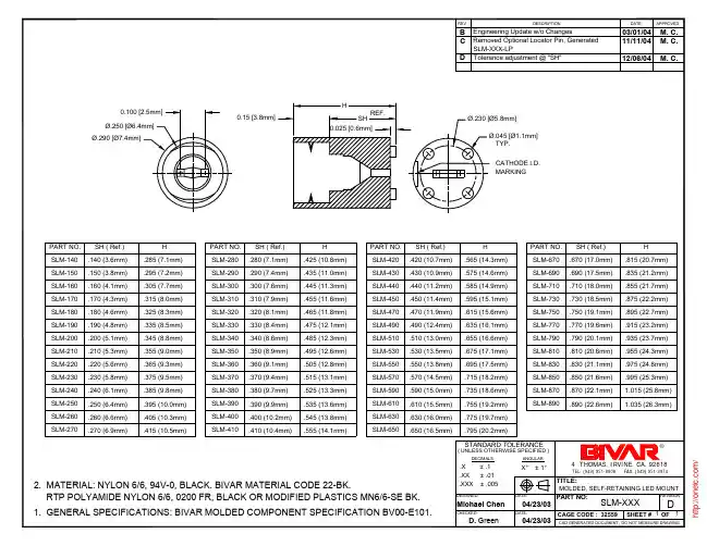
H .815 (20.7mm) .835 (21.2mm) .855 (21.7mm) .875 (22.2mm) .895 (22.7mm) .915 (23.2mm) .935 (23.7mm) .955 (24.3mm) .975 (24.8mm) .995 (25.3mm) 1.015 (25.8mm) 1.035 (26.3mm)
CHECKED:
04/23/03
DATE:
SLM-XXX
D
CAGE CODE : 32559
SHEET # 1 OF 1
D. Green
04/23/03
CAD GENERATED DOCUMENT, DO NOT MEASURE DRAWING., CA. 92618
M. C. M. C. M. C.
0.100 [2.5mm] Ø.250 [Ø6.4mm] Ø.290 [Ø7.4mm]
H 0.15 [3.8mm] SH REF. Ø.230 [Ø5.8mm] Ø.045 [Ø1.1mm] TYP. CATHODE I.D. MARKING 0.025 [0.6mm]
H .425 (10.8mm) .435 (11.0mm) .445 (11.3mm) .455 (11.6mm) .465 (11.8mm) .475 (12.1mm) .485 (12.3mm) .495 (12.6mm) .505 (12.8mm) .515 (13.1mm) .525 (13.3mm) .535 (13.6mm) .545 (13.8mm) .555 (14.1mm)
PART NO. SLM-420 SLM-430 SLM-440 SLM-450 SLM-470 SLM-490 SLM-510 SLM-530 SLM-550 SLM-570 SLM-590 SLM-610 SLM-630 SLM-650
MDL-ACIM;中文规格书,Datasheet资料
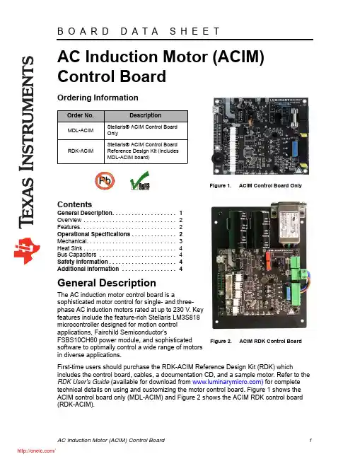
AC Induction Motor (ACIM) Control BoardOrdering InformationContentsGeneral Description. . . . . . . . . . . . . . . . . . . . 1Overview . . . . . . . . . . . . . . . . . . . . . . . . . . . . . 2Features. . . . . . . . . . . . . . . . . . . . . . . . . . . . . . 2Operational Specifications . . . . . . . . . . . . . . 2Mechanical. . . . . . . . . . . . . . . . . . . . . . . . . . . . 3Heat Sink. . . . . . . . . . . . . . . . . . . . . . . . . . . . . 4Bus Capacitors . . . . . . . . . . . . . . . . . . . . . . . . 4Safety Information. . . . . . . . . . . . . . . . . . . . . 4Additional Information . . . . . . . . . . . . . . . . . 4General DescriptionThe AC induction motor control board is asophisticated motor control for single- and three-phase AC induction motors rated at up to 230V. Key features include the feature-rich Stellaris LM3S818 microcontroller designed for motion control applications, Fairchild Semiconductor'sFSBS10CH60 power module, and sophisticated software to optimally control a wide range of motors in diverse applications.First-time users should purchase the RDK-ACIM Reference Design Kit (RDK) whichincludes the control board, cables, a documentation CD, and a sample motor. Refer to the RDK User's Guide (available for download from ) for complete technical details on using and customizing the motor control board. Figure 1 shows the ACIM control board only (MDL-ACIM) and Figure 2 shows the ACIM RDK control board (RDK-ACIM).Order No.DescriptionMDL-ACIMStellaris® ACIM Control Board OnlyRDK-ACIMStellaris® ACIM Control Board Reference Design Kit (includesMDL-ACIM board)Figure 1.ACIM Control Board OnlyFigure 2.ACIM RDK Control BoardOverviewThe MDL-ACIM motor control board controls three-phase and single-phase AC induction motors. The board has an integrated USB port (Virtual COM port) and logic-level serial port connections along with a quadrature encoder/tachometer input for speed and position monitoring. Extensive configuration options using Windows Graphical User Interface (GUI) are available and the board is easy to customize—full source code and design files are available.FeaturesThe MDL-ACIM motor control board provides the following features:End-user customizable line filter, bus capacitors, and JTAG interfaceSplit low-side current sensing for accurate current sensingDynamic braking circuitActive in-rush control circuitElectrically isolated JTAG port for software debugging or production programming (RDK only)Integrated AC line filter (RDK only)USB/Serial UART–FTDI FT232R USB to serial UART–Virtual COM port, 115.2k,8,n,1 operation–Stellaris MCC protocolOperational SpecificationsTable 1 shows the operating parameters for the MDL-ACIM motor control board.Table 1.MDL-ACIM Operating SpecificationsParameter Name Min Nom Max UnitAC Input Voltage (50/60Hz)230V operation195230265V AC 115V w/ voltage doubler95115135V ACDC Bus Voltage270320370V DC Frequency Range0400Hz Continuous Output Current 3.2A RMS Electrical Isolation2500V RMS Supply Current10A RMS Operating Temperature Range0–70°C Storage Temperature Range-25–85°C Digital Input Low Level Input Voltage-0.3 1.3V DCTable 1.MDL-ACIM Operating Specifications (Continued)Parameter Name Min Nom Max Unit Digital Input High Level Input Voltage 2.0 5.0V DC MechanicalFigure 3 shows the mechanical drawing for the MDL-ACIM.PCB size: 3.65" x 4.55" (93mm x115mm)Heatsink is required (MDL-ACIM only)Bus capacitors are required (MDL-ACIM only)Motor connector on PCB–RIA Connect part #31262104Power connector on PCB–RIA Connect part #31262102Figure 3.MDL-ACIM Mechanical DiagramHeat SinkThe ACIM motor module does not come with a heatsink like the RDK-ACIM, but does require a heatsink for operation. Underwriters Laboratories (UL) standards generally require that surfaces that could be touched by a user or service person must not exceed 70°C, so this must be considered when choosing the size material of the heatsink.Bus CapacitorsThe ACIM motor module requires that the customer supply bus capacitors for the board. The recommended capacitors to use are 1500uF, 200V electrolytic capacitors. Safety InformationWARNING – Risk of Electric ShockThe microcontroller in the RDK is not referenced to ground; it is at AC line potential. Do not make direct connection to the JTAG header or any other microcontroller-related circuit. Read the Quickstart Guide first for additional warnings.This RDK operates from AC line voltage. Improper use or application carries electric shock, fire, and other risks that may result in serious injury or death. Please read and follow these safety notices:This documentation and kit must only be used by people with training and experience in working with voltage potentials up to 230 V.The control board has both high-voltage potential and safety low-voltage sections.Do not connect high-voltage potential circuits to safety low-voltage circuits or to ground-referenced equipment such as computers or test equipment.After power is removed, high voltages remain until the bus capacitors discharge. Wait at least one minute after removing power before working with high-voltage circuitry.Use caution when using the on-board controls to adjust motor speed etc. High-voltage circuits are in close proximity.Never perform work on the control board, motor or, wiring while power is applied. Always wear eye protection and use care when operating the motor.In addition to safety risks, other factors that may damage the control hardware, the motor, and its load include improper configuration, wiring, or software. Minimize the risk of damage by following these guidelines.Additional InformationThe following documents are available for download at :RDK-ACIM User’s Manual, Publication Number RDK-ACIM-UMRDK-ACIM QuickstartCopyright © 2008–2009 Texas Instruments, Inc. All rights reserved. Stellaris and StellarisWare are registered trademarks of TexasInstruments. ARM and Thumb are registered trademarks, and Cortex is a trademark of ARM Limited. Other names and brands may be claimed as the property of others.RDK-ACIM-DS-01August 10, 2009Important NoticeTexas Instruments Incorporated and its subsidiaries (TI) reserve the right to make corrections, modifications, enhancements,improvements, and other changes to its products and services at any time and to discontinue any product or service without notice. Customers should obtain the latest relevant information before placing orders and should verify that such information is current and complete. All products are sold subject to TI’s terms and conditions of sale supplied at the time of order acknowledgment.TI warrants performance of its hardware products to the specifications applicable at the time of sale in accordance with TI’s standard warranty. Testing and other quality control techniques are used to the extent TI deems necessary to support this warranty. Except where mandated by government requirements, testing of all parameters of each product is not necessarily performed.TI assumes no liability for applications assistance or customer product design. Customers are responsible for their products and applications using TI components. To minimize the risks associated with customer products and applications, customers should provide adequate design and operating safeguards.TI does not warrant or represent that any license, either express or implied, is granted under any TI patent right, copyright, mask work right, or other TI intellectual property right relating to any combination, machine, or process in which TI products or services are used. Information published by TI regarding third-party products or services does not constitute a license from TI to use such products or services or a warranty or endorsement thereof. Use of such information may require a license from a third party under the patents or other intellectual property of the third party, or a license from TI under the patents or other intellectual property of TI.Reproduction of TI information in TI data books or data sheets is permissible only if reproduction is without alteration and isaccompanied by all associated warranties, conditions, limitations, and notices. Reproduction of this information with alteration is an unfair and deceptive business practice. TI is not responsible or liable for such altered documentation. Information of third parties may be subject to additional restrictions.Resale of TI products or services with statements different from or beyond the parameters stated by TI for that product or service voids all express and any implied warranties for the associated TI product or service and is an unfair and deceptive business practice. TI is not responsible or liable for any such statements.TI products are not authorized for use in safety-critical applications (such as life support) where a failure of the TI product would reasonably be expected to cause severe personal injury or death, unless officers of the parties have executed an agreementspecifically governing such use. Buyers represent that they have all necessary expertise in the safety and regulatory ramifications of their applications, and acknowledge and agree that they are solely responsible for all legal, regulatory and safety-related requirements concerning their products and any use of TI products in such safety-critical applications, notwithstanding anyapplications-related information or support that may be provided by TI. Further, Buyers must fully indemnify TI and its representatives against any damages arising out of the use of TI products in such safety-critical applications.TI products are neither designed nor intended for use in military/aerospace applications or environments unless the TI products are specifically designated by TI as military-grade or "enhanced plastic." Only products designated by TI as military-grade meet military specifications. Buyers acknowledge and agree that any such use of TI products which TI has not designated as military-grade is solely at the Buyer's risk, and that they are solely responsible for compliance with all legal and regulatory requirements in connection with such use.TI products are neither designed nor intended for use in automotive applications or environments unless the specific TI products are designated by TI as compliant with ISO/TS 16949 requirements. Buyers acknowledge and agree that, if they use any non-designated products in automotive applications, TI will not be responsible for any failure to meet such requirements.Following are URLs where you can obtain information on other Texas Instruments products and application solutions:Mailing Address: Texas Instruments, Post Office Box 655303, Dallas, Texas 75265Copyright © 2009, Texas Instruments IncorporatedProducts Applications AmplifiersAudio/audioData Converters Automotive /automotive DLP® Products Broadband /broadband DSPDigital Control /digitalcontrol Clocks and Timers /clocks Medical /medical Interface Military/militaryLogic Optical Networking /opticalnetwork Power Mgmt Security /security Microcontrollers Telephony/telephony RFID Video & Imaging /video RF/IF and ZigBee® Solutions/lprfWireless/wireless分销商库存信息: TIMDL-ACIM。
TEA1733PN1,112;中文规格书,Datasheet资料
3. Applications
All applications requiring efficient and cost-effective power supply solutions up to 75 W.
4. Ordering information
Table 1. Ordering information
C1 R1
C2 R2
R3
R4
Θ
Z1
TEA1733P
VINSENSE 5 PROTECT 6
4 ISENSE
R5
3 DRIVER
CTRL 7
OPTIMER 8
C3
2 GND 1 VCC
C4
R8
C5
S1 R10
R6
C6 R9
Fig 3. Typical configuration
R7
014aab131
7.2 Start-up and UnderVoltage LockOut (UVLO)
5 VINSENSE
014aab289
Fig 2. Pinning diagram SOT97-1 (DIP8)
6.2 Pin description
Table 2. Pin description
Symbol
Pin
VCC
1
GND
2
DRIVER
3
ISENSE
4
VINSENSE
5
PROTECT
6
CTRL
5. Block diagram
TEA1733P
GreenChip SMPS control IC
1 VCC
22 V
2 GND
131, 规格书,Datasheet 资料
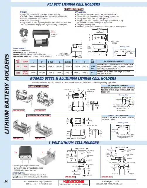
Tel (718)956-8900•Fax (718)956-9040(800)221-5510•kec@31-0720th Road –Astoria,NY 11105-2017RoHS COMPLIANT ~ISO 9001CERTIFIEDL I T H I U M B A T T E R Y H O L D E R SPLASTIC LITHIUM CELL HOLDERSRUGGED STEEL &ALUMINUM LITHIUM CELL HOLDERS6VOLT LITHIUM CELL HOLDERSFEATURES•Snap-In PC contact holds in position for wave soldering•Tin Nickel Plated contacts for excellent solderability and durability •Polarity clearly marked for orientation •Low Profile,space-saving•Snap-on retainer cover (optional)retains battery securely to withstand shock and vibration.Helps protect against shorting.Tamper-proof.APPLICATIONS•Computer memory,power transfer and back-up systems •Video and telecommunications power back-up requirements •Preprogrammed video and electronic games•Microprocessor,microcomputers,minicomputers,notebook,laptop and handheld computer memory hold applications •Emergency power systems•Residential,industrial and commercial security and fire alarm systemsSPECIFICATIONSBase:PBT,UL Rated 94V-0Retainer Cover:PBT,UL Rated 94V-0Contacts:.012(.30)Stainless Steel,Tin Nickel PlateOperating Temp Range:-60ºF to +290ºF (-50ºC to +145ºC)1.125 [28.58]POLARIZING TAB SPRING.648 [16.46].836 [21.25]REF..239 [6.06].600 [15.24].205 [5.21]TAB.125 [3.18] DIA.(2) PLS 1.656 [42.06]REF. 1.000 [25.40].750 [19.05].415 [10.54].187 [4.75]TAB108C,1029LC RETAINER COVER1029C RETAINER COVER•Polarizing Tab for proper orientation•Lightweight,ideal for rugged applications •DL223A or Equivalent Batteries SPECIFICATIONSFrame:Aluminum 2024-T3Terminals:Brass,Tin Plate Spring Contacts:.025(.64)Dia.Spring Steel,Nickel Plate•Sturdily constructed of quality materials •Contacts made from Brass,Nickel Plate •Ideal for punishing applications Mounting Detail.082[2.08]DIA HOLE (2)PLS.FOR P/N 131ONLY.118[3.0]DIA HOLE (4)PLS.1.557[39.5]1.125[28.6].437[11.1]Mounting Detail.082[2.1]DIA HOLE (2)PLS.P/N 21031.224[31.1].430[10.9].531[13.5].437[11.1].128[3.3]DIA.HOLE (2)PLS.144[3.7]DIA.HOLE.075 [1.9].750 [19.1].648 [16.5].600 [15.2]1.125[28.6].415 [10.5].750[19.1]1.000[25.4]1.656[42.1]REF..125[3.2] DIA.(2)PLS .238[6.1]SPRINGPOLARIZING TAB 223224CAT.NO.224CAT.NO.223CAT.NO.2103.606[15.4].356[9.0].625[15.9]1.156[29.4]REF..531[13.5].437[11.1].750[19.1].144[3.66]DIA.HOLE.128[3.25]DIA.HOLE (2)PLS.111[2.8]HOLE TYP.1.474[37.4]REF..625[15.9]1.125[28.6].625[15.9]REF..437[11.1].750[19.1].437[11.1]CAT.NO.1103CAT.NO.131CAT.NO.132CAT.CELL NO.COVER L W H (Ref)A B (MAX)F G SIZEBATTERY CROSS REFERENCE108108C1.160(29.5).640(16.3).633(16.1) 1.030(26.2) 1.360(34.5).610(15.5).279(7.1)“1/2AA”“CR2”10291029C1.500(38.1).720(18.3).712(18.1)1.375(34.9) 1.700(43.2).950(24.1).320(8.1)“2/3A”1029LC Energizer:544,CR2,Duracell:PX28L,CR2,Kodak:K28A &KS28,CR2,Panasonic:CR14250,CR2,Sanyo:CR14250SE,CR2,Saft:LCP3,Maxell:4LR44,CR2Duracell:DL2/3A,Kodak:K123L,Sanyo:CR173335SE,Saft:450SC &VR045020“1/2AA”•“CR2”•“2/3A”STEEL HOLDERS “1/2AA”ALUMINUM HOLDERS “2/3A”BATTERY CROSS REFERENCEEnergizer:544,Duracell:PX28L,Kodak:K28A &KS28,Panasonic:CR14250,Sanyo:CR14250SE,Saft:LCP3,Maxell:4LR44BATTERY CROSS REFERENCEDuracell:DL2/3A,Kodak:K123L,Sanyo:CR173335SE,Saft:450SC &VR0450.140[3.56].125[3.2]DIA.(2)PLS..062[1.57]DIA.X .062[1.57]L.LEGAFLB MAX.H REF..038[0.97]WMounting Detail.047[1.19]DIA..094[2.39]DIA.GL。
EL3H7(B)(TA)-VG,EL3H7(B)(TA)-VG,EL3H7(B)(TA)-VG,EL3H7(TA)-G,EL3H7(TB)-G, 规格书,Datasheet 资料

Option None -V (TA) (TB) (TA)-V (TB)-V (EA) (EB) (EA)-V (EB)-V Standard SMD option
Description
Packing quantity 100 units per tube 100 units per tube 5000 units per reel 5000 units per reel 5000 units per reel 5000 units per reel 1000 units per reel 1000 units per reel 1000 units per reel 1000 units per reel
Everlight Electronics Co., Ltd. Document No DPC-0000031
3 Rev. 3
Septemper 14, 2011
Revision
:3
芯天下--/
Release Date:2011-09-20 12:04:08.0 Expired Period: Forever
LifecyclePhase:
4 PIN ULTRA SMALL SSOP PHOTOTRANSISTOR PHOTOCOUPLER
Transfer Characteristics (Ta=25°C unless specified otherwise)
Parameter Collector-Emitter saturation voltage Isolation resistance Floating capacitance Rise time Fall time * Typical values at Ta = 25°C Symbol VCE(sat) RIO CIO tr tf Min. 5×10 10
74270055;中文规格书,Datasheet资料
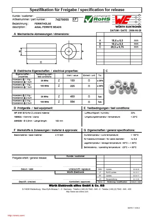
Bezeichnung :description :Eigenschaften / properties Wert / valueEinheit / unitTol.Impedanz @ 1 Wg./impedance @ 1 turn Impedanz @ 1 Wg./impedance @ 1 turnImpedanz @ 2 Wg./impedance @ 2 turn Impedanz @ 2 Wg./impedance @ 2 turn33%+ 20°C+ 150°C <= 9,8SMU Update 06-06-28LF RoHS update 04-10-11RTUpdate 02-04-17JH Neugestaltung00-12-06NameÄnderung / modificationDatum / dateAWG26 - ø 0,5mm - Länge/length:165 mm100 MHz25 MHz 25 MHz typ.± 25%Z typ.................................................................................................................................................................................................................................................Würth ElektronikZ225Z D Prüfgeräte / test equipment:HP 4191 B für/for Z und/and material 16092A - Klemme / clamp 453100 MHzΩ± 25%133ΩAXIAL FERRITE BEADSWürth Elektronik eiSos GmbH & Co. KGD-74638 Waldenburg · Max-Eyth-Strasse 1 - 3 · Germany · Telefon (+49) (0) 7942 - 945 - 0 · Telefax (+49) (0) 7942 - 945 - 400Geprüft / checked 554ZΩBasismaterial / base material:Curietemperatur / curie temperature: ΩDatum / date............................................................................Unterschrift / signature Kontrolliert / approvedTestbedingungen / test conditionsBetriebstemp. / operating temperature: -25°C ~ + 85°CF Werkstoffe & Zulassungen / material & approvals:4 W 620für Kabeldurchmesser / for cable diameter:Lagertemperatur / storage temperature: -55°C ~ + 85°C Kunde / customerFreigabe erteilt / general release:CB Elektrische Eigenschaften / electrical properties:E Testbedingungen / test conditions:Luftfeuchtigkeit / humidity:Umgebungstemperatur / temperature:G Eigenschaften / general specifications:Bezeichnung :description :A:B:SMU Update 06-06-28LF RoHS update 04-10-11RTUpdate 02-04-17JH Neugestaltung00-12-06NameÄnderung / modificationDatum / dateH Impedanzverlauf / impedance curve:2 x durch Bohrung Ferrit / 2 x times through ferrite 1 x durch Bohrung Ferrit / 1 x times trough ferriteFreigabe erteilt / general release:Kunde / customerD-74638 Waldenburg · Max-Eyth-Strasse 1 - 3 · Germany · Telefon (+49) (0) 7942 - 945 - 0 · Telefax (+49) (0) 7942 - 945 - 400Würth Elektronik eiSos GmbH & Co. KGDATUM / DATE : 2006-06-28AXIAL FERRITE BEADS..................................................................................Datum / dateUnterschrift / signature Würth Elektronik..........................................................................................................................................................................................................................................Geprüft / checked Kontrolliert / approvedThis electronic component has been designed and developed for usage in general electronic equipment. Before incorporating this component into any equipment where higher safety andreliability is especially required or if there is the possibility of direct damage or injury to human body, for example in the range of aerospace, aviation, nuclear control, submarine, transportation, (automotive control, train control, ship control), transportation signal, disaster prevention, medical, public information network etc, Würth Elektronik eiSos GmbH must be informed before the design-in stage. In addition, sufficient reliability evaluation checks for safety must be performed on every electronic component which is used in electrical circuits that require high safety and reliability functions or performance.分销商库存信息: WURTH-ELECTRONICS 74270055。
电源管理芯片AXP173 Datasheet
9.10 Host接口及中断(Host Interface and IRQ) ................................................................................... 27
18H 39H
9.11 寄存器(Registers) ........................................................................................................................பைடு நூலகம்.... 28
0H 21H
2.特性(Feature) ................................................................................................................................................ 4
目录 1.概述(Summary) ............................................................................................................................................ 3
19H 40H
10. 封装(Package) ........................................................................................................................................... 44
B82477R4105M100;B82477R4152M100;B82477R4153M100;B82477R4154M100;中文规格书,Datasheet资料
Applications
Terminals Base material Cu (L ≤10 µH), CuSn6P (L >15 µH) Layer composition Ni, Sn (lead-free) Electro-plated Marking Marking on component: Manufacturer, L value (µH, coded), manufacturing date (YWWD) Minimum data on reel: Manufacturer, ordering code, L value, quantity, date of packing Delivery mode and packing unit 24-mm blister tape, wound on 330-mm reel Packing unit: 350 pcs./reel
1.2 1.0 0.8 L / µH 0.6 2.0 0.4 0.2 0.0 0 5000 10000 15000 20000 Idc [mA] 25000 30000 35000 40000 1.0 0.0 0 2000 4000 6000 8000 10000 12000 14000 16000 18000 20000 Idc [mA] L/µH 4.0 3.0 820nH 5.0
Identification/Classification 1 (header 1 + top left bar): Identification/Classification 2 (header 2 + bottom left header bar): Ordering code: (top right header bar) Series/Type: (bottom right header bar) Preliminary data (optional): (if necessary) Department: Date: June 2012 B82477R4 SMT power inductors Size 12.5 x 12.5 x 8.5 (mm)
223,AL,223,BK,223,GY, 规格书,Datasheet 资料
A
.10 typ. .26 2 plc's
1.85 Insert Area .31 4 plc's
.09 typ. for #4 screw
TOP
1.28
BOTTOM
2.81
PART NO. 2-3 22 1095 6005 DESCRIPTION (Included) TOP BOTTOM Battery Cover #4X3/8” self tapping (2) ACCSESSORIES (Optional) PART NO. 319 419 DESCRIPTION Prototype grid board (Bottom) Prototype clad board (Bottom)
芯天下--/
223 (user print)
2.60 2.50 .70 .02
Battery compartment cover
A
1.63 .50 .44 4.10
.25 2 plc's
1.63
1.25 Insert Area
1.63 .04 X .02 deep
4°
223 (3D exploded)
-Click on image to show toolbar. Use to Play/Pause Animation. -Left click and drag on image to move 3D model.
W 2.61 L 4.10
H 2.50
PART NO. 2-3 22 1025 6005
Notes: (Enclosure weight 0.21 lb / 98 gm) 1) Enclosure meets or exceeds IP40 and NEMA 1 2) Top Circuit Board drawings can be download at:
172R,AL,172R,BK,172R,GY, 规格书,Datasheet 资料
PART NO. 7-2R 17 6018 6102
DESCRIPTION (Included) TOP BOTTOM 4-40 SCREW (6) THREADED INSERTS (6)
ACCSESSORIES (Optional) PART NO. PS17 370 470 DESCRIPTION Perimeter Seal Prototype Grid Circuit Board Prototype Clad Circuit Board
Water proofing gasket PS17 optional. see note #2
3D model options: a) Zoom in & out with center wheel. b) Pause at any moment to view and or print views. c) Change the views to ortho and section views if needed from the Views pull down menu. d) Explore options included in the tool bar like: Views, Transparency of model, Lighting type, etc.
芯天下--/
172R (user print)
4.88 2.00 .70 .02 4.00 Insert Area
A
.25 6 plc's .04 X .02 deep 2.00 Insert Area
6.88 6.43 Insert Area
.63
.50
2.25
A
172R (3D exploded)
- 1、下载文档前请自行甄别文档内容的完整性,平台不提供额外的编辑、内容补充、找答案等附加服务。
- 2、"仅部分预览"的文档,不可在线预览部分如存在完整性等问题,可反馈申请退款(可完整预览的文档不适用该条件!)。
- 3、如文档侵犯您的权益,请联系客服反馈,我们会尽快为您处理(人工客服工作时间:9:00-18:30)。
Notes: Enclosure weight .50 lbs / 229 gm 1) Enclosure meets or exceeds IP40 and NEMA 1 2) When used with PS17 the enclosure meets or exceeds IP 67 and NEMA 4X, 12 and 13 MIL-STD-810G 506.5 .32 SECTION A-A 3) Circuit Board drawings can be download at: 6 plc's Top: SCALE 1 : 2 /Accessories/CircuitBoard/drawings/X73_CB.pdf Bottom: ALL DIMENSIONS ARE ± .010" 7/29/10 (2 of 2) /Accessories/CircuitBoard/drawings/370-470-cbg.pdf 2009 Wright Ave. La Verne, CA 91750 4) All components are RoHS Compliant. Ph. (626) 331-0517 Fx. (626) 331-8584
PART NO. 7-3R 17 6019 6102 DESCRIPTION (Included) TOP BOTTOM 4-40 SCREW (6) THREADED INSERTS (6) ACCSESSORIES (Optional) PART NO. PS17 370 470 DESCRIPTION Perimeter Seal Prototype Grid Circuit Board Prototype Clad Circuit Board
-Click on image to show toolbar. Use to Play/Pause Animation. -Left click and drag on image to move 3D model.
173R (3D exploded)
4.88 W
6.88 L
2.50 H
Threaded inserts only have to be assembled the first time.
Notes: Enclosure weight .50 lbs / 229 gm 1) Enclosure meets or exceeds IP40 and NEMA 1 2) When used with PS17 the enclosure meets or exceeds IP 67 and NEMA 4X, 12 and 13 MIL-STD-810G 506.5 3) Circuit Board drawings can be download at: Top: /Accessories/CircuitBoard/drawings/X73_CB.pdf Bottom: ALL DIMENSIONS ARE ± .010" 7/29/10 (1 of 2) /Accessories/CircuitBoard/drawings/370-470-cbc.pdf 2009 Wright Ave. La Verne, CA 91750 4) All components are RoHS Compliant. Ph. (626) 331-0517 Fx. (626) 331-8584
.10 typ.
.31 16 plc's
.09 typ. for #4 screw
.26 16 plc's
.31 typ. 16 plc's
.26 typ. 6 plc's
BOTTOM
PART NO. 7-3R 17 6019 6102 DESCRIPTION (Included) TOP BOTTOM 4-40 SCREW (6) THREADED INSERTS (6) ACCSESSORIES (Optional) PART NO. PS17 370 470 DESCRIPTION Perimeter Seal Prototype Grid Circuit Board Prototype Clad Circuit Board
Water proofing gasket PS17 optional. see note #2
3D model options: a) Zoom in & out with center wheel. b) Pause at any moment to view and or print views. c) Change the views to ortho and section views if needed from the Views pull down menu. d) Explore options included in the tool bar like: Views, Transparency of model, Lighting type, etc.
芯天下--/
173R (user print)
4.88
A
2.50 .70 .02
4.00 Insert Area
.25 6 plc's 2.00 Insert Area
6.88 .63
.04 X .02
TOP
5° typ.
4.12 .26 6 plc's
芯天下--/