7432-5432中文资料
74HC123
5. Pinning information
5.1 Pinning
74HC123BQ
1 1A 16 VCC
1A 1 1B 2 1RD 3 1Q 4 2Q 5 2CEXT 6 2REXT/CEXT 7 GND 8
74HC123 74HCT123
16 VCC 15 1REXT/CEXT 14 1CEXT 13 1Q 12 2Q 11 2RD 10 2B 9 2A
Fig 1. Functional diagram
1CEXT 14
1REXT/CEXT 15
S Q
T
Q RD
1Q 13 1Q 4
2CEXT 6
2REXT/CEXT 7
S Q
T
Q RD
2Q 5 2Q 12
001aaa610
1 1A 9 2A
2 1B 10 2B
3 1RD 11 2RD
1CEXT 14 2CEXT 6
1REXT/CEXT 15 2REXT/CEXT 7
S Q
T
Q RD
1Q 13 2Q 5
1Q 4 2Q 12
mna515
Fig 2. Logic symbol
14 CX
15
RCX
13
1 &
2
4
3 R
6 CX
7 RCX
5
9 &
10
12
11
R
mna516
Fig 3. IEC logic symbol
74HC_HCT123_4
74HC123; 74HCT123
Dual retriggerable monostable multivibrator with reset
74系列芯片数据手册大全
74系列芯片数据手册大全74系列芯片数据手册大全74系列集成电路名称与功能常用74系列标准数字电路的中文名称资料7400 TTL四2输入端四与非门7401 TTL 集电极开路2输入端四与非门7402 TTL 2输入端四或非门7403 TTL 集电极开路2输入端四与非门7404 TTL 六反相器7405 TTL 集电极开路六反相器7406 TTL 集电极开路六反相高压驱动器7407 TTL 集电极开路六正相高压缓冲驱动器7408 TTL 2输入端四与门7409 TTL 集电极开路2输入端四与门7410 TTL 3输入端3与非门74107 TTL 带清除主从双J-K触发器74109 TTL 带预置清除正触发双J-K触发器7411 TTL 3输入端3与门74112 TTL 带预置清除负触发双J-K触发器7412 TTL 开路输出3输入端三与非门74121 TTL 单稳态多谐振荡器74122 TTL 可再触发单稳态多谐振荡器74123 TTL 双可再触发单稳态多谐振荡器74125 TTL 三态输出高有效四总线缓冲门74126 TTL 三态输出低有效四总线缓冲门7413 TTL 4输入端双与非施密特触发器74132 TTL 2输入端四与非施密特触发器74133 TTL 13输入端与非门74136 TTL 四异或门74138 TTL 3-8线译码器/复工器74139 TTL 双2-4线译码器/复工器7414 TTL 六反相施密特触发器74145 TTL BCD—十进制译码/驱动器7415 TTL 开路输出3输入端三与门74150 TTL 16选1数据选择/多路开关74151 TTL 8选1数据选择器74153 TTL 双4选1数据选择器74154 TTL 4线—16线译码器74155 TTL 图腾柱输出译码器/分配器74156 TTL 开路输出译码器/分配器74157 TTL 同相输出四2选1数据选择器74158 TTL 反相输出四2选1数据选择器7416 TTL 开路输出六反相缓冲/驱动器74160 TTL 可预置BCD异步清除计数器74161 TTL 可予制四位二进制异步清除计数器74162 TTL 可预置BCD同步清除计数器74163 TTL 可予制四位二进制同步清除计数器74164 TTL 八位串行入/并行输出移位寄存器74165 TTL 八位并行入/串行输出移位寄存器74166 TTL 八位并入/串出移位寄存器74169 TTL 二进制四位加/减同步计数器7417 TTL 开路输出六同相高压缓冲/驱动器74170 TTL 开路输出4×4寄存器堆74173 TTL 三态输出四位D型寄存器74174 TTL 带公共时钟和复位六D触发器74175 TTL 带公共时钟和复位四D触发器74180 TTL 9位奇数/偶数发生器/校验器74181 TTL 算术逻辑单元/函数发生器74185 TTL 二进制—BCD代码转换器74190 TTL BCD同步加/减计数器74191 TTL 二进制同步可逆计数器74192 TTL 可预置BCD双时钟可逆计数器74193 TTL 可预置四位二进制双时钟可逆计数器74194 TTL 四位双向通用移位寄存器74195 TTL 四位并行通道移位寄存器74196 TTL 十进制/二-十进制可预置计数锁存器74197 TTL 二进制可预置锁存器/计数器7420 TTL 4输入端双与非门7421 TTL 4输入端双与门7422 TTL 开路输出4输入端双与非门74221 TTL 双/单稳态多谐振荡器74240 TTL 八反相三态缓冲器/线驱动器74241 TTL 八同相三态缓冲器/线驱动器74243 TTL 四同相三态总线收发器74244 TTL 八同相三态缓冲器/线驱动器74245 TTL 八同相三态总线收发器74247 TTL BCD—7段15V输出译码/驱动器74248 TTL BCD—7段译码/升压输出驱动器74249 TTL BCD—7段译码/开路输出驱动器7425 双4输入端或非门(有选通端74251 TTL 三态输出8选1数据选择器/复工器74253 TTL 三态输出双4选1数据选择器/复工器74256 TTL 双四位可寻址锁存器74257 TTL 三态原码四2选1数据选择器/复工器74258 TTL 三态反码四2选1数据选择器/复工器74259 TTL 八位可寻址锁存器/3-8线译码器7426 TTL 2输入端高压接口四与非门缓冲器74260 TTL 5输入端双或非门74266 TTL 2输入端四异或非门7427 TTL 3输入端三或非门74273 TTL 带公共时钟复位八D触发器74279 TTL 四图腾柱输出S-R锁存器7428 TTL 2输入端四或非门缓冲器74283 TTL 4位二进制全加器74290 TTL 二/五分频十进制计数器74293 TTL 二/八分频四位二进制计数器74295 TTL 四位双向通用移位寄存器74298 TTL 四2输入多路带存贮开关74299 TTL 三态输出八位通用移位寄存器7430 TTL 8输入端与非门7432 TTL 2输入端四或门74322 TTL 带符号扩展端八位移位寄存器74323 TTL 三态输出八位双向移位/存贮寄存器7433 TTL 开路输出2输入端四或非缓冲器74347 TTL BCD—7段译码器/驱动器74352 TTL 双4选1数据选择器/复工器74353 TTL 三态输出双4选1数据选择器/复工器74365 TTL 门使能输入三态输出六同相线驱动器74365 TTL 门使能输入三态输出六同相线驱动器74366 TTL 门使能输入三态输出六反相线驱动器74367 TTL 4/2线使能输入三态六同相线驱动器74368 TTL 4/2线使能输入三态六反相线驱动器7437 TTL 开路输出2输入端四与非缓冲器74373 TTL 三态同相八D锁存器74374 TTL 三态反相八D锁存器74375 TTL 4位双稳态锁存器74377 TTL 单边输出公共使能八D锁存器74378 TTL 单边输出公共使能六D锁存器74379 TTL 双边输出公共使能四D锁存器7438 TTL 开路输出2输入端四与非缓冲器74380 TTL 多功能八进制寄存器7439 TTL 开路输出2输入端四与非缓冲器74390 TTL 双十进制计数器74393 TTL 双四位二进制计数器7440 TTL 4输入端双与非缓冲器7442 TTL BCD—十进制代码转换器7443 4线-10线译码器(余3码输入)7444 4线-10线译码器(余3葛莱码输入) 74447 TTL BCD—7段译码器/驱动器7445 TTL BCD—十进制代码转换/驱动器74450 TTL 16:1多路转接复用器多工器74451 TTL 双8:1多路转接复用器多工器74453 TTL 四4:1多路转接复用器多工器7446 TTL BCD—7段低有效译码/驱动器74460 TTL 十位比较器74461 TTL 八进制计数器74465 TTL 三态同相2与使能端八总线缓冲器74466 TTL 三态反相2与使能八总线缓冲器74467 TTL 三态同相2使能端八总线缓冲器74468 TTL 三态反相2使能端八总线缓冲器74469 TTL 八位双向计数器7447 TTL BCD—7段高有效译码/驱动器7448 TTL BCD—7段译码器/内部上拉输出驱动7449 4线-7段译码器74490 TTL 双十进制计数器74491 TTL 十位计数器74498 TTL 八进制移位寄存器7450 TTL 2-3/2-2输入端双与或非门74502 TTL 八位逐次逼近寄存器74503 TTL 八位逐次逼近寄存器7451 TTL 2-3/2-2输入端双与或非门7452 4路2-3-2-2输入与或门7453 4路2-2-2-2输入与或非门74533 TTL 三态反相八D锁存器74534 TTL 三态反相八D锁存器7454 TTL 四路输入与或非门74540 TTL 八位三态反相输出总线缓冲器7455 TTL 4输入端二路输入与或非门74563 TTL 八位三态反相输出触发器74564 TTL 八位三态反相输出D触发器74573 TTL 八位三态输出触发器74574 TTL 八位三态输出D触发器7460 双4输入与扩展器7461 三3输入与扩展器7462 4路2-3-3-2输入与或扩展器7464 4路4-2-3-2输入与或非门74645 TTL 三态输出八同相总线传送接收器7465 4路4-2-3-2输入与或非门(OC)74670 TTL 三态输出4×4寄存器堆7470 与门输入J-K触发器√7471 与或门输入J-K触发器√7472 与门输入J-K触发器7473 TTL 带清除负触发双J-K触发器7474 TTL 带置位复位正触发双上升沿D触发器7476 TTL 带预置清除双J-K触发器7478 双D型触发器7483 TTL 四位二进制快速进位全加器7485 TTL 四位数字比较器7486 TTL 2输入端四异或门7487 4位二进制原码/反码7490 TTL 可二/五分频十进制计数器7493 TTL 可二/八分频二进制计数器7495 TTL 四位并行输入\输出移位寄存器7497 TTL 6位同步二进制乘法器74101 与或门输入J-K触发器74102 与门输入J-K触发器74107 双主-从J-K触发器74108 双主-从J-K触发器74109 双主-从J-K触发器74110 与门输入J-K触发器74111 双主-从J-K触发器74112 双下降沿J-K触发器74113 双下降沿J-K触发器74114 双下降沿J-K触发器74116 双4位锁存器74120 双脉冲同步驱动器74121 单稳态触发器74122 可重触发单稳态触发器74123 可重触发双稳态触发器74125 四总线缓冲器74126 四总线缓冲器74128 四2输入端或非线驱动器74132 四2输入端与非门。
74F32中文资料
元器件交易网DIP14:plastic dual in-line package; 14 leads (300 mil)SOT27-1SO14:plastic small outline package; 14 leads; body width 3.9 mm SOT108-1NOTESDefinitionsShort-form specification — The data in a short-form specification is extracted from a full data sheet with the same type number and title. For detailed information see the relevant data sheet or data handbook.Limiting values definition — Limiting values given are in accordance with the Absolute Maximum Rating System (IEC 134). Stress above one or more of the limiting values may cause permanent damage to the device. These are stress ratings only and operation of the device at these or at any other conditions above those given in the Characteristics sections of the specification is not implied. Exposure to limiting values for extended periods may affect device reliability.Application information — Applications that are described herein for any of these products are for illustrative purposes only. Philips Semiconductors make no representation or warranty that such applications will be suitable for the specified use without further testing or modification.DisclaimersLife support — These products are not designed for use in life support appliances, devices or systems where malfunction of these products can reasonably be expected to result in personal injury. Philips Semiconductors customers using or selling these products for use in such applications do so at their own risk and agree to fully indemnify Philips Semiconductors for any damages resulting from such application.Right to make changes — Philips Semiconductors reserves the right to make changes, without notice, in the products, including circuits, standard cells, and/or software, described or contained herein in order to improve design and/or performance. Philips Semiconductors assumes no responsibility or liability for the use of any of these products, conveys no license or title under any patent, copyright, or mask work right to these products, and makes no representations or warranties that these products are free from patent, copyright, or mask work right infringement, unless otherwise specified.Philips Semiconductors811 East Arques AvenueP.O. Box 3409Sunnyvale, California 94088–3409Telephone 800-234-7381© Copyright Philips Electronics North America Corporation 1998All rights reserved. Printed in U.S.A.print code Date of release: 10-98。
53274中文资料
Micropac Industries cannot assume any responsibility for any circuits shown or represent that they are free from patent infringement. Micropac reserves the right to make changes at any time in order to improve design and to supply the best product possible. MICROPAC INDUSTRIES, INC. MICROCIRCUITS DIVISION • • 905 E. Walnut St., Garland, TX 75040 • • (972) 272-3571 • • Fax (972) 494-2281 E-MAIL: microsales@ 12/3/03
Pg. 1 of 5
元器件交易网
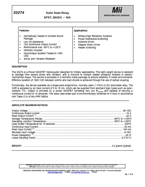
53274 RECOMMENDED OPERATING CONDITIONS: Parameter Output Voltage Continuous Output Current Input Current (on) Input Voltage (off) Operating Case Temperature ELECTRICAL SPECIFICATIONS (Pre-Irradiation) TC = -55°C to +125°C unless otherwise specified Parameter Sym. Min. Typ.* Max. Units Test Conditions IF = 15 mA IO = 10 A Pulse width = 15 ms Duty cycle ≤ 1% VF = 1 VDC VO = 90 VDC IF = 10 mA IR = 10 µA RH ≤ 45%, t = 5 s VI-O = 1000 VDC TC = 25°C IF = 15 mA IO = 10 A Pulse width = 15 ms Duty cycle ≤ 1% 4, 5 Figures 3, 4 Figures 3, 5 6, Figure 3 Notes Symbol VO (OFF) IO (ON) IF (ON) VF (OFF) TC 5 0 -55 Min. Max. 90 10 20 1 125 Units VDC A mA VDC °C Solid State Relay SPST, 90VDC – 10A
7432中文资料
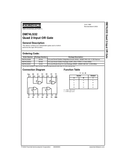
© 2000 Fairchild Semiconductor Corporation DS006361June 1986Revised March 2000DM74LS32 Quad 2-Input OR GateDM74LS32Quad 2-Input OR GateGeneral DescriptionThis device contains four independent gates each of which performs the logic OR function.Ordering Code:Devices also available in T ape and Reel. Specify by appending the suffix letter “X” to the ordering code.Connection Diagram Function TableY = A + B H = HIGH Logic Level L = LOW Logic LevelOrder Number Package NumberPackage DescriptionDM74LS32M M14A 14-Lead Small Outline Integrated Circuit (SOIC), JEDEC MS-120, 0.150 Narrow DM74LS32SJ M14D 14-Lead Small Outline Package (SOP), EIAJ TYPE II, 5.3mm Wide DM74LS32NN14A14-Lead Plastic Dual-In-Line Package (PDIP), JEDEC MS-001, 0.300 WideInputs OutputA B Y L L L L H H H L H HHH 2D M 74L S 32Absolute Maximum Ratings (Note 1)Note 1: The “Absolute Maximum Ratings” are those values beyond which the safety of the device cannot be guaranteed. The device should not be operated at these limits. The parametric values defined in the Electrical Characteristics tables are not guaranteed at the absolute maximum ratings.The “Recommended Operating Conditions” table will define the conditions for actual device operation.Recommended Operating ConditionsElectrical Characteristicsover recommended operating free air temperature range (unless otherwise noted)Note 2: All typicals are at V CC = 5V, T A = 25°C.Note 3: Not more than one output should be shorted at a time, and the duration should not exceed one second.Switching Characteristicsat V CC = 5V and T A = 25°CSupply Voltage 7V Input Voltage7VOperating Free Air Temperature Range 0°C to +70°C Storage Temperature Range−65°C to +150°CSymbol ParameterMin Nom Max Units V CC Supply Voltage4.7555.25V V IH HIGH Level Input Voltage 2V V IL LOW Level Input Voltage 0.8V I OH HIGH Level Output Current −0.4mA I OL LOW Level Output Current 8mA T AFree Air Operating Temperature70°CSymbol ParameterConditionsMinTyp Max Units (Note 2)V I Input Clamp Voltage V CC = Min, I I = −18 mA −1.5V V OH HIGH Level V CC = Min, I OH = Max 2.73.4VOutput Voltage V IH = Min V OLLOW Level V CC = Min, I OL = Max0.350.5Output VoltageV IL = MaxVI OL = 4 mA, V CC = Min 0.250.4I I Input Current @ Max Input Voltage V CC = Max, V I = 7V 0.1mA I IH HIGH Level Input Current V CC = Max, V I = 2.7V 20µA I IL LOW Level Input Current V CC = Max, V I = 0.4V −0.36mA I OS Short Circuit Output Current V CC = Max (Note 3)−20−100mA I CCH Supply Current with Outputs HIGH V CC = Max 3.1 6.2mA I CCLSupply Current with Outputs LOWV CC = Max4.99.8mAR L = 2 k ΩSymbol ParameterC L = 15 pFC L = 50 pFUnitsMinMax Min Max t PLH Propagation Delay Time 311415ns LOW-to-HIGH Level Output t PHLPropagation Delay Time 311415ns HIGH-to-LOW Level OutputDM74LS32Physical Dimensions inches (millimeters) unless otherwise noted14-Lead Small Outline Integrated Circuit (SOIC), JEDEC MS-120, 0.150 NarrowPackage Number M14A 4D M 74L S 32Physical Dimensionsinches (millimeters) unless otherwise noted (Continued)14-Lead Small Outline Package (SOP), EIAJ TYPE II, 5.3mm WidePackage Number M14D5DM74LS32 Quad 2-Input OR GatePhysical Dimensions inches (millimeters) unless otherwise noted (Continued)14-Lead Plastic Dual-In-Line Package (PDIP), JEDEC MS-001, 0.300 WidePackage Number N14AFairchild does not assume any responsibility for use of any circuitry described, no circuit patent licenses are implied and Fairchild reserves the right at any time without notice to change said circuitry and specifications.LIFE SUPPORT POLICYFAIRCHILD’S PRODUCTS ARE NOT AUTHORIZED FOR USE AS CRITICAL COMPONENTS IN LIFE SUPPORT DEVICES OR SYSTEMS WITHOUT THE EXPRESS WRITTEN APPROVAL OF THE PRESIDENT OF FAIRCHILD SEMICONDUCTOR CORPORATION. As used herein:1.Life support devices or systems are devices or systems which, (a) are intended for surgical implant into the body, or (b) support or sustain life, and (c) whose failure to perform when properly used in accordance with instructions for use provided in the labeling, can be rea-sonably expected to result in a significant injury to the user.2. A critical component in any component of a life support device or system whose failure to perform can be rea-sonably expected to cause the failure of the life support device or system, or to affect its safety or effectiveness.。
R5432V规格书中文版
-4-
R5432VxxxXX
■框图(R5432VxxxBA)
VC1
CB1
CB C ircuit-1
VC2
CB2
CB C ircuit-2
VC3
CB3
CB C ircuit-3
VC4
CB4
CB C ircuit-4
VC5
CB5
CB C ircuit-5
VSS
V nochg1
V nochg2
V nochg3
-1-
R5432VxxxXX
■特征
●采用高耐压工艺・・・・・・・・・・・・・・・・・ 最大耐压值
30V
●消费电流・・・・・・・・・・・・・・・・・・・・・・・ 通常状态、5 节时
12.0μA 典型值
●检测电压精度・・・・・・・・・・・・・・・・・・・ 过充电检测精度
±25mV(25℃)
过放电检测精度
过放电检测延迟时间 放电过电流检测延迟时间1 放电过电流检测延迟时间2 充电过电流检测延迟时间
由外接电容 CCT1 设定 由外接电容 CCT2 设定 由外接电容 CCT2 设定
8ms
短路检测延迟时间
300μs
●0V电池充电・・・・・・・・・・・・・・・・・・・・・允许充电
●外接电阻检测过电流・・・・・・・・・・・・・ 放电过电流、充电过电流、短路都通过外部电阻检出。
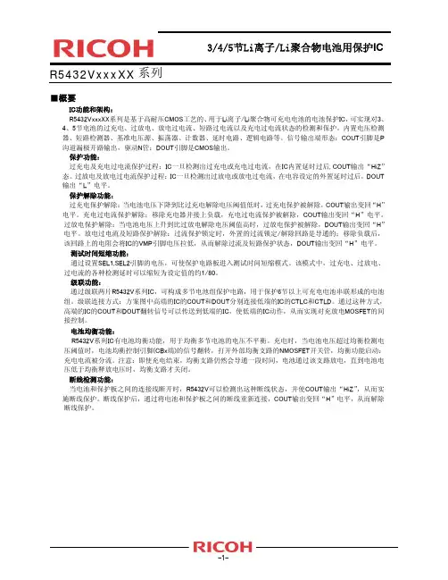
3/4/5节Li离子/Li聚合物电池用保护IC
R5432VxxxXX 系列
■概要
IC功能和架构: R5432VxxxXX系列是基于高耐压CMOS工艺的、用于Li离子/Li聚合物可充电电池的电池保护IC,可实现对3、 4、5节电池的过充电、过放电、放电过电流、短路过电流以及充电过电流状态的检测和保护。内置电压检测 器、短路检测器、基准电压源、振荡器、计数器、延时电路、逻辑电路等。信号输出端形态:COUT引脚是P 沟道漏极开路输出,驱动N管;DOUT引脚是CMOS输出。 保护功能: 过充电及充电过电流保护过程:IC一旦检测出过充电或充电过电流,在IC内置延时过后, COUT输出“HiZ” 态。过放电及放电过电流保护过程:IC一旦检测出过放电或放电过电流,在电容设定的外置延时过后,DOUT 输出“L”电平。 保护解除功能: 过充电保护解除:当电池电压下降到比过充电解除电压阈值低时,过充电保护被解除,COUT输出变回“H” 电平。充电过电流保护解除:移除充电器并接上负载,充电过电流保护被解除,COUT输出变回“H”电平。 过放电保护解除:当电池电压上升到比过放电解除电压阈值高时,过放电保护被解除,DOUT输出变回“H” 电平。放电过电流及短路保护解除:过流保护锁定时,外置的过流锁定/解除回路是导通的;移除负载后, 该回路上的电阻会将IC的VMP引脚电压拉低,从而解除过流及短路保护状态,DOUT输出变回“H”电平。 测试时间短缩功能: 通过设置SEL1,SEL2引脚的电压,可使保护电路板进入测试时间短缩模式。该模式中,过充电、过放电、 过电流的各种检测延时可以缩短为设定值的约1/80。 级联功能: 通过级联两片R5432V系列IC,可构成多节电池组保护电路,用于保护6节以上可充电电池串联形成的电池 组。级联连接方式:方案图中高端的IC的COUT和DOUT分别连接低端的IC的CTLC和CTLD。通过这种方式, 高端的IC的COUT和DOUT翻转信号可以传送到低端的IC,使低端的IC动作,从而实现对充放电MOSFET的间 接控制。 电池均衡功能: R5432V系列IC有电池均衡功能,用于均衡多节电池的电压不平衡。充电时,当电池电压超过均衡检测电 压阈值时,电池均衡控制引脚(CBx端)的信号翻转,打开外部均衡支路的NMOSFET开关管,均衡功能启动: 充电电流被分流。注意:即使充电结束,均衡支路仍然会导通一段时间,电池通过该支路放电,直到电池电 压低于均衡释放电压时,均衡支路才关闭。 断线检测功能: 当电池和保护板之间的连接线断开时,R5432V可以检测出这种断线状态,并使COUT输出“HiZ”,从而实 施断线保护。断线保护后,通过将电池和保护板之间的断线重新连接,COUT输出变回“H”电平,从而解除 断线保护。
7432-5432四二输入或门
54/7432四2输入或门简要说明32为四组2输入端或门(正逻辑),共有54/7432、54/74S32、54/74LS32三种线路结构型式,其主要电特性的典型值如下:型号t PLH t phl P D96mW14ns54/7432 10ns4ns140mW 54/74S32 4ns20mW14ns54/74LS32 14ns引出端符号1A-4A输入端1B-4B输入端1Y-4Y输出端逻辑图双列直插封装极限值电源电压 (7V)输入电压54/7432、54/74S32………………………………. 5.5V54/74LS32 (7V)工作环境温度-55~125℃…………………………………………….54XXX0~70℃74XXX………… ………………………………存储温度 …………………………………………. -65~150℃功能表:推荐工作条件:5432/7432 54S32/74S32 54LS32/74LS32最小 额定 最大 最小额定最大 最小额定 最大单位54 4.5 5 5.5 4.5 5 5.5 4.5 5 5.5 电源电压VCC 74 4.75 5 5.25 4.75 5 5.25 4.75 5 5.25V 输入高电平电压V iH2 2 2 V 540.8 0.8 0.7 输入低电平电压V iL74 0.8 0.8 0.8 V 输出高电平电流I OH -800 -1000 -400 µA 5416 20 4 输出低电平电流I OL74 16 20 8 mA静态特性(TA 为工作环境温度范围)‘32 ‘S32 ‘LS32 参 数测 试 条 件【1】最小最大最小最大最小 最大单位I ik =-12mA -1.5V IK 输入嵌位电压 Vcc=最小I ik =-18mA -1.2 -1.5V 54 2.4 2.5 2.5 V OH 输出高电平电压 Vcc =最小V IH =2V ,I OH =最大74 2.4 2.7 2.7 V 54 0.4 0.5 0.4 V OL 输出低电平电压 Vcc=最小,V IL =最大,I OL =最大74 0.4 0.5 0.5 V V I =5.5V 1 1 I I 最大输入电压时输入电流Vcc =最大 V I =7V 0.1 mA V IH =2.4V 40 I IH 输入高电平电流 Vcc =最大V IH =2.7V 50 20µA V IL =0.4V -1.6 -0.4I IL 输入低电平电流 Vcc =最大V IL =0.5V -2mA 54 -20 -55 -40 -100-20 -100I OS 输出短路电流 Vcc =最大74 -18 -55 -40 -100-20 -100mA I CCH 输出高电平时电源电流 Vcc =最大22 32 6.2 mA I CCL 输出低电平时电源电流 Vcc =最大38 68 9.8 mA[1]: 测试条件中的“最小”和“最大”用推荐工作条件中的相应值。
CS42324中文资料
10-In, 6-Out, 2Vrms Audio CODECD/A FeaturesDual 24-bit Stereo DACs Multi-bit Delta-Sigma Modulator 100dB Dynamic Range (A-Wtd) -90dB THD+N Integrated Line Driver– 2 Vrms Output–Single-Ended OutputsUp to 96kHz Sampling Rates Stereo 7:1 Output Multiplexer Volume Control with Soft Ramp–0.5dB Step Size–Zero Crossing Click-Free Transitions Selectable Serial Audio Interface Formats –Left- or Right-Justified, Up to 24-bit –I²S Up to 24-bitSelectable 50/15 μs De-Emphasis Internal Analog MuteControl Output for External Muting Popguard ® TechnologyA/D FeaturesMulti-bit Delta-Sigma Modulator 24-bit ConversionUp to 96kHz Sampling Rates 95dB Dynamic Range (A-Wtd) -88dB THD+NStereo 5:1 Input MultiplexerDigital Volume Control with Soft Ramp–0.5dB Step SizeSelectable Serial Audio Interface Formats–Left-Justified –I²SHigh-Pass Filter or DC Offset Calibration See System Features , General Description , and Order-ing information on page 2.CS42324System FeaturesDirect Interface with 1.8 V to 3.3 V Logic LevelsSupports Asynchronous Serial Port Operation –Two Independent Clock Domains–ADC, DAC1, and DAC2 can beIndependently Assigned to the Two ClockDomains–Each Serial Port Supports Master or Slave OperationInternal Digital Loopback+3.3V Analog Power Supply+3.3V Digital Power Supply+9 V to +12 V High-Voltage Power SupplyHardware or Software Mode Configuration –Supports I²C® and SPI™ Software Interface General DescriptionThe CS42324 is a highly integrated stereo audio CODEC. The CS42324 performs stereo analog-to-digital (A/D) and up to four channels of digital-to-analog (D/A) conversion of up to 24-bit serial values at sample rates up to 96kHz.A 5:1 stereo input multiplexer is included for selecting between line-level inputs. The output of the input multi-plexer is followed by an advanced 3rd-order, multi-bit delta-sigma modulator and digital filtering/decimation. Sampled data is transmitted by the serial audio inter-face at rates from 4kHz to 96kHz, in either Slave or Master Mode.The D/A converter is based on a 5th-order multi-bit del-ta-sigma modulator with an ultra-linear low-pass filter and offers a volume control that operates with a 0.5dB step size. It incorporates selectable soft ramp and zero crossing transition functions to eliminate clicks and pops.An integrated 7:1 stereo output multiplexer on each of the three stereo 2 Vrms line-level outputs is used to se-lect any of the 5 stereo analog inputs, for analog bypass support, or the outputs of the 2 internal DACs. Each 2Vrms output can be muted with the selectable analog mute function.Standard 50/15μs de-emphasis is available for a 44.1kHz sample rate for compatibility with digital audio programs mastered using the 50/15μs pre-emphasis technique.Integrated digital level translators allow easy interfacing between the CS42324 and other devices operating over a wide range of logic levels.The CS42324 is available in a 48-pin LQFP package in Commercial (-40°C to +85°C) and Automotive (-40°C to +105°C) grades. The CDB42324 Customer Demonstra-tion board is also available for device evaluation and implementation suggestions. Please refer to “Ordering information” on page71 for complete details.TABLE OF CONTENTS1. PIN DESCRIPTIONS (8)1.1 Software Mode (8)1.2 Hardware Mode (10)1.3 Digital I/O Pin Characteristics (12)2. CHARACTERISTICS AND SPECIFICATIONS (13)RECOMMENDED OPERATING CONDITIONS (13)ABSOLUTE MAXIMUM RATINGS (13)DAC ANALOG CHARACTERISTICS - COMMERCIAL (-CQZ) (14)DAC ANALOG CHARACTERISTICS - AUTOMOTIVE (-DQZ) (15)DAC COMBINED INTERPOLATION & ON-CHIP ANALOG FILTER RESPONSE (16)ADC ANALOG CHARACTERISTICS - COMMERCIAL (-CQZ) (17)ADC ANALOG CHARACTERISTICS - AUTOMOTIVE (-DQZ) (18)ADC DIGITAL FILTER CHARACTERISTICS (19)ANALOG PASS-THRU CHARACTERISTICS (20)DC ELECTRICAL CHARACTERISTICS (21)DIGITAL INTERFACE CHARACTERISTICS (21)SWITCHING CHARACTERISTICS - SERIAL AUDIO (22)SWITCHING CHARACTERISTICS - SERIAL AUDIO (CONT.) (23)SWITCHING CHARACTERISTICS - SOFTWARE MODE - I²C FORMAT (24)SWITCHING CHARACTERISTICS - SOFTWARE MODE - SPI FORMAT (25)3. TYPICAL CONNECTION DIAGRAMS (26)4. APPLICATIONS (28)4.1 System Clocking (28)4.1.1 Master Clock (28)4.1.2 Synchronous / Asynchronous Mode (29)4.2 Serial Port Operation (29)4.2.1 Master Mode (30)4.2.2 Slave Mode (30)4.2.3 ADC, DAC1, and DAC2 clock selection (31)4.2.4 High-Impedance Digital Output (31)4.2.5 Digital Interface Formats (32)4.2.6 Synchronization of Multiple Devices (32)4.3 Analog-to-Digital Data Path (33)4.3.1 ADC Analog Input Multiplexer (33)4.3.2 ADC Description (33)4.3.3 High-Pass Filter and DC Offset Calibration (34)4.3.4 Digital Attenuation Control (34)4.4 Digital-to-Analog Data Path (34)4.4.1 Digital Volume Control (34)4.4.2 Mono Channel Mixer (34)4.4.3 De-Emphasis Filter (35)4.4.4 Internal Digital Loopback (35)4.4.5 DAC Description (35)4.4.6 Analog Output Multiplexer (36)4.4.7 Output Transient Control (36)4.4.8 Mute Control (37)4.5 Initialization (37)4.5.1 Determining Hardware or Software Mode (37)4.5.2 Hardware Mode Start-Up (37)4.5.3 Software Mode Start-Up (38)4.5.4 Initialization Flow Chart (39)4.6 Device Control (40)4.6.2 Software Mode - I²C Control Port (41)4.6.3 Software Mode - SPI Control Port (42)4.6.4 Memory Address Pointer (MAP) (43)4.7 Interrupts and Overflow (43)5. REGISTER QUICK REFERENCE (44)6. REGISTER DESCRIPTION (46)6.1 Device I.D. and Revision Register (Address 00h) (Read Only) (46)6.1.1 Device I.D. (Read Only) (46)6.1.2 Chip Revision (Read Only) (46)6.2 Mute Control (Address 01h) (46)6.2.1 System MCLK Source (46)6.2.2 Mute DAC2 Left-Channel (46)6.2.3 Mute DAC2 Right-Channel (47)6.2.4 Mute DAC1 Left-Channel (47)6.2.5 Mute DAC1 Right-Channel (47)6.2.6 Mute ADC Left-Channel (47)6.2.7 Mute ADC Right-Channel (47)6.3 Operational Control (Address 02h) (47)6.3.1 Global Power-Down (47)6.3.2 INT Pin High/Low Active (INT_H/L) (48)6.3.3 Freeze (48)6.3.4 Tri-State SDOUT (48)6.3.5 Tri-State Serial Port 1 (48)6.3.6 Tri-State Serial Port 2 (49)6.4 Serial Port 1 Control (Address 03h) (49)6.4.1 Serial Port 1 Master/Slave Select (49)6.4.2 Serial Port 1 Speed Mode (49)6.4.3 MCLK1 Divider (49)6.4.4 Serial Port 1 MCLK source (49)6.5 Serial Port 2 Control (Address 04h) (50)6.5.1 Serial Port 2 Master/Slave Select (50)6.5.2 Serial Port 2 Speed Mode (50)6.5.3 MCLK2 Divider (50)6.5.4 Serial Port 2 MCLK Source (50)6.6 ADC Clocking (Address 06h) (50)6.6.1 ADC MCLK Source (50)6.6.2 ADC Serial Port Source (51)6.6.3 ADC Digital Interface Format (ADC_DIF) (51)6.7 DAC1 Clocking (Address 07h) (51)6.7.1 DAC1 MCLK Source (51)6.7.2 DAC1 Serial Port Source (51)6.7.3 DAC1 Digital Interface Format (DAC1_DIF) (51)6.8 DAC2 Clocking (Address 08h) (52)6.8.1 DAC2 MCLK Source (52)6.8.2 DAC2 Serial Port Source (52)6.8.3 DAC2 Digital Interface Format (DAC2_DIF) (52)6.9 ADC Control (Address 0Ah) (52)6.9.1 ADC High-Pass Filter Freeze (52)6.9.2 ADC Soft Ramp Control (52)6.9.3 Analog Input Selection (53)6.10 DAC1 Control (Address 0Bh) (53)6.10.1 DAC1 De-Emphasis Control (53)6.10.2 DAC1 Single Volume Control (53)6.10.4 DAC1 Zero Cross Control (54)6.10.5 DAC1 Loop-Back (54)6.10.6 DAC1 Invert Signal Polarity (54)6.10.7 DAC1 Channel Mixer (54)6.11 DAC2 Control (Address 0Ch) (55)6.11.1 DAC2 De-Emphasis Control (55)6.11.2 DAC2 Single Volume Control (55)6.11.3 DAC2 Soft Ramp Control (55)6.11.4 DAC2 Zero Cross Control (55)6.11.5 DAC2 Loop-Back (56)6.11.6 DAC2 Invert Signal Polarity (56)6.11.7 DAC2 Channel Mixer (56)6.12 AOUT1 Control (Address 0Dh) (56)6.12.1 External Mute Control Pin (56)6.12.2 AOUT1 Select (56)6.13 AOUT2 Control (Address 0Eh) (57)6.13.1 External Mute Control Pin (57)6.13.2 AOUT2 Select (57)6.14 AOUT3 Control (Address 0Fh) (57)6.14.1 External Mute Control Pin (57)6.14.2 AOUT3 Select (58)6.15 ADCx Volume Control: ADCA (Address 10h) & ADCB (Address 11h) (58)6.16 DAC1x Volume Control: DAC1A (Address 12h) & DAC1B (Address 13h) (58)6.17 DAC2x Volume Control: DAC1A (Address 14h) & DAC1B (Address 15h) (59)6.18 Interrupt Mode (Address 16h) (59)6.19 Interrupt Mask (Address 17h) (59)6.19.1 DAC2 Auto Mute Left Mask (DAC2_AMUTELM) (60)6.19.2 DAC2 Auto Mute Right Mask (DAC2_AMUTERM) (60)6.19.3 DAC1 Auto Mute Left Mask (DAC1_AMUTELM) (60)6.19.4 DAC1 Auto Mute Right Mask (DAC1_AMUTELM) (60)6.19.5 Serial Port 2 Clock Error Mask (SP2_CLKERRM) (60)6.19.6 Serial Port 1 Clock Error Mask (SP1_CLKERRM) (60)6.19.7 ADC Positive Overflow Mask (ADC_OVFLPM) (61)6.19.8 ADC Negative Overflow Mask (ADC_OVFLNM) (61)6.20 Interrupt Status (Address 18h) (Read Only) (61)6.20.1 DAC2 Auto Mute Left Interrupt Status (DAC2_AMUTEL) (61)6.20.2 DAC2 Auto Mute Right Interrupt Status (DAC2_AMUTER) (61)6.20.3 DAC1 Auto Mute Left Interrupt Status (DAC1_AMUTEL) (62)6.20.4 DAC1 Auto Mute Right Interrupt Status (DAC1_AMUTEL) (62)6.20.5 Serial Port 2 Clock Error Interrupt Status (SP2_CLKERR) (62)6.20.6 Serial Port 1 Clock Error Interrupt Status (SP1_CLKERR) (62)6.20.7 ADC Positive Overflow Interrupt Bit (ADC_OVFLP) (62)6.20.8 ADC Negative Overflow Interrupt Bit (ADC_OVFLN) (63)7. GROUNDING AND POWER SUPPLY DECOUPLING (64)8. ADC FILTER PLOTS (65)9. DAC DIGITAL FILTER RESPONSE PLOTS (67)10. PARAMETER DEFINITIONS (69)11. PACKAGE DIMENSIONS (70)THERMAL CHARACTERISTICS AND SPECIFICATIONS (70)12. ORDERING INFORMATION (71)13. REVISION HISTORY (71)LIST OF FIGURESFigure 1.Equivalent Analog Output Load (16)Figure 2.Maximum Analog Output Loading (16)Figure 3.Serial Input Timing (22)Figure 4.Serial Output Timing (23)Figure 5.Software Mode Timing - I²C Format (24)Figure 6.Software Mode Timing - SPI Mode (25)Figure 7.Typical Connection Diagram - Software Mode (26)Figure 8.Typical Connection Diagram - Hardware Mode (27)Figure 9.Serial Port Topology (29)Figure 10.Master Mode Clock Generation (30)Figure 11.Converter Clocking (31)Figure 12.Tri-State Serial Port (31)Figure 13.Left-Justified up to 24-Bit Data (32)Figure 14.I²S up to 24-Bit Data (32)Figure 15.Right-Justified 16-Bit Data, Right-Justified 24-Bit Data (32)Figure 16.Analog Input Architecture (33)Figure 17.De-Emphasis Curve (35)Figure 18.Analog Output Architecture (36)Figure 19.Initialization Flow Chart (39)Figure 20.Software Mode Timing, I²C Write (41)Figure 21.Software Mode Timing, I²C Read (41)Figure 22.Software Mode Timing, SPI Mode (43)Figure 23.Single-Speed Mode Stopband Rejection (65)Figure 24.Single-Speed Mode Transition Band (65)Figure 25.Single-Speed Mode Transition Band (Detail) (65)Figure 26.Single-Speed Mode Passband Ripple (65)Figure 27.Double-Speed Mode Stopband Rejection (65)Figure 28.Double-Speed Mode Transition Band (65)Figure 29.Double-Speed Mode Transition Band (Detail) (66)Figure 30.Double-Speed Mode Passband Ripple (66)Figure 31.Single-Speed Stopband Rejection (67)Figure 32.Single-Speed Transition Band (67)Figure 33.Single-Speed Transition Band (detail) (67)Figure 34.Single-Speed Passband Ripple (67)Figure 35.Double-Speed Stopband Rejection (67)Figure 36.Double-Speed Transition Band (67)Figure 37.Double-Speed Transition Band (detail) (68)Figure 38.Double-Speed Passband Ripple (68)Figure 39.Quad-Speed Stopband Rejection (68)Figure 40.Quad-Speed Transition Band (68)Figure 41.Quad-Speed Transition Band (detail) (68)Figure 42.Quad-Speed Passband Ripple (68)LIST OF TABLESTable 1. I/O Power Rails (12)Table 2. Speed Modes (28)Table 3. Single-Speed Mode Common Clock Frequencies (28)Table 4. Double-Speed Mode Common Clock Frequencies (28)Table 5. M1 and M0 Mode Pins in Hardware Mode (29)Table 6. Slave Mode SCLK/LRCK Ratios (30)Table 7. MCLKx to LRCKx Ratios (30)Table 8. Hardware Mode Interface Format Control (32)Table 9. Hardware Mode Feature Summary (40)Table 10. Freeze-able Bits (48)1.PIN DESCRIPTIONS1.1Software ModePin Name #Pin DescriptionSDA/CDOUT1I²C Format SDA (Input/Output ) - Acts as an input/output data pin. An external pull-up resistor is required for I²C control port operation.SPI Format CDOUT (Output ) - Acts as an output only data pin.SCL/CCLK 2I²C Format, SCL (Input ) – Serial clock for the serial control port. An external pull-up resistor is required for I²C control port operation.SPI Format, CCLK (Input ) – Serial clock for the serial control port.AD0/CS 3I²C Format, AD0 (Input ) - Forms the device address input AD[0].SPI Format, CS (Input ) - Acts as the active low chip select input.AD1/CDIN 4I²C Format, AD1 (Input ) - Forms the device address input AD[1].SPI Format, CDIN (Input ) - Becomes the input data pin.INT 5Interrupt (Output ) - Indicates an interrupt condition has occurred.FILT+6FILT+ (Output ) - Full-scale reference voltage for ADC.VCMADC 7ADC Common-Mode Voltage (Output ) - Filter connections for the ADC internal quiescent refer-ence voltage.GND 8Analog Ground (Input ) - Analog ground reference.VA 9Analog Power (Input) - Positive power for the internal analog section.VBIAS 10Bias Voltage (Output ) - Positive reference voltage for the internal DAC.MUTEC111Mute Control 1 (Output ) - Active-low mute output can drive external circuitry to eliminate the clicks and pops associated with any single-rail output. This pin will become a high-impedance out-put during power-down mode or when an invalid MCLK to LRCK ratio is detected.SCL/CCLK G N D HS C L K 1AD0/CS AD1/CDININT SDA/CDOUT FILT+VCMADCGND VA VBIAS MUTEC1MUTEC2V A _HA O U T 1BA O U T 2AA O U T 2BA O U T 3AA O U T 3BM U T E C 3V C M B U FV C M D A CV A _HA O U T 1AS D I N 2M C L K 1L R C K 1V DG N DV LS D O U TC L K 2L R C K 2M C L K 2D I N 1MUTEC212Mute Control 2 (Output) - Active-low mute output can drive external circuitry to eliminate the clicks and pops associated with any single-rail output. This pin will become a high-impedance out-put during power-down mode or when an invalid MCLK to LRCK ratio is detected.MUTEC313Mute Control 3 (Output) - Active-low mute output can drive external circuitry to eliminate the clicks and pops associated with any single-rail output. This pin will become a high-impedance out-put during power-down mode or when an invalid MCLK to LRCK ratio is detected.VCMBUF14VCMBUF (Output) -Internally buffered VCMDACVCMDAC15DAC Common-Mode Voltage (Output)-Filter connections for the DAC internal quiescent refer-ence voltage.VA_H 1618Analog High Voltage Power (Input)-Positive power for the internal output buffer section.GNDH17Analog Ground (Input) - Ground reference for high-voltage section.AOUT1A, AOUT1B AOUT2A, AOUT2B AOUT3A, AOUT3B 19, 2021, 2223, 24DAC Analog Audio Outputs (Output) - The full-scale output level is specified in the DAC Analog Characteristics specification table.AIN5B, AIN5A AIN4B, AIN4A AIN3B, AIN3A AIN2B, AIN2A AIN1B, AIN1A 25, 2627, 2829, 3031, 3233, 34Stereo Analog Inputs 1-5 (Input)-The full-scale input level is specified in the ADC Analog Char-acteristics specification table.RST35Reset (Input) - The device enters a low-power mode when this pin is driven low. OVFL36ADC Overflow (Output) -Indicates an ADC overflow condition is present.SDIN2 SDIN13738Serial Audio Data Input (Input) - Input for two’s complement serial audio data.MCLK239Master Clock 2 (Input) - Optional asynchronous clock source for the DAC’s delta-sigma modula-tors.LRCK240Serial Port 2 Left/Right Clock(Input/Output) - Determines which channel, Left or Right, is cur-rently active on the serial audio input data line.SCLK241Serial Port 2 Serial Bit Clock (Input/Output)-Serial bit clock for serial audio interface 2. VD42Digital Power (Input) -Positive power for the internal digital section.GND43Digital Ground (Input) - Ground reference for the internal digital section.VL44Digital Interface Power (Input) -Determines the required signal level for the control and serial port interfaces as shown in “I/O Power Rails” on page12. Refer to the“Recommended Operating Conditions” on page13 for appropriate voltages.SDOUT45Serial Audio Data Output (Output) -Output for two’s complement serial audio data. SCLK146Serial Port 1 Serial Bit Clock (Input/Output)-Serial bit clock for serial audio interface 1.LRCK147Serial Port 1 Left/Right Clock(Input/Output) - Determines which channel, Left or Right, is cur-rently active on the serial audio output data line.MCLK148Master Clock 1 (Input) - Clock source for the ADC’s delta-sigma modulators. By default, this sig-nal also clocks the DAC’s delta-sigma modulators.1.2Hardware ModePin Name#Pin DescriptionM0, M11, 2Mode Selection (Input) - Determines the operational mode of the device.MDIV3MCLK Divider (Input) - Setting this pin high places a divide-by-2 circuit in the MCLK path to the core device circuitry.MUTE4MUTE (Input) -Engages the internal digital mute and activates the MUTECx pinsDIF5DIF (Input) -Sets the serial audio interface format. Setting DIF high selects I²S audio format and low selects LJ audio format.FILT+6FILT+ (Output) -Full-scale reference voltage for ADC.VCMADC7ADC Common-Mode Voltage (Output)-Filter connections for the ADC internal quiescent refer-ence voltage.GND8Analog Ground (Input)-Analog ground reference.VA9Analog Power (Input)-Positive power for the internal analog section. VBIAS10Bias Voltage (Output)-Positive reference voltage for the internal DAC.MUTEC111Mute Control 1 (Output) - Active-low mute output can drive external circuitry to eliminate the clicks and pops associated with any single-rail output. This pin will become a high-impedance out-put during power-down mode or when an invalid MCLK to LRCK ratio is detected.MUTEC212Mute Control 2 (Output) - Active-low mute output can drive external circuitry to eliminate the clicks and pops associated with any single-rail output. This pin will become a high-impedance out-put during power-down mode or when an invalid MCLK to LRCK ratio is detected.OVFLRSTAIN1AAIN1BAIN2AAIN2BAIN3AAIN3BAIN4AAIN4BAIN5AAIN5BM1MDIVMUTEDIFM0FILT+VCMADCGNDVAVBIAS MUTEC1 MUTEC2SCLK1SDIN2 MCLK1LRCK1VDGNDVLSDOUTSCLK2LRCK2MCLK2SDIN1GNDHVA_HAOUT1BAOUT2AAOUT2BAOUT3AAOUT3B MUTEC3VCMBUFVCMDACVA_HAOUT1AMUTEC313Mute Control 3 (Output) - Active-low mute output can drive external circuitry to eliminate the clicks and pops associated with any single-rail output. This pin will become a high-impedance out-put during power-down mode or when an invalid MCLK to LRCK ratio is detected.VCMBUF14VCMBUF (Output) -Internally buffered VCMDACVCMDAC15DAC Common-Mode Voltage (Output)- Filter connections for the DAC internal quiescent refer-ence voltage.VA_H16, 18Analog High Voltage Power (Input)-Positive power for the internal output buffer section. GNDH17Analog Ground (Input) - Ground reference for high-voltage section.AOUT1A, AOUT1B AOUT2A, AOUT2B AOUT3A, AOUT3B 19, 2021, 2223, 24DAC Analog Audio Outputs (Output) - The full-scale output level is specified in the DAC Analog Characteristics specification table.AIN5B, AIN5A AIN4B, AIN4A AIN3B, AIN3A AIN2B, AIN2A AIN1B, AIN1A 25, 2627, 2829, 3031, 3233, 34Stereo Analog Inputs 1-5 (Input)-The full-scale input level is specified in the ADC Analog Char-acteristics specification table.RST35Reset (Input) - The device enters a low-power mode when this pin is driven low. OVFL36ADC Overflow (Output) -Indicates an ADC overflow condition is present.SDIN2 SDIN13738Serial Audio Data Input (Input) - Input for two’s complement serial audio data.MCLK239Master Clock 2 (Input) - Optional asynchronous clock source for the DAC’s delta-sigma modula-tors.LRCK240Serial Port 2 Left/Right Clock(Input/Output) - Determines which channel, Left or Right, is cur-rently active on the serial audio input data line.SCLK241Serial Port 2 Serial Bit Clock (Input/Output)-Serial bit clock for serial audio interface 2. VD42Digital Power (Input) -Positive power for the internal digital section.GND43Digital Ground (Input) - Ground reference for the internal digital section.VL44Digital Interface Power (Input) -Determines the required signal level for the control and serial port interfaces as shown in “I/O Power Rails” on page12. Refer to the“Recommended Operating Conditions” on page13 for appropriate voltagesSDOUT45Serial Audio Data Output (Output) -Output for two’s complement serial audio data. SCLK146Serial Port 1 Serial Bit Clock (Input/Output)-Serial bit clock for serial audio interface 1.LRCK147Serial Port 1 Left Right/Clock(Input/Output) - Determines which channel, Left or Right, is cur-rently active on the serial audio output data line.MCLK148Master Clock 1 (Input) - Clock source for the ADC’s delta-sigma modulators. By default, this sig-nal also clocks the DAC’s delta-sigma modulators.1.3Digital I/O Pin CharacteristicsThe logic level for each input should adhere to the corresponding power rail and should not exceed the max-imum ratings.Power SupplyPinNumberPin Name I/O Driver ReceiverSoftware ModeVL 1SDACDOUTInput/OutputHi-Z/Output1.8 V - 3.3 V, Open Drain1.8 V - 3.3 V, CMOS1.8 V - 3.3 V, with Hysteresis 2SCLCCLKInput- 1.8 V - 3.3 V, with Hysteresis 3AD0CSInput- 1.8 V - 3.3 V, with Hysteresis 4AD1CDINInput- 1.8 V - 3.3 V, with Hysteresis 5INT Output 1.8 V - 3.3 V, Open Drain 1.8 V - 3.3 V, with HysteresisHardware ModeVL 1M0Input- 1.8 V - 3.3 V, with Hysteresis 2M1Input- 1.8 V - 3.3 V, with Hysteresis 3MDIV Input- 1.8 V - 3.3 V, with Hysteresis 4MUTE Input- 1.8 V - 3.3 V, with Hysteresis 5DIF Input- 1.8 V - 3.3 V, with HysteresisAll ModesVL 35RST Input- 1.8 V - 3.3 V 4740LRCK1LRCK2Input/Output 1.8 V - 3.3 V, CMOS 1.8 V - 3.3 V 4641SCLK1SCLK2Input/Output 1.8 V - 3.3 V, CMOS 1.8 V - 3.3 V 4839MCLK1MCLK2Input- 1.8 V - 3.3 V 3837SDIN1SDIN2Input- 1.8 V - 3.3 V 45SDOUT Output 1.8 V - 3.3 V, CMOS-36OVFL Output 1.8 V - 3.3 V, Open Drain-VA_H 111213MUTEC1MUTEC2MUTEC3Output9.0 V - 12.0 V-Table 1. I/O Power Rails2.CHARACTERISTICS AND SPECIFICATIONS RECOMMENDED OPERATING CONDITIONSGND =GNDH =0V; All voltages with respect to ground.ABSOLUTE MAXIMUM RATINGSGND =GNDH =0 V; All voltages with respect to ground. (Note 1)Notes:1.Operation beyond these limits may result in permanent damage to the device.Normal operation is not guaranteed at these extremes.2.Any pin except supplies. Transient currents of up to ±100mA on the analog input pins will not causeSCR latch-up.ParametersSymbol Min Nom Max Units DC Power Supplies:Analog Digital LogicHigh Voltage AnalogVA VD VL VA_H 3.133.131.718.55 3.33.33.39.0 3.473.473.4712.60V V V V Ambient Operating Temperature (Power Applied)Commercial(-CQZ)Automotive(-DQZ)T A-40-40--+85+105°C °CParameterSymbol Min Max Units DC Power Supplies:Analog Digital LogicHigh Voltage AnalogVA VD VL VA_H -0.3-0.3-0.3-0.3+4.50+4.50+4.50+17.0V V V V Input Current (Note 2)I in -10+10mA Analog Input Voltage V INA GND - 0.3VA_H + 0.3V Digital Input VoltageLogicV IND -0.3VL + 0.4V Ambient Operating Temperature (Power Applied)T A -55+125°C Storage TemperatureT stg-65+150°CTest Conditions (unless otherwise specified): VA = VD = VL = 3.3V, VA_H = 9V, GND =GNDH =0V; T A = 25°C; 997Hz Full-Scale Output Sine Wave. Decoupling capacitors, Filter capacitors, and Recommended output filter as shown in Figure 7 on page 26 and Figure 8 on page 27; Fs =48 kHz or 96kHz; Synchronous Mode; Measurement Bandwidth 10 Hz to 20kHz,Notes:3.One-half LSB of triangular PDF dither added to data.4.See Figures 1 and 2 on page 16. R L and C L reflect the minimum resistance and maximum capacitanceallowed in order to maintain stability in the internal op-amp. C L affects the dominant pole of the internal output amp; increasing C L beyond 100pF can cause the internal op-amp to become unstable.ParameterSymbolMin Typ Max Unit Dynamic Range(Note 3)18 to 24-Bit A-weighted unweighted 16-BitA-weighted unweighted94918885100979390----dB dB dB dB Total Harmonic Distortion + Noise(Note 3)18 to 24-Bit0 dB -20 dB-60 dB 16-Bit0 dB -20 dB -60 dB THD+N -------90-77-37-87-77-37-84-73-33-82-62-22dB dB dB dB dB dB Interchannel Isolation (1kHz)--100-dB DC AccuracyInterchannel Gain Mismatch -0.10.25dB Gain Drift -100-ppm/°C Analog OutputFull-Scale Output Voltage1.92.0 2.1V rms Max current draw from an AOUT pin I OUT-575-μA AC-Load Resistance (Note 4)R L 5--k ΩLoad Capacitance (Note 4)C L --100pF Output ImpedanceZ OUT-50-ΩTest Conditions (unless otherwise specified): VA =3.13V to 3.47V, VD =3.13V to 3.47V, VL =1.71V to 3.47V, VA_H = 8.55V to 12.60V, GND=GNDH=0V; T A = -40° C to +85° C; 997Hz Full-Scale Output Sine Wave. Decoupling capacitors, filter capacitors, and recommended output filter as shown in Figure 7 on page 26 and Fig-ure 8 on page 27; Fs=48 kHz or 96kHz; Synchronous Mode; Measurement Bandwidth 10 Hz to 20kHz,Parameter Symbol Min Typ Max Unit Dynamic Range(Note 3)18 to 24-Bit A-weightedunweighted 16-Bit A-weightedunweighted 90878380100979390----dBdBdBdBTotal Harmonic Distortion + Noise(Note 3)18 to 24-Bit0 dB-20 dB-60 dB 16-Bit0 dB-20 dB-60 dB THD+N-------90-77-37-87-77-37-80-67-27-77-67-27dBdBdBdBdBdBInterchannel Isolation(1kHz)--100-dB DC AccuracyInterchannel Gain Mismatch-0.10.25dB Gain Drift-100-ppm/°C Analog OutputFull-Scale Output Voltage 1.9 2.0 2.1V rms Max current draw from an AOUT pin I OUT-575-μA AC-Load Resistance(Note 4)R L5--kΩLoad Capacitance(Note 4)C L--100pF Output Impedance Z OUT-50-ΩDAC COMBINED INTERPOLATION & ON-CHIP ANALOG FILTER RESPONSENotes:5.Response is clock-dependent and will scale with Fs. Note that the amplitude vs. frequency plots of thisdata (Figures 31 to 42) have been normalized to Fs and can be de-normalized by multiplying the X-axis scale by Fs.6.For Single-Speed Mode, the measurement bandwidth is from StopBand to 3 Fs.For Double-Speed Mode, the measurement bandwidth is from StopBand to 3 Fs.7.De-emphasis is available only in Single-Speed Mode.Parameter (Note 5)SymbolMinTypMaxUnitSingle-Speed Mode Passband (Note 6)to -0.01dB corner to -3dB corner00--.454.499Fs FsFrequency Response (10Hz to 20kHz)-0.01-+0.01dB StopBand0.547--Fs StopBand Attenuation (Note 6)102--dB Group Delaytgd-9.4/Fs -s De-emphasis Error (Note 7) Fs = 44.1 kHz--+/-0.14dBDouble-Speed Mode Passband (Note 6)to -0.01dB corner to -3dB corner00--.43.499Fs Fs Frequency Response (10Hz to 20kHz)-0.01-+0.01dB StopBand.583--Fs StopBand Attenuation (Note 6)80--dB Group Delaytgd- 4.6/Fs-sFigure 1. Equivalent Analog Output Load Figure 2. Maximum Analog Output Loading。
IDT74FCT543TLB中文资料
MILITARY AND COMMERCIAL TEMPERATURE RANGESJANUARY 1995©1995 Integrated Device Technology, Inc.6.17DSC-4203/5The FCT543T/FCT2543T is a non-inverting octal trans-ceiver built using an advanced dual metal CMOS technology.This device contains two sets of eight D-type latches with separate input and output controls for each set. For data flow from A to B, for example, the A-to-B Enable (CEAB ) input must be LOW in order to enter data from A 0–A 7 or to take data from B 0–B 7, as indicated in the Function Table. With CEAB LOW,a LOW signal on the A-to-B Latch Enable (LEAB ) input makes the A-to-B latches transparent; a subsequent LOW-to-HIGH transition of the LEAB signal puts the A latches in the storage mode and their outputs no longer change with the A inputs.With CEAB and OEAB both LOW, the 3-state B output buffers are active and reflect the data present at the output of the A latches. Control of data from B to A is similar, but uses the CEBA , LEBA and OEBA inputs.The FCT2543T has balanced output drive with current limiting resistors. This offers low ground bounce, minimal undershoot and controlled output fall times-reducing the need for external series terminating resistors. FCT2xxxT parts are plug-in replacements for FCTxxxT parts.1•Common features:–Low input and output leakage ≤1µA (max.)–CMOS power levels–True TTL input and output compatibility – V OH = 3.3V (typ.)– V OL = 0.3V (typ.)–Meets or exceeds JEDEC standard 18 specifications –Product available in Radiation Tolerant and Radiation Enhanced versions–Military product compliant to MIL-STD-883, Class B and DESC listed (dual marked)–Available in DIP, SOIC, SSOP, QSOP, CERPACK and LCC packages •Features for FCT543T:–Std., A, C and D speed grades–High drive outputs (-15mA I OH , 64mA I OL )–Power off disable outputs permit “live insertion”•Features for FCT2543T:–Std., A, and C speed grades–Resistor outputs (-15mA I OH , 12mA I OL Com.)(-12mA I OH , 12mA I OL Mil.)–Reduced system switching noiseFAST CMOS OCTAL LATCHED TRANSCEIVERMILITARY AND COMMERCIAL TEMPERATURE RANGES6.172PIN CONFIGURATIONSDIP/SOIC/SSOP/QSOP/CERPACKTOP VIEWGNDA 0A 1A 2VccB 0A 3A 4A 5A 6A 7B 1B 2B 3B 4B 5B 6B 7OEABCEBA LCC TOP VIEWG N N CNC B 1B 2B 3B 4B 5B 6A C E AB B L E A B O E A B 2613 drw 022613 drw 03FUNCTION TABLE (1, 2)For A-to-B (Symmetric with B-to-A)2613 tbl 021.* Before LEAB LOW-to-HIGH TransitionH = HIGH Voltage Level L = LOW Voltage Level— = Don’t Care or Irrelevant2.A-to-B data flow shown; B-to-A flow control is the same, except usingCEBA , LEBA and OEBA .(1)NOTES:1.Stresses greater than those listed under ABSOLUTE MAXIMUM RAT-INGS may cause permanent damage to the device. This is a stress rating only and functional operation of the device at these or any other conditions above those indicated in the operational sections of this specification is not implied. Exposure to absolute maximum rating conditions for extended periods may affect reliability. No terminal voltage may exceed V CC by +0.5V unless otherwise noted.2.Input and V CC terminals only.3.Outputs and I/O terminals only.1. This parameter is measured at characterization but not tested.DC ELECTRICAL CHARACTERISTICS OVER OPERATING RANGEFollowing Conditions Apply Unless Otherwise Specified:NOTES:1.For conditions shown as Max. or Min., use appropriate value specified under Electrical Characteristics for the applicable device type.2.Typical values are at Vcc = 5.0V, +25°C ambient.3.Not more than one output should be shorted at one time. Duration of the short circuit test should not exceed one second.4.The test limit for this parameter is ±5µA at T A = –55°C.5.This parameter is guaranteed but not tested.6.173NOTES:2613 tbl 081.For conditions shown as Max. or Min., use appropriate value specified under Electrical Characteristics for the applicable device type.2.Typical values are at V CC = 5.0V, +25°C ambient.3.Per TTL driven input (V IN = 3.4V). All other inputs at V CC or GND.4.This parameter is not directly testable, but is derived for use in Total Power Supply Calculations.5.Values for these conditions are examples of the I CC formula. These limits are guaranteed but not tested.6.I C = I QUIESCENT + I INPUTS + I DYNAMICI C = I CC + ∆I CC D H N T + I CCD (f CP/2 + f i N i)I CC = Quiescent Current∆I CC = Power Supply Current for a TTL High Input (V IN = 3.4V)D H = Duty Cycle for TTL Inputs HighN T = Number of TTL Inputs at D HI CCD = Dynamic Current Caused by an Input Transition Pair (HLH or LHL)f CP = Clock Frequency for Register Devices (Zero for Non-Register Devices)f i = Input FrequencyN i = Number of Inputs at f iAll currents are in milliamps and all frequencies are in megahertz.6.1742513 tbl 092513 tbl 101.See test circuits and waveforms.2.Minimum limits are guaranteed but not tested on Propagation Delays.3.This limit is guaranteed but not tested.6.1756.176TEST CIRCUITS AND WAVEFORMS TEST CIRCUITS FOR ALL OUTPUTSSET-UP, HOLD AND RELEASE TIMES PULSE WIDTHENABLE AND DISABLE TIMESPROPAGATION DELAY 7.0V3V 1.5V 0V3V 1.5V 0V 3V 1.5V 0V 3V 1.5V 0V DATA INPUTPRESET CLEAR ETC.1.5V1.5VSAME PHASE INPUT TRANSITION3V 1.5V 0V 1.5V V OH OUTPUTINPUT TRANSITION3V 1.5V 0VV OL 3V1.5V 0V 3.5V 0VV OLENABLEDISABLEV OH PRESET CLEARCLOCK ENABLEETC.C L =Load capacitance: includes jig and probe capacitance.R T =Termination resistance: should be equal to Z OUT of the PulseGenerator.NOTES:1.Diagram shown for input Control Enable-LOW and input Control Disable-HIGH2.Pulse Generator for All Pulses: Rate ≤ 1.0MHz; t F ≤ 2.5ns; t R ≤ 2.5ns2513 drw 052513 drw 062513 drw 072513 drw 082513 drw 096.177ORDERING INFORMATIONXXXXX X X Blank CommercialB MIL-STD-883, Class BP D SO L E PY Q Plastic DIP CERDIPSmall Outline ICLeadless Chip Carrier CERPACKShrink Small Outline PackageQuarter-size Small Outline Package 543T 543AT 543CT 543DT Octal Latched Transceiver-55°C to +125°C 0° to +70°C5474IDTFCTXHigh DriveBalanced Drive Blank 22613 drw 10。
DS7432拨码表
1.0 Description
The DS7432 is an Eight Input Remote Module that provides a means of addressing up to eight input loops of conventional contacts to the multiplex bus of the control. If using separate powered detectors (other than smoke detectors) with a DS7400 Series Control/ Communicator, the DS7432 can be powered from the control panel auxiliary power (terminals 7 and 8). The detector can be connected to the DS7432 (see Figure 4). This eliminates the need for home-run power wiring from each detector to the control when the DS7432 is mounted outside of the enclosure. Be sure all wiring is unpowered before routing.
Off On Off On Off On
Zones 41-48 Zones 49-56 Zones 57-64 Zones 65-72 Zones 73-80 Zones 81-88 Zones 89-96
- 1、下载文档前请自行甄别文档内容的完整性,平台不提供额外的编辑、内容补充、找答案等附加服务。
- 2、"仅部分预览"的文档,不可在线预览部分如存在完整性等问题,可反馈申请退款(可完整预览的文档不适用该条件!)。
- 3、如文档侵犯您的权益,请联系客服反馈,我们会尽快为您处理(人工客服工作时间:9:00-18:30)。
Vcc=最大
VIL=0.4V VIL=0.5V
IOS输出短路电流
Vcc=最大
54 74
ICCH输出高电平时电源电流
Vcc=最大
ICCL输出低电平时电源电流
Vcc=最大
‘32 最小 最大
-1.5
2.4 2.4
0.4 0.4 1
40
-1.6
-20 -55 -18 -55
22 38
‘S32 最小 最大
-1.2 2.5 2.7
动态特性(TA=25℃)
参数
tPLH输出由低到高传输延迟时间 tPHL输出由高到低传输延迟时间
测试条件
Vcc =5V,CL=15Pf,RL=400Ω(‘S32 为 280Ω,‘LS32 为 2KΩ)
‘32 最大Hale Waihona Puke 1522‘S32 最大
7
7
‘LS32 最大 22
22
单位
ns ns
Iik=-12mA Iik=-18mA
Vcc=最小VIH=2V, 54
IOH=最大
74
VOL输出低电平电压
Vcc=最小,VIL=最 54
大,IOL=最大
74
II最大输入电压时输入 电流
Vcc=最大
VI=5.5V VI=7V
IIH输入高电平电流
Vcc=最大
VIH=2.4V VIH=2.7V
IIL输入低电平电流
5.5
4.75 5
5.25
2
0.8 0.8
-1000
20 20
54LS32/74LS32 最小 额定 最大
4.5
5
5.5
4.75 5 5.25
2
0.7 0.8
-400
4 8
单位
V
V V
µA mA
静态特性(TA 为工作环境温度范围)
参数
测 试 条 件【1】
VIK输入嵌位电压 VOH输出高电平电压
Vcc=最小
14ns
14ns 20mW
引出端符号 1A-4A 1B-4B 1Y-4Y
输入端 输入端 输出端
逻辑图
双列直插封装
极限值 电源电压 …………………………………………. 7V 输入电压 54/7432、54/74S32………………………………. 5.5V 54/74LS32 ………………………………………. 7V 工作环境温度 54XXX ……………………………………………. -55~125℃ 74XXX………… ……………………………… 0~70℃ 存储温度 …………………………………………. -65~150℃
54/7432
四2输入或门
简要说明
32 为四组 2 输入端或门(正逻辑),共有 54/7432、54/74S32、54/74LS32 三种线路
结构型式,其主要电特性的典型值如下:
型号
tPLH
tphl
PD
54/7432
10ns
14ns 96mW
54/74S32
4ns
4ns 140mW
54/74LS32
0.5 0.5 1
50
-2 -40 -100 -40 -100
32 68
‘LS32 最小 最大
-1.5 2.5 2.7
0.4 0.5
0.1
20 -0.4
单位 V V V mA µA mA
-20 -100 mA -20 -100
6.2 mA
9.8 mA
[1]: 测试条件中的“最小”和“最大”用推荐工作条件中的相应值。
功能表:
推荐工作条件:
电源电压 VCC 54
74
输入高电平电压ViH 输入低电平电 54
压ViL
74
输出高电平电流IOH
输出低电平电 54
流IOL
74
5432/7432 最小 额定 最大
4.5
5
5.5
4.75 5
5.25
2
0.8 0.8
-800
16 16
54S32/74S32 最小 额定 最大
4.5 5