f900操作手册12
HDW F900R 常用菜单和使用心得
HDW F900R 常用菜单和使用心得HDCAM-900R使用菜单1.OPERATION01.OUTPUT SEL(选择SDI输出)05. VF DISP2 (寻像器显示菜单)08. MARKER 11.Marker (总开关)2. Center (中心十字开关)3.Center mark(中心十字类型)4.Safety zone(安全框开关)5. safety area (安全框大小)6 .aspect (遮幅开关)7.aspect select (遮幅比例大小选择)8.aspect mask (遮幅灰度开关)9.aspect mask lvl(遮幅灰度级别)09.MARKER 2er box (自定义安全框开关)er box width(横向长度)er box height(纵向长度)er box h pos (整体横移)er box v pos (整体纵移)10.GAIN SW (增益).顺序依次是低中高和超级增益16.TEST OUT(输出)顺序依次是1输出安全框2输出寻像器显示3输出菜单4输出斑马纹前提条件是分量输出插到机器TEST OUT接口监视器接到分量接口上输出的图象是黑白的(需要加版子)18.SHT ENSBLE(快门选择)PAINT(修饰)关于机器的各种调整参数都在这个菜单里2.white(手动白平衡)8. DETAIL1增加和减少图像锐度可以沟边增加轮廓强度或者使图像更柔和11. SKIN DETAIL调整局部画面锐度可以使局部变的更强或者更柔和SKIN DTL SAT 调整色彩选择功能选择的色度的饱和度数值。
SKIN DTL HUE 调整色彩选择功能选择的色度的中心相位。
12. MTX MULTI 调整局部画面颜色和饱和度可以使画面局部偏色MTX(MULTI) HUE 调节受多矩阵校正功能影响的彩色相位。
MTX(MULTI) SAT 调节受多矩阵校正功能影响的饱和度电平。
JULABO FT200 FT400 FT900 Flow-Through Cooler 操作手册说

EnglishOperating manualImmersion CoolersFT200 FT400 FT900Flow-Through CoolerFD200JULABO GmbH77960 Seelbach / GermanyTel. +49 (0) 7823 / 51-0Fax +49 (0) 7823 / 24 91******************1.951.4616-V4 05/1619514616-V4.doc 02.05.20162Congratulations!You have made an excellent choice.JULABO thanks you for the trust you have placed in us.This operating manual has been designed to help you gain an understanding of theoperation and possible applications of our immersion coolers. For optimal utilization of all functions, we recommend that you thoroughly study this manual prior to beginning operation.The JULABO Quality Management SystemTemperature control devices for research and industry are developed, produced, and distributed according to the requirements of ISO 9001 and ISO 14001. Certificate Registration No. 01 100044846Unpacking and inspectingUnpack the immersion cooler and accessories and inspect them for possible transportdamage. Damage should be reported to the responsible carrier, railway, or postal authority, and a damage report should be requested. These instructions must be followed fully for us to guarantee our full support of your claim for protecting against loss from concealed damage. The form required for filing such a claim will be provided by the carrier.Printed in Germany Changes without prior notification reservedImportant: keep original operating manual for future useTABLE OF CONTENTSOPERATING MANUAL (5)1.INTENDED USE (5)1.1.Description (5)2.OPERATOR RESPONSIBILITY – SAFETY INSTRUCTIONS (5)2.1.Disposal (7)2.2.EC Conformity (8)2.3.Warranty conditions (12)2.4.Technical specifications (13)OPERATING INSTRUCTIONS (15)3.OPERATING CONTROLS AND FUNCTIONAL ELEMENTS (15)4.SAFETY NOTES FOR THE USER (17)4.1.Explanation of safety notes (17)4.2.Explanation of other notes (17)4.3.Safety instructions (18)5.PREPARATIONS (19)5.1.Installation (19)5.2.Immersion Probe (19)5.3.Tube connection FD200 (20)6.OPERATING PROCEDURES (20)6.1.Power connection (20)6.2.Switching On (21)7.TROUBLESHOOTING (22)8.CLEANING / REPAIRING THE UNIT (22)34Operating manual1. Intended useJULABO immersion coolers have been designed for temperature application to specific fluids in a bath tank.For example: Dewar vessels, beakers, or other containers in conjunctionwith heating circulators for continuous countercooling1.1. DescriptionThe JULABO immersion coolers FT200, FT 400 and FT900 are employed to cool liquids for working temperatures ranging from +50 °C to -90 °C, such as in:Dewar vessels, beakers, or other containersin conjunction with heating circulators for continuous countercoolingor for dry-ice substitution.The JULABO FD200 Flow-Through Cooler is employed to cool liquids in closed circuits. This unit is generally installed at the intake of a heating circulator to draw heat away from the circulating bath liquid.Models FD200, FT200 and FT400 are provided with a handle for portable use.Model FT900 is equipped with four castors. Two of the castors include locking levers that should be pressed down after setting up the unit to prevent it from moving.The immersion probe is connected to the instrument with a flexible, specially insulated tube. On model FT900 the immersion probe is also flexible and may be adjusted precisely to different positions within the vessel.2. Operator responsibility – Safety instructionsThe products of JULABO ensure safe operation when installed, operated, and maintained according to common safety regulations. This section explains the potential dangers that may arise when operating the circulator and also specifies the most important safety precautions to preclude these dangers as far as possible.The operator is responsible for the qualification of the personnel operating the units.The personnel operating the units should be regularly instructed about the dangers involved with their job activities as well as measures to avert these dangers.Make sure all persons tasked with operating, installing, and maintaining the unit have read and understand the safety information and operating instructions.When using hazardous materials or materials that could become hazardous, the circulator may be operated only by persons who are absolutely familiar with these materials and the circulator. These persons must be fully aware of possible risks.5Operator responsibility – Safety instructions 6If you have any questions concerning the operation of your unit or the information in this manual, please contact us! ContactJULABO GmbHGerhard-Juchheim-Strasse 1 77960 Seelbach / GermanyTel. +49 (0) 7823 / 51-0 Fax +49 (0) 7823 / 24 91 ******************Safety instructions for the operator:Avoid strikes to the housing, vibrations, damage to the operating-element panel (keypad,display), and contamination.Make sure the product is checked for proper condition regularly (depending on theconditions of use). Regularly check (at least every 2 years) the proper condition of the mandatory, warning, prohibition and safety labels.Make sure that the mains power supply has low impedance to avoid any negative effectson the instruments being operated on the same mains.This unit is designed for operation in a controlled electromagnetic environment. Thismeans that transmitting devices (e.g., cellular phones) should not be used in the immediate vicinity.Magnetic radiation may affect other devices with components sensitive to magnetic fields(e.g., monitors). We recommend maintaining a minimum distance of 1 m. Permissible ambient temperature: max. 40 °C, min. 5 °C. Permissible relative humidity: 50% (40 °C).Do not store the unit in an aggressive atmosphere. Protect the unit from contamination. Do not expose the unit to sunlight.Appropriate operationOnly qualified personnel is authorized to configure, install, maintain, or repair the circulator. Persons who operate the circulator must be trained in the particular tasks by qualified personnel. The summarized user guidance (short manual) and the specification table with information on individual parameters are sufficient for this.UseThe bath can be filled with flammable materials. Fire hazard!There might be chemical dangers depending on the bath medium used.Observe all warnings for the used materials (bath fluids) and the respective instructions (safety data sheets).Insufficient ventilation may result in the formation of explosive mixtures. Only use the unit in well ventilated areas.Only use recommended materials (bath fluids). Only use non-acid and non corroding materials.7When using hazardous materials or materials that could become hazardous, the operator must affix the enclosed safety labels (1 + 2) to the front of the unit so they are highly visible:Particular care and attention is necessary because of the wide operating range. There are thermal dangers: Touchable parts of the probe can be very cold.The user must attach the enclosed safety labels to the unit so they are well visible.2.1.DisposalThe product may be used with oil as bath fluid. These oils fully or partially consist of mineral oil or synthetic oil. For disposal, follow the instructions in the material safety data sheets.This unit contains the refrigerants R134a R404A, and R-23, which at this time are not considered harmful to the ozone layer. However, over the long operating period of the unit, disposal rules may change. Therefore, only qualified personnel should handle the disposal.Valid in EU countries See the current official journal of the European Union – WEEE directive. Directive of the European Parliament and of the Council on waste electrical and electronic equipment (WEEE).This directive requires electrical and electronic equipment marked with a crossed-out trash can to be disposed of separately in an environmentally friendly manner.Contact an authorized waste management company in your country. Disposal with household waste (unsorted waste) or similar collections of municipal waste is not permitted!Operator responsibility – Safety instructions 82.2.EC Conformity9Operator responsibility – Safety instructions10Operator responsibility – Safety instructions2.3. Warranty conditionsJULABO GmbH warrants its products against defects in material or in workmanship, when used under appropriate conditions and in accordance with appropriate operating instructionsfor a period of ONE YEAR.Extension of the warranty period – free of chargeWith the ‘1PLUS warranty’ the user receives a free of charge extension to the warranty of up to 24 months, limited to a maximum of 10 000 working hours.To apply for this extended warranty the user must register the unit on the JULABO web site , indicating the serial no. The extended warranty will apply from the date of JULABO GmbH’s original invoice.JULABO GmbH reserves the right to decide the validity of any warranty claim. In case of faults arising either due to faulty materials or workmanship, parts will be repaired or replaced free of charge, or a new replacement unit will be supplied.Any other compensation claims are excluded from this guarantee.2.4. Technical specificationsFT200 FD200 Temperature range °C -20 … +30 10 … +30Cooling capacity (medium ethanol) °CkW+20 0 -300.25 0.15 0.04+20 +100.22 0.18Refrigerant R134a R134a Recommanded flow rate l/min ----- 2 - 3 Freezing protection °C ----- 10 Immerson probe (Lxdia.) cm 9x4 ----- Connection tubing (L) cm 120 ----- Dimensions (WxLxH) cm 18x27x39 18x27x39 Weight kg 18 16 Ambient temperature °C 5 ... 35 5 (35)Mains power connection V/Hz 190-253 /50 230/50 Current draw (at 230 V) A 2,0 2,0 Mains power connection V/Hz 103-127 / 60 115 / 60 Current draw (at 115 V) A 3,0 3,0FT400 FT900 Temperature range °C -40 ... +30 -90 ... +30Cooling capacity (medium ethanol) °CkW+20 +10 -20 -400.45 0.36 0.14 0.03+20 +10 -40 -800.3 0.27 0.2 0.07Cooling compressor 1-stage 2- stage Refrigerant R404A R404A/R23 Immerson probe (Lxdia.) cm 12x5 65x1.5 (flexible) Connection tubing (L) cm 120 160 Dimensions (WxLxH) cm 20x30x43 38x55x60 Weight kg 24 50Ambient temperature °C 5 ... 35 5 (35)Mains power connection V/Hz 230 / 50 230 / 50/60 Current draw (at 230 V) A 3,0 6,0Mains power connection V/Hz 115 / 60 115 / 60 Current draw (at 115 V) A 4,0 7,0Note:All measurements have been carried out at:rated voltage and frequency; ambient temperature 20 °C;Operator responsibility – Safety instructionsEnvironmental conditions according to IEC 61 010-1:Use indoors only.Altitude up to 2000 m - normal zero.Ambient temperature: see Technical specificationsHumidity:Max. relative humidity 80% for temperatures up to +31 °C,linear decrease down to 50% relative humidity at a temperature of +40 °CMax. mains voltage fluctuations of ±10% are permissible.Protection class according to IEC 60 529 IP21The unit corresponds to Class IOvervoltage category IIPollution degree 2EMC requirements according to EN 61326-1Information about the used refrigerantsThe Regulation (EU) No. 517/2014 on fluorinated greenhouse gases applies to all systems which contain fluorinated refrigerants and replaces (EC) 842/2006.The aim of the Regulation is to protect the environment by reducing emissions of fluorinated greenhouse gases.Among other things it regulates the emission limits, use and recovery of these substances. It also contains requirements for operators of systems which require / contain these substances to function.Under Regulation 517/2014, the operator of a system of this nature has the following duties: •The operator must ensure that the equipment is checked at regular intervals for leaks.•These intervals depend on the CO2 equivalent of the system. This is calculated from the refrigerant fill volume and type of refrigerant. The CO2 equivalent of your system is shown on the model plate.•The operator undertakes to have maintenance, repair, service, recovery and recycling work carried out by certified personnel who have been authorized by JULABO.•All such work must be documented. The operator must keep records and archive them for at least five years. The records must be submitted to the relevant authority on request.Refer to the text of the Regulation for further information.Operating instructions3. OPERATING CONTROLS AND FUNCTIONAL ELEMENTSFT200132132Rear view12111 Mains switch, illuminated2 Cooling control light3 Clamp for immersion probe7 Removable ventilation grid8 Castor with locking lever9 Tube connection - discharge10 Tube connection - intake11Mains power cable with plug12 Safety cutouts: Mains fuses 10 AFD200OPERATING CONTROLS AND FUNCTIONAL ELEMENTS3784. Safety notes for the user 4.1. Explanation of safety notes4.2. Explanation of other notesSafety notes for the user4.3. Safety instructionsFollow the safety instructions to avoid personal injury and property damage. Also,the valid safety instructions for workplaces must be followed.5. Preparations 5.1. Installation•Place the unit on an even surface on a pad made of non-flammable material.•Press down the castor levers on model FT900.•The instrument should be set up at a frost-proof and dry location.•The place of installation should be large enough and providesufficient air ventilation to ensure the room does not warm upexcessively because of the heat the instrument rejects to theenvironment. (Max. permissible ambient temperature: 35 °C).For a fault (leakage) in the refrigeration system, the standard EN378 prescribes a certain room space to be available for each kg ofrefrigerant.> For 0.25 kg of refrigerant R134a, 1 m3 of space is required.> For 0.52 kg of refrigerant R404A, 1 m3 of space is required.> For 0.68 kg of refrigerant R23, 1 m3 of space is required.•The ambient temperature must not exceed 35 °C.•Keep at least 20 cm of open space on the front and rear ventinggrids.•Do not set up the unit in the immediate vicinity of heat sources anddo not expose to sun light.•Before operating the unit after transport, wait about one hour aftersetting it up. This will allow any oil that has accumulated laterallyduring transport to flow back down thus ensuring maximum coolingperformance of the compressor.5.2. Immersion ProbeTo prevent the immersion probe (A) from icing, it should be completelyimmersed into the bath liquid (B).OPERATING PROCEDURESAccessory: Clamp for cooler probe FT200/400 - order no. 8 970 400 5.3. Tube connection FD200•Connect the tubes and secure with tube clamps.discharge (9)intake (10)Recommended flow rate: 2 to 3 l/min6. OPERATING PROCEDURES6.1. Power connectionMake sure that the line voltage and frequency match the supplyvoltage specified on the type plate.Deviations of ±10 % are permissible.19514616-V4.doc02.05.20166.2.Switching On• The immersion cooler is turned on and off with the mains switch.(1).The control light in the switch will illuminate.TROUBLESHOOTING227. TROUBLESHOOTING• Malfunction of compressor:The cooling compressor is equipped with an overloadprotection device that will be triggered by overheating orexcessive current consumption. Possible causes includeinsufficient ventilation or contamination of the condenser.After a cool-down phase, the motor is automaticallyswitched on again.• Interruption of the cooling loop (FD200) by a bended tube.8. Cleaning / repairing the unitJULABO coolers are designed for continuous operation undernormal conditions.Periodic maintenance is not required.Regularly check the condensor for dirt contamination. Cleanthe ribbed condensor, because dust and dirt will reducecooling performance of the unit.Cleaning the Cooling Compressor:• Switch off the unit, disconnect mains power cable.Remove the hood (FD200, FT200, FT400).23Repairs Before asking for a service technician or returning a JULABO instrument for repair, please contact an authorized JULABO service station. When returning the unit: • Clean the unit in order to avoid any harm to the service personnel. • Attach a short fault description. • During transport the unit has to stand upright. Mark the packing correspondingly. • When returning a unit, take care of careful and adequate packing. • JULABO is not responsible for damages that might occur from insufficient packing.。
Infinity Station (T003P) F7899 快速使用指南说明书

F7899Première éditionCopyright © 2013 ASUSTeK COMPUTER INC.Tous droits réservés.Aucune partie du présent manuel, y compris les produits et logiciels qui y sont décrits, ne peut être reproduite, transmise, transcrite, stockée dans un système de base de données, ni traduite dans aucune langue, sous une quelconque forme et par tout moyen, hormis la documentation conservée par l’acheteur à des fins de sauvegarde, sans la permission expresse de ASUSTeK COMPUTER INC. (“ASUS”).La garantie sur le produit ou le service ne sera pas prolongée si (1) le produit est réparé, modifié ou altéré, à moins que cette réparation, modification ou altération ne soit autorisée par écrit par ASUS ; ou (2) si le numéro de série du produit est dégradé ou manquant.ASUS FOURNIT CE MANUEL “TEL QUEL” SANS GARANTIE D’AUCUNE SORTE, QU’ELLE SOIT EXPRESSE OU IMPLICITE, Y COMPRIS, MAIS SANS S’Y LIMITÉ, LES GARANTIES OU CONDITIONS DE COMMERCIALISATION OU D’APTITUDE POUR UN USAGE PARTICULIER. EN AUCUN CAS ASUS, SES DIRECTEURS, CADRES, EMPLOYÉS OU AGENTS NE POURRONT ÊTRE TENUS POUR RESPONSABLES POUR TOUT DOMMAGE INDIRECT, SPÉCIAL, SECONDAIRE OU CONSÉCUTIF (INCLUANT LES DOMMAGES POUR PERTE DE PROFIT, PERTE DE COMMERCE, PERTE D‘UTILISATION DE DONNÉES, INTERRUPTION DE COMMERCE ET ÉVÉNEMENTS SEMBLABLES), MÊME SI ASUS A ÉTÉ INFORMÉ DE LA POSSIBILITÉ DE TELS DOMMAGES PROVENANT DE TOUT DÉFAUT OU ERREUR DANS CE MANUEL OU LE PRODUIT.LES SPÉCIFICATIONS ET INFORMATIONS CONTENUES DANS CE MANUEL NE SONT FOURNIES QU’À TITRE INFORMATIF, ET SONT SUJETTES À CHANGEMENT À TOUT MOMENT SANS AVERTISSEMENT ET NE DOIVENT PAS ÊTRE INTERPRÉTÉES COMME UN ENGAGEMENT DE LA PART D’ASUS. ASUS N‘ASSUME AUCUNE RESPONSABILITÉ POUR TOUTE ERREUR OU INEXACTITUDE QUI POURRAIT APPARAÎTRE DANS CE MANUEL, INCLUANT LES PRODUITS ET LOGICIELS QUI Y SONT DÉCRITS.Les produits et noms de sociétés qui apparaissent dans ce manuel ne sont utilisés que dans un but d’identification ou d’explication dans l’intérêt du propriétaire, sans intention de contrefaçon. Toutes les marques mentionnées dans ce manuel sont la propriété de leur propriétaires respectifs.Insérer le PadFone Infinity dans la tablette PadFone Infinity StationATTENTION : il n’est pas recommandé d’ajouter un film protecteur ou un étui de protection à votre PadFone Infinity car cela pourrait entraîner des difficultés lors de l’insertion/du retrait du PadFone Infinity dans/de la PadFone Infinity Station.REMARQUE : maintenez propre la baie de la tablette PadFone Infinity Station pour éviter que l’accumulation de poussière et d’impuretés n’éraflent ou endommagent le PadFone Infinity.Pour insérer le PadFone Infinity dans votre PadFone InfinityStation :1. Alignez le PadFone Infinity avec la baie d’insertion de latablette.2. I nsérez complètement votre PadFone Infinity dans la baie jusqu’àce qu’il soit correctement connecté à la PadFone Infinity Station.Le PadFone Infinity vibre brièvement lorsque la connexion estsécurisée.DidacticielLe didacticiel démarre automatiquement la première fois que vous installez votre PadFone Infinity dans sa tablette. Il offre des indications utiles sur les possibilités du PadFone Infinity et de sa tablette PadFone Infinity Station.Pour y accéder à nouveau, faites glisser votre doigt vers la droite et appuyez sur Didacticiel depuis l’écran d’accueil.Retirer le PadFone Infinity de la tablette PadFone Infinity Station Désengagez délicatement le PadFone Infinity de la tablette PadFone Infinity Station.。
RKC_F900使用说明书

REX-F900智能调节仪表PID使用说明书RKC概述是原装进口日本理化工业株式会社的智能调节仪表,该仪表外形美观、功能齐 REX-F900RKC PID全、操作简单、维护方便、工作可靠,是压力过程控制的理想调节仪表。
该表与上海朝辉压力仪器有限公司的各种压力传感器配套使用,广泛应用于石油化工、化纤机械、橡塑挤出机械、恒压供水等行业的压力测量与控制。
主要技术指标及性能:.显示器 双层四位高亮度绿色、红色和光柱数码管1.显示分辨率 20001.显示数值范围 -(小数点可变)300019999 Mpa.仪表精度 %±位40.2FS 1.指示灯显示 自整定指示灯;手动指示灯;,报警指示灯5AT MAN ALM1ALM2.采样速度 次秒620/.输出控制 与满量程信号成线性的电压或电流输出;调节输出7PID.主报警输出 上限报警具有继电器输出()上限报警指示灯()亮仅对压力有效8220V 3A ALM1().报警范围 -(小数点可变)900019999.使用温度及湿度℃-℃,≤%10 -1055 80 RH.电源要求 - 11 100240 VAC50Hz - 60Hz.外型尺寸××12 9696100mm.开孔尺寸×13 9292mm外形及面板介绍(见图一、图二)一、显示部分(前面板)、测量值显示单元1PV显示测量值显示各窗口参数名称、设定值显示单元2SV显示设定值显示各参数设定值显示输入值、输出值和各窗口参数内容、记忆区域单元3显示控制的记忆区域号、条形光柱灯显示单元显示反映控制输出值的变化情况图一4二、指示灯、操作输出指示灯5、自整定指示灯6AT、手动时状态指示灯7MAN、第一报警指示灯8、故障指示灯9、控制输出指示灯101三、操作键说明、键11MODE 按键使仪表处于模态状态、键12MONI 按键使仪表恢复到初始状态、键13AREA 设定仪表的控制记忆区域、设定键14SET 按键以确定参数键、设定值移位键15、设定值减少键16、设定值增加键17注:没有注明的指示灯,暂时没有使用)(图二图三图四四、接线方式与朝辉压力变送器(输出为~型)的接线方法见图三、图四420mA 五、基本操作该仪表的操作可分为以下四大组成部分·检测状态:对仪表的测量,设定给予检测·设定状态:对设定值及其他参数进行检查和设定·区域状态:对控制区域的修改·模态状态:确定仪表的工作方式∧∨<SETMODE MONI AREA OUT1OUT2PVSVMVAREAAT COMP REM MAN EXT ALM1 ALM2 FAILRKC REX-F900PID 10012131617103591141482167报警参数一览表一、按键秒以上:SET 5二、按键:MODE 三、工程师菜单设置一览表按键秒以上:(注:在此显示状态再按键进入程序,按<;∨;∧键进行修改)SET 10SET 表1代号名称设定范围说明出厂时初始值AL1第报警1~09999设定第报警的报警设定值1或50.0500AL2第报警2~09999设定第报警的报警设定值2或50.0500P 比例带~0.1999.9%或控制时设定值PI PID 3.0I 积分时间~秒13600补偿比例带的偏差240d 微分时间~秒13600控制输出周期变化60rPT 控制参数;;012控制的指定变更设定值PID 0PC 冷却端比例带~0.1999.9%加热,冷却动作设定的冷PID 却端比例带3.0db 不感带~-10.0+10.0%加热与冷却端比例带的不感带0.0SVrL设定变化率~分-0.0+100.0%/抑制显示值的变化0.0代号名称设定范围说明出厂时初始值AUTO 自动调节MAN 手动调节PId 手动设置ATu 自整定参数PID ULCK 锁定LCK 不锁定rUn 运行STOP停止代号名称设定范围说明出厂时初始值PG10参数群10————工程菜单————Pb 偏压PV ~-5.00+25.00%————0.00dF1数字滤波器PV ~秒0100减低测试值输入的不稳定表3表4表5代号名称设定范围说明出厂时初始值PG12参数群12————工程菜单————oLH输出上限限幅PID~-5.0+105.0%限制输出的最大值PID-5.0oLL输出下限限幅PID限制输出的最小值PID80.0orU输出变化率上升~-0.00+100.0%设定上升输出的倾向0.0ord输出变化率下降设定下降输出的倾向0.0PSM异常时手动输出~-5.0+105.0%测定值输入异常点判断时输出的手动输出值0.0代号名称设定范围说明出厂时初始值PG13参数群13————工程菜单————ATb自动演算偏压AT全距~全距-+%实施自动演算加偏压至设定值0.0代号名称设定范围说明出厂时初始值PG14参数群14————工程菜单————AH1第报警动作间隙1全距~0.00+10.00%设定第报警的动作延时时间10.10ALT1第报警定时设定1~秒0600自测定值进入第报警警报之1警报的时间ON代号名称设定范围说明出厂时初始值PG17参数群17————工程菜单————dE曲线图显示设定操作输出值显示测定值与设定值得偏差显示曲线图现实的内容0表7代号名称设定范围说明出厂时初始值PG20参数群20————工程菜单————InP 信号输入选择~6067选择输入的类型:~60 010mV :~610100mV :~62 01V:~63 05V :~64 15V :~65 010V :~66 020mA :~67 420mAPoV 异常输入判断点上限输入范围内超过异常输入上限动作100.0PUn 异常输入判断点下限输入范围内低于异常输入下限动作0.0AoVE ————————————1AUnE ————————————0PGSH 压力输入满量程与传感器量程一致压力输入满量程设定————PGSL压力输入零点与传感器量程一致压力输入零点设定————PGdP 小数点位置选择无小数点0:一位小数点1:二位小数点2:三位小数点3:更改小数点位置1Sqr ————————————0代号名称设定范围说明出厂时初始值PG21参数群21————工程菜单————SLH 设定限制器上限————————100.0SLL 设定限制器下限————————0.0表9表10代号名称设定范围说明出厂时初始值PG22参数群22————工程菜单————oS1正反PID /动作选择 ;正动作0;反动作1————1Pd ————————————————PdA启动判断点~-1.0+100.0%————30.代号名称设定范围说明出厂时初始值PG23参数群23————工程菜单————AS1正反PID /动作选择 ;正动作0;反动作1————————EXC1————————————————AEo1————————————————AHo1————————————————代号名称设定范围说明出厂时初始值PG40参数群40————工程菜单————LCK锁;不锁定0 ;设定值锁定1 ;工程菜单设定2设定锁定的功能ArE区域禁锁;设定值锁定可变0更记忆区域;设定值锁定不可1变更记忆区域————1SToP运行停止/;无显示0 ;有显示1 运行有无显示1关于操作说明:、任何一过程中按键都可以进入初始状态,无键操作秒后自动回到初始状态。
got-f900系列触摸屏使用手册
[启动/维修注意事项]
! 警告
电否源则打会开导时致,触切电勿或接误触动作端。子。 在否不开则拧始会紧清导会洗致造或模成重块触新故电拧障或紧或误误动末操作锻作。螺。钉之前,务必切断所有电源。 拧得过紧会因损坏螺钉或模块而造成触电或误动作。
! 注意
不要分解或更改模块。
否则会导致故障、误操作、人身伤害或火灾。
3.4.1 设定数值显示功能 ................................................................. 3- 5
W 3.4.2 设定数值输入功能 ................................................................. 3- 7
.CN 要注,意因“此! 要注严意格”遵的守指。令可能会在一定条件下引发严重的后果。由于这两层安全指示对人身安全非常重 D 请将本手册放置在容易获得的地方,并将其传给最终用户。 ORL [设计注意事项]
! 警告
W 由 GOT 主机、通信面板或电缆引起的故障会使输出打开或关闭。 LC 用否户则应,该可自能备引一起个由外输部出监错视误电导路致,的用事以故检或查故可障能。会造成严重事故的输出信号。 .P 如果在 GOT 的监视过程中发生了通信错误(包括电缆被拔掉),GOT 和 PLC CPU 之间的通信就 WW 会总GOT中线的断连系,接统GO配T 无置法应操该:作考C。虑PU到失通败信,出GO错T的无情法况操,作凡。是进行系统重大操作的开关都请不要使用 GOT W 开关。
3.4.3 设定指示灯显示功能 ............................................................... 3- 8
f900行车记录仪说明书
产品特性-超小体积,180度可旋转式130度A+级高解析度超广角镜头与270度可旋转显示屏完美组合设计,更方便于各种场合进行多角度,高解析的视频拍摄,拍照-内置1/3.2英寸低噪度高画质感光元件,可在较暗的场合捕捉超清晰的画面-日夜两用模式切换功能-自动感光控制超亮补光灯功能-内置锂电边充电边录影功能-内置麦克风/喇叭-支持高容量 SD(SDHC)卡-自拍时自己可通过显示器预览,捕捉理想的画面-防抖功能-移动侦测录影-4X数码变焦-有TV/HDMI接口,可以直接与高画质的电视连接使用术规格1,LED指示灯、2,开机键、3,麦克风孔、4,五向键【上键(放大键)、下键(缩小键)、左键(EV键)右键(补光灯键)】、5.,菜单键、6,模式键、7,回放键、8,录影及拍照键、9,显示屏、10,吊环扣、11,喇叭孔、12,HDMI接口、USB接口、TV接口、13复位键、14,支架1、15,镜头、16,补光灯、17,电池盖(支架2下面)、18,支架2、19,SD卡槽、20,三角架固定端。
使用安装:安装和取出电池:1. 向下滑动电池盖可将它打开。
2. 按照电池上标示的正负符号和箭头方向符号指示把电池装入摄像机内,直到安装到位。
3. 电池的电量指示,请参考图示4.取出电池,将电池盖推开即可取出电池。
电池的充电1. 直接将车充连在摄像USB接口,即可充电,关机状态也可以充点。
2. USB充电,USB数据线连在电脑上,另一端连在摄像机的一端,即可充电,关机状态可以充电。
SD卡安装和取出1. 按照指示的方向将SD卡插入SD卡槽直至SD卡被固定在卡槽为止。
2. 取出SD卡时,请轻轻压下SD卡,待SD卡弹出后即可取出。
注意:1,使用SD卡请确认SD卡的写保护是否打开。
请注意SD卡插入的方向,若倒转插入,可能会损坏1,机器与SD卡。
2,当您将SD卡插入机器后,机器即会将此SD卡设定为预设存储设备,原SD卡内在资料可能无法读取。
HDW-F900_设置
前期色彩校正的主要调整
以 Sony 公司生产的 HDW-F900 摄录一体机为例,调整画面的色彩关系主要 可包括以下几个方面: (1)调整 Paint(修饰)菜单中的 Gamma 页的电平值 M,以确定整个画面影调和 色彩的基调:硬或是柔和,色彩饱和、鲜艳或是不饱和。 (2)调整 Paint 菜单中的颜色矩阵,实现画面颜色混合通道或单通道单种色调 的改变。 (3)调整 Paint 菜单中 Video Level(视频电平)页下 White Level(白电平)项中 R(红)、G(绿)、B(蓝)三个通道的数值比例,实现画面整体的偏色。 (4)调整 Paint 菜单中 Knee(拐点)页中的 Point(拐点)和 Slope(斜率)项的 R、G、 B 三通道的电平比例,改变画面中亮部的色彩关系。 (5)调整 Paint 菜单中 BLK Gamma(黑 Gamma)页中 RGB Level 项的 R、G、B 三通道的电平比例,改变画面中暗部的色彩关系。
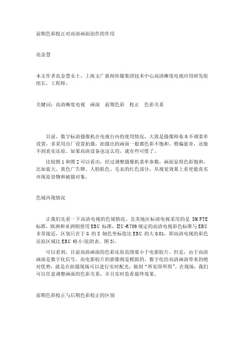
前期色彩校正对高清画面创作的作用
范金慧
本文作者范金慧女士,上海文广新闻传媒集团技术中心高清晰度电视应用研发组 组长,工程师。
关键词:高清晰度电视
画面
前期色彩
校正
色彩关系
目前,数字标清摄像机在电视台内的使用情况,大致是摄像师基本不调菜单 设置,多采用出厂设置拍摄,拍摄出的画面一般都色彩不饱和、稍偏蓝青,还做 不到真实还原。如果高清设备也这么用,就有些可惜了。 比较图 1 和图 2 可以看出,经过调整摄像机菜单参数,画面显得色彩饱和, 比如蓝天、黄色广告牌、人脸肤色、毛衣的红色部分,从视觉效果上看更能真实 再现原景物和被摄对象。
思路:将画面中亮部压暗,同时加上蓝色调以模拟蓝天效果。
(4)调整 Paint 菜单中 BLK Gamma 页中 RGB Level 项的 R、G、B 三通道的电 平比例,遵循三基色原理和加色混合法原理进行调整,可以改变画面中暗部的色 彩关系。 图 16 导演要求画面中其他元素不变, 但是黑色琴键偏蓝紫色, 为了获得这种 效果,作如下调整: PAINT 菜单/BLK GAMMA 页 R +99 G0 B+99 M-99
ofite900 使用步骤
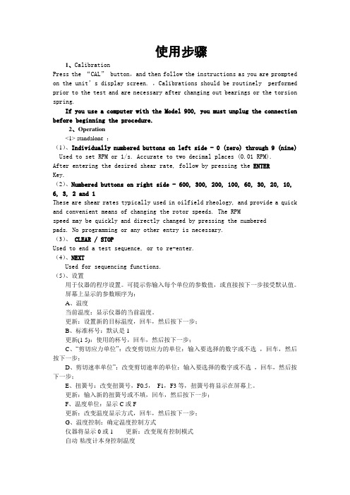
使用步骤1、CalibrationPress the “CAL” button,and then follow the instructions as you are prompted on the unit’s display screen. ,Calibrations should be routinely performed prior to the test and are necessary after changing out bearings or the torsion spring.If you use a computer with the Model 900, you must unplug the connection before beginning the procedure.2、Operation<1> standalone :(1)、Individually numbered buttons on left side - 0 (zero) through 9 (nine) Used to set RPM or 1/s. Accurate to two decimal places (0.01 RPM).After entering the desired shear rate, follow by pressing the ENTERKey.(2)、Numbered buttons on right side - 600, 300, 200, 100, 60, 30, 20, 10, 6, 3, 2 and 1These are shear rates typically used in oilfield rheology, and provide a quick and convenient means of changing the rotor speeds. The RPMspeed may be quickly and directly changed by pressing the numberedpads. No programming or any other entry is necessary.(3)、CLEAR / STOPUsed to end a test sequence, or to re-enter.(4)、NEXTUsed for sequencing functions.(5)、设置用于仪器的程序设置。
- 1、下载文档前请自行甄别文档内容的完整性,平台不提供额外的编辑、内容补充、找答案等附加服务。
- 2、"仅部分预览"的文档,不可在线预览部分如存在完整性等问题,可反馈申请退款(可完整预览的文档不适用该条件!)。
- 3、如文档侵犯您的权益,请联系客服反馈,我们会尽快为您处理(人工客服工作时间:9:00-18:30)。
其它模式12GOT-F900图形操作终端MITSUBISHI12-112.其它模式本章说明其它模式,在其它模式中提供了时间开关、打印机输出和系统设定等方便功能。
12.1其它模式概要◆基本操作a)设置时间开关在指定时间打开指定的位元件。
本功能在使用FX-PCS-DU/WIN-C 时有效。
b)数据传输在画面创建软件和GOT 之间传输用户画面、报警历史和采样数据。
c)打印输出打印采样数据、报警历史等。
d)进入密码登记进入密码保护PLC 中的顺控程序。
e)设置模式允许进行操作GOT 所需要的系统设置,如系统语言和连接的PLC 等。
·在其它模式中提供了如下功能。
模式选择画面第5.3节选择其它模式显示其它模式画面显示如下画面其它模式其它模式12GOT-F900图形操作终端MITSUBISHI 12-212.2设置时间开关用GOT 内置的时钟功能设置时间开关。
本功能可以在达到指定的星期几和时间时在设定的时间闭合多达8个连续的位元件。
目标元件可以用FX-PCS-DU/WIN-E 指定。
(使用GT Designer 时,本功能在SW4D5C-GOTR-PACKE(A)或以后版本中提供。
)其它模式12GOT-F900图形操作终端MITSUBISHI12-3◆基本操作星期几:按星期几选择所需的日子。
选择的星期几下边加了一个“●”。
如果再按一下用“●”标记的星期几,则选择被取消。
开始时间:选择打开指定位元件的时间。
在选择的星期几从开始时间到结束时间元一直保持为O N 。
结束时间:如果结束时间比开始时间早,指定元件在第二天仍然保持为ON(即使没有选择第二天)。
a)目标元件指定多达8个的连续元件。
·在画面2的设置中,(CH1)M100在星期一到星期五的10点11分12秒到10点12分12秒保持为ON。
显示其它模式画面第5.3节到选择通道(=位元件)可以设置1到8个选择“设置时间开关”画面2画面1〈例〉子[其它模式菜单]画面1[ 通道 ]画面2显示通道设置画面选择 SET TIME SWITCH (设置时间开关)移动光标至SETTIME SWITCH(设置时间开关)并按下回车键。
选择频道(=位元件)可在1~8之间选择。
选择工作日START TIME (开始时间)和END TIME (结束时间)选择设置的项目。
可指定工作日,START TIME(开始时间)和END TIME (结束时间)输入时间退出设定按下"-"键进行选择或反选。
[触摸键操作]显示其他模式画面到显示其它模式画面第5.3节[F920GOT-K 中的操作]其它模式12GOT-F900图形操作终端MITSUBISHI12-412.3数据传输可以在GOT 和用于创建画面的外设单元(个人计算机)之间传输(读/写)画面数据、采样数据和报警历史。
◆基本操作·使用下列操作,可以显示数据传输画面。
不管在从个人计算机向GOT 传输数据时显示什么画面都会显示下列画面。
传输完成以后,如果使用FX-PCS-DU/WIN-E 就显示0号画面,如果使用GT Designer 就显示1号画面。
但是,如果用来传输来自个人电脑的画面数据的RS-232C 端口跟PLC 连接时,应该进行如下的操作来显示DATA TRANSFER(数据传输)画面。
■要点1)在采样时向个人计算机传输数据。
在执行采样时从计算机传输和向计算机传输数据时请记住以下几点。
-PC →G OT :当前执行的采样被放弃。
目前为止获得的采样数据被保存下来。
-PC←G OT :采样继续,获得的采样数据被保存下来。
显示其它模式画面第5.3节选择数据传输显示如下画面[数据传输]其它模式12GOT-F900图形操作终端MITSUBISHI12-512.4打印输出可以打印采样数据和报警历史。
因为可以根据各个打印机执行通讯设置,所以可以使用各种各样的配有RS-232C 接口的打印机。
打印机的通讯设置可以在GOT 的设置模式或用画面创建软件进行。
(F920GOT-K 无法连接打印机。
)·将打印机连接到G O T ,然后通电。
·选择要打印输出的数据。
可以打印的采样数据和报警历史。
对于采样数据,可以设置打印范围。
·操纵GOT,在“OTHER MODE(其它模式)”画面选择“PRINT OUT(打印输出)”。
◆基本操作开始打印编号*1 输入的结束打印编号不能比画面上显示的大。
(画面上显示的数字是采样数据的总数。
)连接打印机在GOT 执行选择要打印的数据然后执行打印输出(流程如下所示)打印输出操作打印机输出设置显示如下画面选择采样数据选择报警历史到到结束打印编号 *1打印输出画面取消打印输出开始打印输出显示打印输出画面再次显示如左画面其它模式12GOT-F900图形操作终端MITSUBISHI12-6打印输出的例子·采样数据·报警历史采样元件1采样元件2采样元件3采样元件4其它模式12GOT-F900图形操作终端MITSUBISHI12-712.5进入密码如果在PLC 中登记了进入密码,则禁止在画面模式和监视模式中更改计数器和计数器的设定值,但是可以改变当前值。
(F920GOT-K 只提供解锁功能。
)ENTER(输入)在PLC 中登记一个进入密码。
进入密码和其它外设单元共享。
输入一个8位(FX 系列)或6位(A 系列)十六进制数。
输入进入密码:○○○○○○○○将GOT 电源关闭以后再打开后进入密码生效。
DELETE(删除)删除当前进入密码。
只有在先将进入密码输入单元后才能删除已有的进入密码。
UNLOCK(解锁)暂时解锁已有的进入密码。
(进入密码仍然保持被登记。
)解锁功能在GOT 电源关闭以前一直有效。
备注:如果忘记了已有的进入密码,在一个外设单元中执行“全部清除”。
但要记住全部清除会删除P L C 中的包括程序在内的所有数据。
建议最好不要忘记进入密码。
◆基本操作第5.3节显示其它模式选择进入密码输入进入密码。
画面2到执行登记到执行解锁执行删除输入已有的进入密码。
画面2解锁已有密码。
画面2进入密码画面1画面2到其它模式12GOT-F900图形操作终端MITSUBISHI12-812.6设置模式设置操作GOT 所需的系统设置,如系统语言和连接的PLC 等。
详细的设置内容,参考“5启动”。
◆基本操作第5.3节显示其它模式画面选择设置模式显示设置模式画面。
显示下一页所示的画面。
其它模式12GOT-F900图形操作终端MITSUBISHI 12-9由虚线包围的部分为触摸键。
(实际的画面上并不显示虚线)a )LANGUAGE(语言)允许设置系统画面上使用的语言,如日语或英语。
在“SETUP MODE(设置模式)”的“LANGUAGE (语言)”菜单中的“CHARACTER SET(文字设置)”里设置“WEST EUROPE(西欧)”时,以下9种语言可以被显示:意大利语,英语,荷兰语,瑞典语,西班牙语,丹麦语,德语,葡萄牙语和法语。
系统语言被设置为英语。
(为了显示任意一种上述语言,用在Win dow s操作系统中打开的与相应的语言兼容的画面创建软件来创建画面。
)在如下版本中显示9种语言:F930GOT2.10及以后版本,F940GOT 4.00及以后版本,F943GOT 4.00及以后版本或F940WGOT 中的所有版本。
b )PLC T Y PE(PLC 类型)允许设置连接的PLC 类型c )SERIAL PORT(串口)GOT 上连接了一个打印机或通讯是在GOT 和微型计算机板之间进行时选择。
d )OPENING SCREEN(开机屏幕)允许设置紧接电源打开以后开机画面显示的时间e)MAIN MENU CALL KE Y (主菜单调用键)允许设置从USER SCREEN MODE(用户屏幕模式)里调用SELECT MODE(选择模式)画面的触摸键的位置。
f )SET CLOCK(设置时钟)允许设置用作时间开关和时间显示的参考时间。
g)SET B ACKLIGHT(设置背光)允许设置背光在连续空闲一段时间以后自动关闭的时间。
h )B U ZZ ER(蜂鸣器)允许设置按键时是否发出蜂鸣声。
i)LCD CONSTRAST(F940WGOT:亮度)允许设置LCD 对比度。
m )其它模式12GOT-F900图形操作终端MITSUBISHI 12-10j )CLEAR USER DATA(清除用户数据)删除所有用户画面数据。
k )手持式GOT 设置允许手柄开关或LED(液晶)显示设置(仅用于手持式GOT)l )辅助设置允许向P LC “W R IT E (写入)”或“D O E S N O T WRITE(不写入)”初始显示画面号。
m )END(结束)关闭SET-UP MODE(设置模式)画面,显示SELECT MODE(选择模式)n)光标改变SET-UP MODE(设置模式)画面上的菜单条目。