Additional charged air cooling_TUBerlin
PV Link
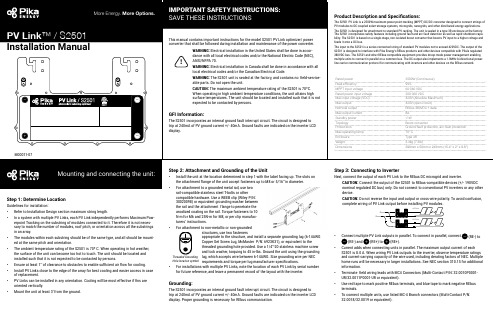
Step 1: Determine LocationGuidelines for installation:• Refer to Installation Design section maximum string length.• In a system with multiple PV Links, each PV Link independently performs Maximum Pow-erpoint Tracking on the substring of modules connected to it. Therefore it is not neces-sary to match the number of modules, roof pitch, or orientation across all the substrings in an array.• The modules within each substring should be of the same type, and all should be mount-ed at the same pitch and orientation.• The ambient temperature rating of the S2501 is 70º C. When operating in hot weather,the surface of the unit can become too hot to touch. The unit should be located and installed such that it is not expected to be contacted by persons.• Ensure at least 1” of clearance to obstacles to enable sufficient air flow for cooling.• Install PV Links close to the edge of the array for best cooling and easier access in caseof replacement.• PV Links can be installed in any orientation. Cooling will be most effective if fins areoriented vertically.• Mount the unit at least 3’ from the ground.rail-compatible stainless steel T-bolts or other compatible hardware. Use a WEEB clip (Wiley P/N: 30020098) or equivalent grounding washer between the rail and the attachment flange to penetrate the anodized coating on the rail. Torque fasteners to 10 N-m for M6 and 25N-m for M8, or per clip manufac-turers’ instructions.• For attachment to non-metallic or non-groundedstructures, use two fastenersappropriate to the structure, and install a separate grounding lug (6-14AWG Copper Set Screw Lug, McMaster P/N: 6923K31), or equivalent to the threaded grounding hole provided. Use a 1/4”-20 stainless machine screw and lock washer, torquing to 45 in-lbs. Ground the unit using the groundinglug, which accepts wire between 6-14AWG. Size grounding wire per NEC requirements and torque per lug manufacturer specifications.• For installations with multiple PV Links, note the location of each PV Link by serial numberfor future reference, and leave a permanent record of the layout with the inverter.Grounding:The S2501 incorporates an internal ground fault interrupt circuit. The circuit is designed to trip at 240mA of PV ground current +/- 40mA. Ground faults are indicated on the inverter LCD display. Proper grounding is necessary for REbus communication.device.CAUTION: Do not reverse the input and output or cross-wire polarity. To avoid confusion, complete wiring of PV Link output before installing PV modules.• Connect multiple PV Link outputs in parallel. To connect in parallel, connect (RE-) to (RE-) and (RE+) to (RE+).•Current adds when connecting units in parallel. The maximum output current of each S2501 is 8.0 A. When wiring PV Link outputs to the inverter, observe temperature ratings and current-carrying capacity of the wire used, including derating factors of NEC. Multiple home runs will be necessary in larger installations. See NEC section 310.15 for additional information.• Terminate field wiring leads with MC4 Connectors (Multi-Contact P/N: 32.0010P0001-UR/32.0011P0001-UR or equivalent).• Use red tape to mark positive REbus terminals, and blue tape to mark negative REbus terminals.•To connect multiple units, use listed MC-4 Branch connectors (Multi-Contact P/N:32.0018/32.0019 or equivalent).Threaded Grounding Hole location symbol REbus380VDC OUTPUTPVSUBSTRIN INPUTWARNING: ELECTRIC SHOCK HAZARD - THE DC CONDUCTORS OF THISPHOTOVOL TAIC SYSTEM ARE UNGROUNDED AND MAY BE ENERGIZED. ELECTRIC SHOCKHAZARD - DC OUTPUT CONDUCTORS MAY BE ENERGIZED REGARDLESS OF SUN EXPOSURE.CAUTION: RISK OF ELECTRIC SHOCK - WHEN THE PHOTOVOL TAIC ARRAY ISEXPOSED TO LIGHT, IT SUPPLIES A DC VOL TAGE TO EQUIPMENT. COVER PV MODULE INOPAQUE MATERIAL BEFORE CONNECTING OR DISCONNECTING THIS OPTIMIZER. DURING FAUL T, ZERO CURRENT IS SOURCED INTO DC ARRAY BY THIS CONVERTER. INSTALL IN。
Ancient_Egyptian“_air_conditioning”_古埃及的“空调”

Crazy English2024.21While the planet continues to endure high temperatures, a 60‑square‑foot shipping container is serving as a testing ground for passive, sustain‑able cooling solutions. An engineering team is uti‑lizing the space to find and improve upon ancientcooling methods that don t generate any forms of greenhouse gas.2 Buildings require roughly 60 percent of the entire world s electricity, almost 20 per‑cent of which is annually used to keep those structures cool and comfortable. As society deals with climate change s most severe effects, air conditioning systems requirements are only expected to rise in the coming years —potentially generating a feedback loop that could worsen carbon emission levels. Finding green ways to lower businesses and homes internal temperatures will therefore need solutions other than simply boosting waste‑ful AC units.3This is especially vital as rising global populations require new construction, particu‑larly within the developing world. According to Omar Al‑Hassawi, lead author and assistant professor in WSU s school of design and construction, this push will be a major issue ifAncient Egyptian “air conditioning ”古埃及的“空调”河北 胡金莹主题语境:科学研究 篇幅:370词 建议用时:7分钟44疯狂英语 (新读写)designers continue to rely on mechanical systems —such as traditional, electric AC units. There s going to be a lot more air conditioning that s needed, especially with the population rise in the hotter regions of the world.4By improving their shipping container test chamber with off‑the‑grid, solar‑powered battery storage, the team can heat their chamber upwards of 130 degrees Fahrenheit to test out their solutions while measuring factors such as temperature and humidity. The team par‑ticularly focused on using a passive cooling method involving large towers and evaporative cooling that dates as far back as 2500 BCE in ancient Egypt. In these designs, moisture evaporates at the tower s top, which turns into cool, heavier air that then sinks down to the habitable space below.5 “It s an older technology, but there s been an attempt to innovate and use a mix of new and existing technologies to improve performance and the cooling capacity of these sys‑tems,” explained Al‑Hassawi, who also envisions changing smokestacks in older buildings to work as new cooling towers.6 Research like this would really help. How can we address building design, revive some of these more ancient strategies, and include them in contemporary building construc‑tion? The test chamber becomes a platform to do this.Reading CheckDetail Detail 1. What s the main advantage of the ancient cooling methods?A. It can save much electricity.B. It doesn t produce greenhouse gas.C. It can ensure the building to be comfortable.D. It can help to innovate buildings structures.2. What effect can air conditioning systems bring?A. They can increase carbon emission levels.B. They can cause serious wasteful behaviour.C. They can bring great challenges to new constructions.D. They can affect people s life in the changing world.45Crazy English2024.2Gist Inference 3. What does paragraph 3 mainly talk about?A. The rise of the world population.B. The working procedure of AC units.C. The major issue in the current world.D. The necessity of innovating cooling solutions.4. What s the author s attitude towards the ancient cooling methods?A. Hopeful. B. Resistant.C. Ambiguous. D. nguageStudyⅠ. Difficult sentence in the textAs society deals with climate change s most severe effects, air conditioning systems requirements are only expected to rise in the coming years —potentially generating a feed‑back loop that could worsen carbon emission levels. 在社会应对气候变化(带来的)最严重的影响的过程中,空调系统的需求预计在未来几年只会上升——这可能会产生一个反馈回路,使碳排放水平进一步提高。
空气延时头的英文

空气延时头英文空气延时头是一种用于调节空气流动的设备,通常用于控制气流的速度和方向。
在英文中,空气延时头的英文表达方式是“air delay head”。
Air delay head is a device used to regulate the flow of air. It is often used to control the speed and direction of airflow. The air delay head can be used in various applications, such as air conditioning systems, ventilation systems, and other systems that require precise control of airflow.In air conditioning systems, the air delay head can be used to control the airflow in individual rooms or areas. By adjusting the settings on the air delay head, it can be adjusted to provide the desired amount of airflow and temperature control. This helps to maintain a comfortable environment and improve the efficiency of the air conditioning system.In ventilation systems, the air delay head can be used to control the airflow in a building or other enclosed space. By adjusting the settings on the air delay head, it can be adjusted to provide the desired amount of fresh air and prevent the buildup of odors or carbon dioxide. This helps to maintain a healthy and comfortable environment for occupants.The air delay head is an important component in many airflow control systems. It provides precise control over the airflow, allowing for optimal performance and comfort in various applications. The air delay head is available in varioussizes and styles to meet the specific needs of different systems and applications.。
厨师Elkay ER21Y远程冷却水冷机产品说明书

PRODUCT SPECIFICATIONSRemote type, electric refrigerated water chiller unit. Chilling Capacity of 2.0 GPH (gallons per hour) of 50︒ F drinking water, based on 80︒ F inlet water and 90︒ F ambient, per ASHRAE 18 testing. Installs directly under fountain or other application, or may be located in a service area to serve a remote outlet (within 15 feet recommended). Unit shall be certified to UL 399 and CAN/CSA C22.2 No. 120.Compact, highly efficient water chiller units are designed for use with any drinking fountain. Also connects to a bubbler, glass filler or cold water dispenser. Converts a fountain into a water cooler.*Based on 80° F inlet water & 90° F ambient air temp for 50° F chilled CONSTRUCTION∙ Cabinet: Rust-resistant galvanized steelCOOLING SYSTEM∙ Compressor: Hermetically-sealed, reciprocating type, single phase. Sealed-in lifetime lubrication.∙ Condenser: Fan cooled, copper tube with aluminum fins. Fan motor is permanently lubricated.∙ Cooling Unit: Combination tube-tank type. Continuous copper tubing is fully insulated with foam that meets UL requirements for self-extinguishing material.∙ Refrigerant Control: Refrigerant R-134a is controlled by accurately calibrated capillary tube.∙ Temperature Control: Easily accessible enclosed adjustable thermostat is factory preset. Requires no adjustment other than for altitude requirements.A Century of Tradition and Quality.For more than 100 years, Elkay has been making innovativeproducts and providing exceptional customer care. We take pride in offering plumbing products that make life easier, inspire change and leave the world a better place.Included with Product: Water ChillerPRODUCT COMPLIANCEBuy American ActCAN/CSA C22.2 No. 120NSF/ANSI 61 (Q≤1) & 372 (lead free) UL 399Installation Instructions (PDF) - 2000000700 Warranty (PDF)PART:________________________________QTY: _____________ PROJECT:______________________________________________ CONTACT:______________________________________________ DATE:__________________________________________________ NOTES:_________________________________________________APPROVAL:_____________________________________________Optional Accessories。
LG EXPRESS COOL 产品说明书

REFRIGERATOROWNER’S MANUALPlease read this manual carefully and throughly before operating this unit.FRIGORÍFICOPor favor leia este manual cuidadosamente e até ao fim antes de operar esta unidadeMANUAL DO UTILIZADOREXPRESS COOLP/No. : MFL41940803Installation1. INSTRUCTIONUnpack the refrigerator and locate at desired location.Refrigerator should be located properly in ventilated area.2. LEVELLINGLevelling of refrigerator should be done with front leg. Refrigerator should be levelled with front to back inclination for base.Note : Push the Defrost Knob after every 2days / Ice Level reaches defrost indicator.Refrigerator Temperature ControlSpecially designed knob gives your facility to control temperature inside Refrigerator.DefrostingIt is natural for moisture in the air to condense on the cold surface. This leads to a regular build up of frost on the surface of the freezer and the cooling in the fresh food compartment. This frost accumulation reduces the cooling effect, thereby reducing efficiency. Therefore, periodic defrosting is necessary to ensure optimum performance.The water in the drain tray evaporates by natural evaporation if defrosting is done once in two days. However, due to varied conditions of usage it is desirable to check the drain-tray occasionally and dispose of the water, if any, Please ensure that the chiller tray is in its correct position by pushing it to its correct position by pushing it to its extreme. Otherwise the defrosting water may fall over the contents of the refrigerator.Manual Defrosting : However in some models, in case of defrosting or power failure the water directly accumulates in chiller tray, dispose off water directly from chiller tray by taking it out.ICE MAKINGFill ice trays with water, place in Freeze Box.To remove ice cube, gently twise Ice Tray.OperationSUGGESTIONSCover or wrap all foods that you put into your refrigerator with polythene or aluminium foil, preventing the mixing of flavours and to keep the food from drying. Do not store liquids in bottles in the freezer compartment since there is danger of their bursting.l Don’t keep hot milk or hot food in your refrigerator. This will result in an increased temperature of other food inthe fridge and may lead to deterioration.l Don’t open the refrigerator door too often-hot air will enter and increase the temperature.l Don’t keep the door open for more than 30 seconds at a time-cold air will rush out of the fridge.l Don’tcover the shelves with paper or plastic sheets. This prevents air circulation inside the cabinet.l Don’t usea knife or sharp instrument to remove the ice trays from the freezer or to remove the frostmechanically as it may damage the freezer coil.l Fridge will automatically switched off when the proper temperature is attained. Don’t switch off the fridge atnight, this will create higher temperature inside the cabinet thus deteriorating stored foods.l Feel free to call your LG Dealer or LG Representative in case your refrigerator has suffered and damage intransit. The Dealer or the Company Representative will assess the extent of damage and give you anestimate for repairs.l Don’t switchon the refrigerator, unless a minimum period of four minutes lapses after it was switched off,either due to power failure or otherwise.l Don’t allow food stuffs smeared with salt to come in direct contact with the freezer. It is a good practice toalways keep the food in a container before placing in the freezer.l Do not keep very hot objects on the table top since the plastic material may get damaged.l Do Not Modify or Extend the power cord length * It will cause electric Shock or fire.SUGGESTIONSIDENTIFICATION OF PARTSDue to continuous product improvement, model specification subjected to change.Check for yourselfType of ComplaintProbable CauseRemedy1.Refrigerator does –Thermostat switch Check that the thermostat knob is on‘Normal' (No.4) position and not in off position.not work. in 'OFF' position.– Power Supply Off.Check that the refrigerator main supply plug is connected to the wall socket and that the supply is on. Check that the fuse is intact in the supply line.2.Refrigerator– Low Voltage.Install a line-correcting transformer in the mains, or a Voltage Stabilizer.attempts to start, but does not operate.3.Refrigerator contents – Defrosting over due Defrost the refrigerator.not cooling.– Restriction of cold Provide space in between the dishes. If the shelves are covered with cloth or air circulation.polythene, remove it.– Improper thermostat If the refrigerator is required to give a low temperature turn the thermostat knob control selection.towards colder (No.7) position.– Entry of hot air.Opening and closing of the door too often will result in hot air from outside rushing into the refrigerator causing the temperature to go up. Reduce the frequency of opening of the door– Storing hot foods.Avoid storing hot foods in the refrigerator, cool them to room temperature before placing them inside the refrigerator.4.Formation of water – High humidity during During the mansoon, when the humidity in the atmosphere reaches around 90%drops on exterior mansoon season.water droplets may form around the sides of the refrigerator cabinet, especially the of refrigerator.top portion. This moisture should be wiped off periodically. Contact our serviceman to check the door seal for proper and uniform contact with the cabinet.5.Formation of droplets – Hot and humid In hot and humid weather the moist air rushes inside whenever the refrigerator dooron the underside of the climate.is opened. This results in excess frosting on the Evaporator, and condensation on Chiller tray.the Chiller tray bottom. Avoid too frequent door openings.6.Smell and odour.– Improper covering Wrap and cover foodstuffs properly. Place caps on bottles and other liquid stores. and wrapping of food.If the smell persists, defrost the refrigerator, remove all foodstuffs, clean the refrigerator thoroughly and wipe it dry before restarting.7.Difficulty in formation – Incorrect thermostat Set the thermostat on 'Colder' (No.7) position.of ice and ice-cream.setting.– Defrosting overdue.Excessive frost on the freezer, should be defrosted. Ensure that the container of ice-cream or ice is in proper contact with the surface of the freezer. Do not use bowls.Before Calling for ServiceEXTERIOR -Use a lukewarm solution of mild soap or detergent to clean the durable finish of your refrigerator. Wipe with a clean, damp cloth and then dry.INTERIOR - Regular cleaning of the interior and interior parts is recommended. If you have the Wash all compartments with a mild baking soda solution, then rinse and dry the compartment.VACATION TIME - During average length vacations, you will probably find it best to leave the refrigerator in operation. Place freezable items in freezer for longer life. When you plan to be away for an extended period remove all food, disconnect the power cord, clean the interior throughly and leave each door OPEN to prevent odour formation.POWER FAILURE - Most power failures are corrected in an hour or two and will not affect your refrigerator temperatures. However, you should minimize the number of door openings while the power is off. During power failures of longer duration, place a block of dry ice on top of your frozen packages.IF YOU MOVE - Remove or securely fasten down all loose items inside the refrigerator. To avoid damaging the leveling screws, turn them all the way into the base.H CELL FRESH CRISPERIt keeps your vegetables fresh by holding moisture & preventsfrom rotten.FeaturesWater dropsUSEFUL SUGGESTIONS。
阿特拉斯GA132-160vsd产品样本
GA 90+-160+ / GA 132-160 VSD90-160 kW / 125-200 hpAtlas CopcoOil-injected Rotary Screw CompressorsWe are committed to your superior productivity through interaction and innovation.Total capability,total responsibilityRight at the heart of your business, Atlas Copco delivers quality compressed air for superior operational capacity. From compressed air generation to point of use, you can choose from our wide range of products to create a complete compressed air system tailored to your specific needs. All Atlas Copco products are engineered to integrate seamlessly, ensuring the highest level of reliability and energy efficiency. As a result, Atlas Copco can take full responsibility for your compressed air infrastructure with a guarantee of best-in-class quality. With a global presence in over 150 countries, we can provide an unrivalled service to maintain and continually improve your compressed air system performance.Backed by 100 years at the forefront of compressed air, Atlas Copco products offer the finest quality and efficiency. Our goal is to be First in Mind—First in Choice ®. That is why Atlas Copco’s pursuit of innovation never ceases, driven by the dedication to meet and exceed your demands. Always working with you, we are committed to providing the customized air solution that is the driving force behind your business.First in Mind—First in Choice 中国空压机在线论坛http://bbs.air-comp.cn/Powerful efficiencyDRIVING DOWN ENERGY COSTSThe cost of compressed air can represent over 40% of your total electrical costs. The GA compressor range achieves a new standard in energy efficiency, helping you spend less. With the addition of VSD (Variable Speed Drive) you can reduce costs by an additional average of 35%. By tuning compressor capacity to fluctuating air demand we can also reduce overall compressor lifecycle costs (LCC) by an average of 22%. The impact on the environment is considerable, reflecting Atlas Copco’s commitment to a safe, healthy world for future generations.BUILT TO LASTEvery GA is designed, manufactured and tested to comply with ISO 9001, ISO 14001 and ISO 1217 stipulations. It uses the latest generation of Atlas Copco’s patented oil-injected screw element, ensuring a long and trouble-free life at the lowest possible operating cost. Engineered for reliable service, even in ambient temperatures up to 55°C/131°F and very harsh environmental circumstances, the GA takes reliability to a new level.PROTECTING YOUR PRODUCTIONClean dry air expands the lifetime of your equipment and protects your investment. The new built-in refrigerant dryer ensures a lower dew point, which is reflected in higher efficiency.FOLLOW-UPTailored service contracts and state-of-the-art add-ons make sure you get the right maintenance, immediate response and genuine spare parts – anywhere in the world.TAILORINGAt Atlas Copco we offer the industry’s broadest portfolio of offerings to help you achieve the most efficient compressed air system for your needs, and optimize your production process at the same time.CHOICEAtlas Copco masters every principle of your air system and offers the most energy-efficient solution for each application.EASY INSTALLATION AND MAINTENANCEGA compressors are delivered ready to use and designed for trouble-free maintenance. The oil and air filters are easily accessible and cooler cleaning procedures are simple. The GA Full Feature (FF) compressor range with its integrated air treatment equipment reduces your installation costs even further, and leaves you the space you need for your application to run.TOTAL CONTROLFrom the Elektronikon ® compressor controller to the ES compressor room controller, Atlas Copco uses the most advanced algorithms designed to reduce your energy costs and ensure your peace of mind by keeping reliability at the maximum level.Efficient, reliable and built to last, the GA 90+-160+ / GA 132-160 VSD compressors are designed to provide high quality compressed air even under harsh conditions. Thanks to Atlas Copco’s Beyond a superior screw elementDRIVING DOWN ENERGY COSTS• The GA Series’ superior screw elements are designed to give the optimum combination of maximum free air delivery for low energy consumption.• The state-of-the-art compressor element is powered by Efficiency 1 class / NEMA EPAct electric motors, contributing to maximum compressor package efficiency.• GA VSD (Variable Speed Drive) compressors automatically adjust the compressed air supply to the demand. Thus the considerable waste of energy caused by no load operation and oil vessel blow-off losses can be avoided.• The VSD-driven radial cooling fans deliver optimum cooling flow and reduced energy consumption in any conditions, through precise fan speed regulation.• The optional Energy Recovery system can recover up to 94% of the compressor shaft power as hot water.• GA 90+-160+ / GA 132-160 VSD compressors feature no-loss drains, which eliminate the waste of compressed air that conventional drains create.• The integrated compressed air treatment includes a refrigerant dryer with the built-in Atlas Copco Patented Saver Cycle Control mode that reduces energy consumption in light load conditions.PROTECTING YOUR PRODUCTION• The aftercooler with integrated water separator immediately removes 100% of the condensate, delivering a higher quality of air than conventional external separators with typically low efficiencies (40-90%). This protects the downstream equipment from corrosion and water damage.• Thanks to Elektronikon-controlled drains, there is no risk of condensate building up and no risk of water suspended in the compressed air.• The GA’s integrated compressed air treatment (refrigerant dryer and compressed air filter) increases the quality of your end product by removing moisture, aerosols and dirt particles.BUILT TO LAST• The GA series’ superior screw element’s patented asymmetric rotor profile and meticulous bearing selection ensure low wear and tear and increased reliability.• All compressors feature TEFC IP55 motors designed for continuous operation under severe ambient temperature conditions up to 55°C / 131°F*.• The heavy duty air inlet filter works with a 2-step dust separation system, which protects the compressor components from wear, even in the dustiest environments.• The GA VSD (Variable Speed Drive) motors have been designed specifically to operate ideally during flexible air demands. The special motor design includes protection against bearing currents and optimizes motor cooling at lower speeds.• The GA VSD frequency converters feature epoxy coated electronic cards, and a heavy duty cooling air filtration is available as an option for operation under the dustiest environments.* Standard up to 46°C / 115°F. (Optional up to 55°C / 131°F)long-standing experience and pioneering innovations there’s a GA compressor available to cut costs and enable smooth, continuous operation right across your production processes.LOW MAINTENANCE COSTS• The heavy duty air inlet filter features a pre-separation cyclone which reduces the dust load in the fine filter doubling the filter element lifetime without reducing filter efficiency.• The high efficiency air/oil separation system consists of a 2-step separation system providing low residual oil content in the compressed air. Low oil consumption ensures low maintenance costs and longer up time.• The VSD radial cooling fans are maintenance-free with bearings greased for life.• Condensate is constantly removed from the water drains.A large diameter drain port removes the potential for clogging, providing trouble-free operation and minimal maintenance.• Replacement of the heavy duty oil filter is simple and quick.• For extended service intervals 8,000-hour oil filters are included as standard.• A mobile phone messaging option facilitates easy planning of routine maintenance activities. Efficient maintenance practices reduce the maintenance costs and ensure optimal compressor performance.ENVIRONMENTALL Y RESPONSIBLE• The VSD radial cooling fans and strong sound insulation reduce noise emissions to less than 71 db (A).• The Variable Speed Drive automation and instrumentation comply with 89/336/EEC directives and operate without any risk of electromagnetic interference.• VSD reduces electricity consumption by an average of 35%, enabling companies to become more independent of electricity supplies and reducing harmful CO2emissions.• The Energy Recovery system recycles energy back into hot water and air which can be used elsewhere in the production environment.LOWERED INSTALLATION COSTS• Totally assembled compressor package. No need to assemble loose shipped components. Simply connect a power supply, compressed air piping, and cooling water piping (for the water cooled version) and the compressor is ready to work.• The Full Feature concept comprises the total compressed air system compressor and air treatment equipment. It is all integrated inside the compressor canopy, limiting both installation costs and space requirements.A state-of-the-art integrated solution• The unique and patented Saver Cycle Control stops the dryer when the compressor is stopped or in unload mode, drastically reducing the power consumption. T he dew point is continuously monitored and the dryer is started again when the dew point starts to increase.• By adjusting the speed of the refrigerant compressor, the integrated VSD dryer control* provides maximum energy saving in low load conditions.• The dryers can perform at ambient conditions of up to 46°C / 115°F . High ambient temperature version available for temperatures up to 50ºC as an option.• Compressor and dryer are designed to work optimally together to perform smoothly under the most critical conditions.* GA VSD Full Feature onlyFEATURES OF THE ExTREME DUTY INTEGRATED REFRIGERANT DRYERINCREASE YOUR PRODUCTION RELIABILITYLow quality air heightens the risk of corrosion in your system, which can lower the life span of your air tools and production equipment. The GA’s filtration process produces clean air that enhances your system’s reliability, avoiding costly downtime and production delays.PROTECT THE ENVIRONMENTWith leaks and energy waste minimized and the unsafe disposal of untreated condensate eliminated, you can safeguard the environment and comply with stringent international regulations.INTEGRATED PURITYThe filters and integrated refrigerant-type air dryer (IFD) efficiently remove moisture, aerosols and dirt particles to protect your investment. This quality air expands the life of equipment, increasing efficiency and ensuring quality in your final product.SAFEGUARD YOUR PRODUCT QUALITYCompressed air coming into contact with your final products should not affect their quality. T he GA provides the clean, dry air that will protect your product’s reputation in the marketplace.DRIVING DOWN ENERGY COSTSClean, treated air reduces the risk of corrosion and leaks in your compressed air system. A 3 mm leak could easily add up to €1800 to your energy bill annually.Protecting your productionUntreated compressed air contains moisture, aerosols and dirt particles that can damage your air system and contaminate your end product. Resulting maintenance costs can far exceed air treatment costs. We believe in effective prevention.14 BAR 7 BARTotal control, assured efficiencyThe Elektronikon ® operating system provides monitoring to increase your compressor’s efficiency Easily expandable with extra sensors, digital inputs and internet communication functions, the Elektronikon can to your specific needs – offering simple, central and control of up to four compressors. For optimal ease of use, FULL Y OPTIMIZED SYSTEMThe ES Multiple compressors• Eliminating the inefficient transition period from full to no load power.• Avoiding excessive off load power consumption.• Maintaining the net pressure band within 0.10 bar, 1.5 psi.• Reducing overall average working pressure.• Minimizing system leakage due to a lower system pressure.• Increasing flexibility with soft starting gradual motor ramp-up to avoid electricity surges.• Offering flexible pressure selection from 3,5 to 14 bar with electronic gearing to ensure lowered electricity costs.With VSD (Variable Speed Drive) technology, air supply mirrors air usage – automatically adjusting the motor speed depending on demand. Lowered system pressure minimizes energyuse across all production processes to reduce energy costs. With VSD technology, Atlas Copco has made major energy savings a reality.VSD: Adapt to the flow, control your costsUsing innovative analysis technology, Atlas Copco engineers can map the fluctuations in demand in your current compressed air system and simulate the energy savings a VSD compressorcould bring to your production process. Ask your Atlas Copco representative for more information.THE GA VSD REDUCES ENERGY COSTS BY:JUST HOW MUCH CAN YOU SAVE?Driving down energy costsBecause there is no unnecessary power generated, the GA reduce energy costs by more. Lifecycle costs (LCC) of the compressor can be reduced by an average of 22%. In general, extra cost of a VSD compressor compared to a fixed speed one can be earned back after just one to two Traditional compressors with a full load, no control operate between set pressure points. maximum pressure is the compressor goes off During periods of medium to low air demand, the no load thE high PricE of fLUctUating DEmanDAir DemAnDenerGY CoSTStandard costsair Demand TimeVSD costsAir DemAnDTimeenerGY CoSTair Demand VSD: VariabLE VoLUmE, controLLED coStSLcc of a StanDarD comPrESSorinstallationmaintenance investment Energy consumption VSD comPrESSorinstallationmaintenance investment Energy consumption average 35% Energy Savings1234The Elektronikon ® system controls both the compressor and theintegrated converter; thus ensuring maximum machine safety as well as easy networking of the compressor.All Atlas Copco VSD compressors are EMC tested and certified.External sources do not influence the compressor operation, nor does the compressor affect the operation of other instruments via emissions or via the power supply line.Mechanical enhancements ensure that all the components operatebelow critical vibration levels within the complete compressor speed range.The frequency converter, low consumption, cooling fan ensuresstable operation even in high ambient temperatures up to 50°C / 122°F*INTEGRA TED VSD – THE SMART CHOICE• The machine is tested for the complete speed range to eliminate any ‘speed windows’ that could jeopardize the energy savings and the stable net pressure. (Turndown capability of the compressor is maximized to 80-85%.)• Special attention is given to the electric motor, which is specifically designed for VSD operation (inverter duty motor). Bearings are protected against induced bearing currents and both motor and converter are perfectly tuned to obtain the highest possible efficiency over the entire speed range.*Standard up to 46°C/114.8°F , optional high ambient version up to 50°C/122°F .SecondsmaximumFlowoperating rangemotor speedCombined motor/converter efficiency100 %1234WHAT ENERGY?Air compression creates heat that is normally wasted in the coolers. Atlas Copco-designed energy recovery systems enable the recovery of most of this heat. Recovery of energy from the shaft input of the compressor can be up to 94% of the compressor shaft power.WHY RECOVER ENERGY?Energy costs can constitute 80% of the total costs of compressed air production. With rising energy prices, saving energy also means a substantial cost saving .With global warming, Kyoto directives and the gradual depletion of traditional energy sources, every business has a duty to contribute as much as possible to overall energy conservation .HOW IS THE ENERGY RECOVERED?Energy recovery systems are integrated modules that recover heat which is otherwise wasted. The heat in the form of hot water (85-90 °C) is directly usable as a source of energy. The main module of the recovery system is built into the compressor.Shaft power100 %Radiant losses2 %Remaining heat in compressed airJul 04 Oct 04 Jan 05 Apr 05 Jul 05 Oct 05 Jan 06 Apr 06 Jul 06Date0.750.70.650.60.550.50.450.40.350.3P r i c e /l i t e r (€)evolution of the fuel oil prices (example from a european country)Maximize your savings…process water boilerHOW CAN THE RECOVERED ENERGY BE USED?The hot water generated can be put to several uses in the industry:• as preheated boiler feed water for industrial processes • for space heating by circulation in radiators or for showers • for other industrial applications like dyeing textiles, operation of absorption chillers, etc.The hot water produced should be used as an auxiliary source of energy, as the load of the compressor and thus the amount of heat produced may vary.HOW DO I BENEFIT?You save energy wherever energy as an auxiliary source to reduce your operating costs.The investment needed to link the hot oil circuit from the compressor to the existing water circuit is relatively modest and the time needed from your investment is generally very short.ASSUMPTIONS• example chosen is a 160 kW GA compressor• 8,000 running hours/year at full load and full energy recovery• cost of fuel oil: €0.55/l• figures shown are an example. Price calculations can Investment in energy recovery system is recovered in less than 2 months Compressor is paid back in less than 2 years Net gain of €570,000 in 10 years**Calculation only includes energy costs as maintenance will remain approximately the same as for a standard compressor.1570,00090,00060,00030,000S a v i n g s (€)Lifecycle costcentral heatingshowers…recover energyAt Atlas Copco, our responsibility doesn’t stop when the product is delivered. An extensive portfolio of exclusive Aftermarket products and services is designed to add maximum value for our customers – no hidden costs, no surprises and minimized risk to your processes. Guaranteed serviceability within 24 hours ensures optimum availability and reliability of your compressed air systems with the lowest possible operating costs. We deliver this complete service guarantee through our extensive Aftermarket organization, maintaining our position as the leader in compressed air.Peace of mindACTIVITY PRODUCT*Genuine parts Atlas Copco Service kits & oils Extended warranties AIRXtendService contracts ServicePlanSystem audits AIR Scan™Remote monitoring AIR Connect™Energy saving AIR Optimizer™Product improvements Upgrade programs* more information is available from your local atlas copco customer center.Complete scope suiting all needsIncluded as StandardHeavy duty Air inlet filter TEFC IP55 Class F electric motorAir intake flexible StartersAir intake valve (not on VSD units)Pre mounted electrical and VSD cubiclesCompressed air aftercooler and oil cooler Flexible vibration dumpersVSD cooling fans for air cooled units Air / oil separatorIntegrated water separator Elektronikon control systemElectronic water drains with no loss of compressed air Full load / no load regulation system (not for VSD)Heavy duty oil filters Silencing canopyComplete air, oil, water circuit Supression of emissions / harmonic distortionsOil containing structural skid with no need for foundations Stainless steel tube and Shell coolers for water cooled unitsAvailable options / Model GA 90+ - 160+GA 110 - 160GA 132 - 160 VSD Full Feature: integrated ID refrigerant dryer x x x Integrated DD pre-filter (only with integrated dryer)x x x Integrated energy recovery system x x x Separate air intake x x x Modulation Control x x N.A.High Ambient Version (up to 55 ºC / 131 ºF * )x x x Phase sequence relay x x standard** PT1000 T hermal protection in the main motor windings and bearings x x standard** Oversized main motor x N.A.N.A.Anti-condensation Heater in the main motor x x N.A.VSD cabinet heavy duty filtration (Applicable for VSDs)N.A.N.A.xNema 4 Cubicle x x N.A.Roto-Xtend Duty fluid 8000h x x xNPT connections x x x Anchor Pads x x x Performance test certificate x x x Witnessed performance test x x x Material Certificates x x x Seaworthy packaging x x xRain Protection Kit x x N.A.IT / NT network system x x xSPM vibration monitoring system x x xGSM alarm messaging system x x x Automatic water shut-off valve for water cooler units x x x Thermostatic water regulating valve N.A.N.A.x* GA Full feature 50 ºC / 122 ºF; GA VSD 50 ºC / 122 ºF; GA fix speed Pack 55 ºC / 131 ºF** Functionalities integrated in the frequency converter protectionsDimensionsCompressor typeAircooled Pack Aircooled Full Feature Watercooled Pack & Full Feature L W H L W H L W H mm inch mm inch mm inch mm inch mm inch mm inch mm inch mm inch mm inchGA 90+-160+260010220007920007932001262000792000792600102163064200079 GA 110-160260010220007920007932001262000792000792600102163264200079 GA 132-160 VSD320012620007920007938001502002792347923200126163064234792(1) Unit Performace Measured according to ISO 1217, Ed. 3, Annex C - 1996 faD is measured at the following working pressures- 5.5 bar variants at 5 bar- 7.5 bar variants at 7 bar(4) maximum working pressure for GA VSD - 8.5; 10;14 bar (e) / GA VSD FF - 8.3; 9.8 ; 13.8 bar(1) Unit Performace Measured according to ISO 1217, Ed. 3, Annex C - 1996 faD is measured at the following working pressures- 75 psi variants at 73 psi- 100 psi variants at 100 psi(4) maximum working pressure for GA VSD - 8.5; 10;14 bar (e) / GA VSD FF - 8.3; 9.8; 13.8 barIn order to be First in Mind—First in Choice ® for all your compressed air needs, Atlas Copco delivers the products and services that help increase your business’ efficiency and profitability.Atlas Copco’s pursuit of innovation never ceases, driven by your need for reliability and efficiency. Always working with you, we are committed to providing you the customized quality air solution that is the driving force behind your business.2935 0548 10 – P r i n t e d i n B e l g i u m – S u b j e c t t o a l t e r a t i o n w i t h o u t p r i o r n o t i c e .Never use compressed air as breathing air without prior purification in accordance with local legislation and standards.。
Futaba SkyLeaf Samba f Electric RC Airplane Instru

Manuals+— User Manuals Simplified.Futaba SkyLeaf Samba f Electric RC Airplane Instruction ManualHome » Futaba » Futaba SkyLeaf Samba f Electric RC Airplane Instruction ManualFutaba SkyLeaf Samba f Electric RC AirplaneInstruction ManualTo maximize your enjoyment, and to ensure proper flying, please read through this assembly instruction manual.Futaba guarantees this kit to be free from defects in both material and workmanship at date of purchase. This warranty does not cover any component parts damaged by use or modification. In no case shall Futaba liability exceed the original cost of the purchased kit. Further, Futaba reserves the right to change or modify this warranty without notice.In that Futaba has no control over the final assembly or material used for final assembly, no liability shall be assumed nor accepted for any damage resulting from the use by the user of the final user-assembled product. By the act of using the user-assembled product, the user accepts all resulting liability. If the buyer is not prepared to accept the liability associated with the product, the buyer is advised to return this kit immediately in new and unused condition to the place of purchase.PrecautionsApplication and Modification Precautions.1. This product is only designed for use with radio control models. Use of the product described in this instructionmanual is limited to radio control models.2. Modification, adjustment, and parts replacement:Futaba is not responsible for unauthorized modification, adjustment, or replacement of parts on this product.3. Your Sky Leaf should not be considered a toy, but rather a sophisticated, working model that functions verymuch like a fullsize airplane. Because of its performance capabilities, this airplane, if not assembled and operated correctly, could possibly cause injury to yourself or spectators and damage to property.4. You must assemble the model according to the instructions. Do not alter or modify the model, as doing so mayresult in an unsafe or unflyable model. In a few cases the instructions may differ slightly from the figures. In those instances the written instructions should be considered as correct.5. You must take time to build straight, true and strong.6. You must use an R/C radio system that is in good condition, a correctly sized motor, and other components asspecified in this instruction manual. All components must be correctly installed so that the model operates correctly on the ground and in the air. You must check the operation of the model and all components before every flight.7. If you are not an experienced pilot or have not flown this type of model before, we recommend that you get theassistance of an experienced pilot in your R/C club for your first flights. If you’re not a member of a club, your local hobby shop has information about clubs in your area whose membership includes experienced pilots. 8. While this kit has been flight tested to exceed normal use, if the plane will be used for extremely high stressflying, such as racing, or if a motor larger then one in the recommended range is used, the modeler isresponsible for taking steps to reinforce the high stress points and/or substituting hardware more suitable for the increased stress.■ No part of this manual may be reproduced in any form without prior permission.■ The contents of this manual are subject to change without prior notice.■ Futaba is not responsible for the use of this product by the customer.■ Company and product names in this manual are trademarks or registered trademarks of the respective companyFor safe usePlease observe the following precautions to ensure safe use of this product at all times.Meaning of Special Markings:The parts of this manual indicated by the following marks require special attention from the standpoint of safety.WARNING: Always keep R/C components away from small children.Assembly PrecautionsStorage and Disposal PrecautionsOther PrecautionsFlying PrecautionsBattery and Charger Handling Precautions1) Required for operation (Purchase separately)2) Set Contents3) Wing Assembly4) Stabilizer Installation5) Motor Cowl Installation6) Main Gear Installation7) Tail Gear Installation8) Receiver & Battery (Not Furnished) Installation9) Wing Installation10) Canopy Installation11) Propeller Spinner12) C.G Position13) Set the Control ThrowsTo ensure a successful flight, fly your skyleaf set up only according to the C.G. in this manual. This providesyou with the best chance for success and enjoyable first flights that should be surprise-free. A model that is not properly setup may be unstable and possibly unflyable.14) SpecificationThe product is not repairable by Futaba service center if damaged.FUTABA Corporation of America2681 Wall Triana Hwy Huntsville, AL 35824, U.S.A.Phone:1-256-461-9399 FAX:1-256-461-1059https:///E-mail: *********************Contents1 Documents /Resources1.1 ReferencesDocuments / ResourcesFutaba SkyLeaf Samba f Electric RC Airplane [pdf] Instruction ManualSamba f, FCA, SkyLeaf Samba f Electric RC Airplane, SkyLeaf Samba f, Electric RC Airplane,RC Airplane, AirplaneReferencesFront Page - FutabaUSA - What's life without a hobby?Manuals+,。
外贸出口货代费用中英文详解

货代费用中英文对照及费用总结空运费-AIR FREIGHT海运费-OCEAN FREIGHT包干费-LOCAL CHARGE电放费-SURRENDED FEE并单费-COMBINED CHARGE改单费-AMEND FEE集卡费-TRUCKING FEE快递费-COURIER FEE熏蒸费-FUMIGATION CHARGE制单费-DOCUMENT FEE注销费-LOGOUT FEE改配费-RE-BOOKING FEE查验费-INSPECTION FEE订舱费-BOOKING FEE保险费-INSURANCE CHARGE外拼费-CO-LOAD FEE内装费-LOADING FEE报关费-CUSTOMS CLEARANCE FEE商检费-COMMODITY CHECKING FEE特殊操作费-SPECIAL HANDLING CHARGE码头操作费-TERMINAL HANDLING CHARGEadvertising cost广告费appraised估价basic price基价buying offer买方发价ceiling price最高价C.I.F. value赶岸价combined offer联合发价cost and freight (C.& F.)到岸价;运费在内价cost and insurance (C.& I.)保险在内价cost, insurance and freight (C.I.F.) 运费及保险在内价counter offer还价:还发价current price现时价entertainment expenses交际费ex-dock (factory)码头(工厂)交货价ex-mine (plantation)矿区(农场)交货价wx-maker’s godown制造商仓库交货价ex-quay (wharf)码头交货价ex-ship输入港船上交货价first cost生产本钱价floor price最低价franco全部费用在内价free alongside(on) ship船边(上)交货价free on rail火车上交货价free overside出入港船上交货价free out (F.O.)卸货费船方免责freight collect运货由提货人交付freight repaid运费预付freight terms岸上交货价landing (loading) charges起货(装载)费local (spot)当地付货价miscellaneous expenses杂项开支net price净价;实价offer on sale or return许可退货发价offer without engagement不受约束发价out-of-pocket expenses零星开支overhead日常开支;日常管理费packing charges包装费prime cost原价;主要本钱rebate回折retail price零售价stevedorage码头工人搬运费storage charges仓租sundry chargesd(expenses)杂费surcharge附加费wharfage码头费wholesale price批发价〔一〕船代Shipping agent 船舶代理Handling Agent 操作代理Booking Agent 订舱代理Cargo Canvassing 揽货FFF: Freight Forwarding Fee 货代佣金Brokerage / Commission 佣金〔二〕订舱Booking 订舱Booking Note 订舱单Booking Number 订舱号Dock Receipt 场站收据M/F (Manifest ) :a manifest that lists only cargo, without freight and charges 舱单Cable/Telex Release 电放A Circular Letter 通告信/通知书PIC: Person in Charge 具体负责操作人员The said party 所涉及的一方On Board B/L: On Board提单 A B/L in which a carrier acknowledges that goods have been placed on board a certain vessel。
- 1、下载文档前请自行甄别文档内容的完整性,平台不提供额外的编辑、内容补充、找答案等附加服务。
- 2、"仅部分预览"的文档,不可在线预览部分如存在完整性等问题,可反馈申请退款(可完整预览的文档不适用该条件!)。
- 3、如文档侵犯您的权益,请联系客服反馈,我们会尽快为您处理(人工客服工作时间:9:00-18:30)。
Heat2Cool-Engine Operation at Charge Air Cooling below Ambient TemperatureDipl.-Ing. Dipl. Vw. Samir Kadunic, Prof. Dr.-Ing. Roland Baar,Dipl.-Ing. Florian SchererFG Verbrennungskraftmaschinen, TU Berlin, GermanyDipl.-Ing. Tobias Zegenhagen, Prof. Dr.-Ing. Felix ZieglerFG Maschinen- und Energieanlagentechnik, TU Berlin, GermanySummaryCharge air cooling below ambient temperature seems promising for increasing spark engine efficiency at high loads. This paper investigates the potential of an exhaust heat driven cooling device employed for low-temperature inter cooling.The effects on engine efficiency are investigated at various points of operation along thermal and mechanical limits of the test engine. Potentials are quantified and turn out to be significant.Detrimental effects on efficiency of low temperature inter cooling at medium and low engine loads are explored. Effects on exhaust emissions during driving cycles are examined. Negative effects at low and medium loads turn out to be negligible.1 IntroductionGiven currently established fuels and standard of technology a significant reduction of CO2emissions can only be achieved by increasing overall vehicle efficiency. A holistic view at the vehicle can focus the attention on the use of waste heat recovery [1, 2, 3, 4]. The use of exhaust heat offers advantages over the use of heat from the engine coolant due to its higher temperature level.On a different note, it can safely be assumed that future legislation will require the fulfillment of emission standards outside of driving cycles [5]. This calls for a different approach to engine operation and calibration at high loads at least for spark ignition (SI) engines.Fig. 1: System setup of the Heat2Cool conceptThis paper reports about experiments employing an exhaust heat driven cooling device (Fig. 1). The system can provide a cold fluid which can be used to cool the charge air below ambient temperature. This concept makes the temperature of the intake charge widely selectable independent of environmental conditions. The basic operability of the combined system of combustion engine and cooling device was proved in [6]. Major milestones for introducing the concept into mass production are control of both systems and vehicle package integration.2 Opportunities from low-temperature intercooling for SI enginesOptimizing efficiency without crossing mechanical and thermal limits is one goal during design and application of turbocharged SI engines. The most relevant limits are turbocharger turbine inlet temperature, maximum cylinder pressure and self-ignition of unburned parts of the cylinder charge (detonation).Fig. 2 visualizes the effective efficiency of the original sample engine in the investigated area of the engine map. Efficiency decreases from its optimum with deviating load and engine speed. Towards low loads throttling increases chargecycle losses and the mechanical efficiency deteriorates.B r a k e m e a n e f f e c t i v e p r e s s u r e i n b a r0510152025Engine speed in min -1Fig. 2: Effective efficiency of the original sample engineAt high loads and engine speeds efficiency is impaired by other limitations. Fig. 3 shows areas where a rich air fuel ratio is required to keep the turbo charger turbine inlet temperature within its limits. In most of these points of operation the centre of heat release has to be later than desired because of limited cylinder pressure capability although there is no knocking. If earlier ignition timing was possible this would relieve the turbocharger turbine thermally.Fig. 3: Areas of critical temperature at turbocharger turbine intake and cylinder pressureAt high loads and low engine speeds, cylinder pressure during combustion is not critical. Nevertheless, ignition timing has to be unfavorably late to prevent knocking in large areas of the engine map (Fig. 4)Fig. 4: Areas of late centre of heat release and rich air fuel ratioThe temperature of the charge air determines the achievable loads before being limited by any of the aforementioned limits of operation. The lower limit of this temperature is set by the coldest medium available for intercooling. Commonly this is the ambient air, but due to limits in heat changer efficiency the charge air will always be several degrees warmer than that temperature.Turbo cooling and Miller cycle can further decrease charge temperature inside the combustion chamber. Both methods require higher supercharging ratios which causes more back pressure if a turbocharger is used. As a single influence this is detrimental for the gas exchange cycle which decreases engine efficiency and increases residual gas content [7].A cooling device provides a fluid colder than ambient temperature. Used for intercooling, this turns the intake charge temperature into a degree of freedom for engine application. It can be used to increase power density or thermal efficiency. As an alternative engine components can be relieved thermally or mechanically.Extensive experimental studies were conducted to determine the potential (Table 1) to guarantee the applicability of the results to future production engines.Previous investigations [8] show no significant influence of super low charge air temperature on efficiency without adapted ignition timing or air-fuel ratio.The application of very cold intercooling combined with high boost ratios results in air moisture condensing inside the intercooler. To prevent icing charge air temperatures below 0°C were avoided. As a reference an intake temperature of 60°C was used to represent high engine loads combined with low vehicle speeds and warm surroundings.Tab. 1: Reference engine specifications3 Experimental resultsIn the following chapters we investigate the potential improvement of SI engine efficiency with intensive inter cooling. Experiments were conducted at the engine’s operating limits and in various significant areas of the engine map.At first we show effects at n=2500min-1 where high load operation is limited by knocking. This demands delayed ignition timing, resulting in high exhaust temperatures, requiring fuel enrichment to cool the turbo charger turbine. With increasing engine speed, peak cylinder pressure leads to late COHR, causing thermal problems with the turbo charger turbine and resulting in rich air-fuel ratios. Effects applicable to these areas of the engine map are demonstrated at n=4500min-1.Sweeps of ignition timing showed the most efficient COHR to be independent of charge intake temperature between 4° and 8° ATDC. The loads achievable within this COHR range are limited by knocking and peak cylinder pressure. In this paper we show the increase in achievable load at a certain COHR by reduced charge air temperature at COHR=4°ATDC and COHR=8°ATDC.Midway of the engine map operation is not restricted by thermodynamic limitations. Effects of inter cooling on engine efficiency are investigated at NMEP=6bar and NMEP=12bar. Low engine loads and speeds are most relevant for driving cycles. The influence of charge air temperature on effective efficiency and emissions areshown for one significant point of operation.turbine inlet temperature and engine knock Charge enrichment is required in some of the areas of the engine map where ignition timing is later than actually desired. In those points of operation the largest improvement in efficiency can be achieved through inter cooling if ignition timing is advanced and the mixture is simultaneously leaned out along the thermal and mechanical limits of the engine.Charge air temperature is decreased in several steps starting from 60°C at n=2500min -1 for two loads (NMEP=18bar; 20bar). Indicated efficiency can be increased by up to 18.5% at constant load (Fig. 5). This is achieved by advancing the ignition timing and leaning the charge mixture accordingly. Turbine intake temperature is reduced by up to 100K additionally.The intake charge temperature and turbine intake temperature correlate stronger at NMEP=18bar than at 20bar. This is attributable mainly to the lower opportunity for leaning the mixture at the lower load. Leaning causes a reduction in laminar flame velocity resulting in longer combustion, diminishing the reduction of exhaust temperature.A charge air temperature reduction of 10K is sufficient for combustion of a stoichiometric mixture at NMEP=18bar. A temperature reduction of 30K is required to achieve the same at NMEP=20bar.Engine load can be increased by 11% to NMEP=22.2bar referencing to an intake temperature of 40°C, employing stoichiometric combustion and assuming constant efficiency.L a m b d aI n d i c a t e d e f f i c i e n c y i n %T u r b i n e i n l e t t e m p e r a t u r e i n °CCharge air temperature after throttle in °CC O H R i n °C A a . TD C FCharge air temperature after throttle in °C M a x . c y l.p r e s s u r e i n b a rN m e p i n b a rFig. 5:Influence of intake air temperature on efficiency and turbine inlettemperature at n=2500min -1employing optimized COHR and Air fuel ratioturbine inlet temperature and mechanical stress Another trial intake temperature was reduced starting at 60°C and investigating two engine loads (NMEP=16 and 20bar) at 4500min -1.At constant load ignition timing could only be advanced moderately due to the given cylinder pressure limit. For this reason most of the efficiency increase originates from the leaner mixture permitted by the decrease in exhaust gas temperature. At NMEP=20bar efficiency can be increased by up to 16% (Fig. 6).If intake air temperature is reduced from 20°C to 0°C at NMEP=16bar the effect on turbine intake temperature becomes clearly visible. A reduction of charge air temperature by 20K results in a thermal relieve for the turbine of 15K.I n d i c a t e d e f f i c i e n c y i n %2426283032343638L a m b d a0.700.750.800.850.900.951.00T u r b i n e i n l e t t e m p e r a t u r e i n °C925938950963975Charge air temperature after throttle in °C7274767880C O H R i n °C A a . TD C F101214161820222426Charge air temperature after throttle in °CFig. 6:Influence of intake charge air temperature on efficiency and turbine intake temperature at n=4500min -1 employing adjusted COHR and air-fuel ratio3.3 Extension knock boundary at part loadSpark ignition engines show best efficiency if the centre of heat release is between 4° and 8°ATDC. At partial load this can commonly be achieved. The maximum load where COHR can be set as aspired is limited by knocking or detonation. For two engine speeds the potential is investigated for an increas engine load while maintaining ideal COHR using intensified inter cooling.At n=2000min -1 engine load can be increased by 37%, see also Fig. 7. Even an increase of 47% is possible at n=3000min -1 and COHR=4° ATDC. In both cases the feasible increase in load is larger for the earlier centre of heat release. An earlier combustion reduces the cross-influence of heat exchange with the cylinder walls on the effects of intensified inter cooling.B r a k e e f f i c i e n c y i n %Charge air temperature after throttle in °C N M E P i n b a rN M E P i n b a rB r a k e e f f i c i e n c y i n %Charge air temperature after throttle in °CFig. 7:Influence of charge air temperature on engine knock limit at n=2000min -1 and n=3000min -1 with COHR at 4°ATDC and 8°ATDC3.4 Influence of charge air temperature on efficiency and emissions at partload A reduction of intake air temperature increases the charge density keeping all other parameters equal. In throttled operation this means intensified inter cooling results in ascending charge cycle losses from throttling for a given load, which may result in decreased overall efficiency. To investigate this situation sweeps in engine speed were run at NMEP=6bar and NMEP=12bar. COHR was kept constant while intake air temperature was varied in steps between 60°C and 0°C (Fig. 8).The selected test engine achieves a full load of approximately NMEP=12bar when naturally aspirated at 60°C intake air temperature. Intensified charge air cooling requires throttling to achieve retention of air mass flow and engine load.The results show no detrimental effect of a lowered charge air temperature on efficiency at the investigated engine loads and speeds. From the measurements it can be derived that a reduction in wall heat losses compensates for the increasing charge cycle losses.I n d i c a t e d e f f i c i e n c y i n %Engine speed in min -1H e a t t r a n s f e r t o c y l i n d e r w a l l i n % o f t o t a l f u e l e n e r g y101214161820222426H e a t t r a n s f e r t o c y l i n d e r w a l l i n % o f t o t a l f u e l e n e r g yI n d i c a t e d e f f i c i e n c y i n %303132333435363738Engine speed in min -1Fig. 8:Influence of charge air temperature on efficiency at NMEP=6 andNMEP=12barDriving cycles like NEDC are dominated by even lower engine loads. From a vehicle simulation 2000min -1 and NMEP=2,8bar was derived as being highly representative. Reducing the charge air temperature is expected to impair mixture formation when keeping all other influences equal. This could result in increasing HC and CO raw emissions. Fig. 9 shows the influence of intake air temperature on effective efficiency and emissions before and after catalytic converter in the aforementioned point of operation. Inter Cooling does not show any significant influence on exhaust emissions nor on efficiency or exhaust gas temperature.Employing cylinder pressure analysis it was found, that integral wall heat loss diminished with decreasing charge air temperature. This results in the cylinder charge temperature being almost independent of intake temperature during the high pressure cycle.B r a k e e f f i c i e n c y i n %N O X i n g /k W hCharge air temperature after throttle in °C H C i n g /k W h02468C O i n g /k W h8152330Charge air temperature after throttle in °C520530540550560Fig. 9: Influence of charge air temperature on brake efficiency and emissions at 2000min-1 and NMEP=2,8bar4 ConclusionThe potential efficiency increase from charge air cooling was investigated at various limits of engine operation employing selected points of operation.Assuming an intake charge air temperature reduction of 60K engine efficiency could be increased by up to 18%. This applies to engine operation at n=2500min-1 NMEP=20bar where operation was limited by knock and turbine inlet temperature. Advanced ignition timing with correspondingly leaned out mixture was employed. If engine operation is limited by peak cylinder pressure and turbine intake temperature, a reduction in charge air temperature by 60K can raise engine efficiency by up to 16%. This was demonstrated at n=4500min-1, NMEP=20bar. The increase in air-fuel ratio was most influential in this case.Employing intensified charge air cooling, the top load before engine knocking can be increased for a given COHR. At n=3000min -1the highest achievable load while employing a desirable ignition timing could be increased by 47%.It was found out that engine efficiency was not detrimentally affected by low temperature inter cooling at low and medium engine loads. A point of engine operation representative for driving cycles was derived and used for further investigation. Charge air cooling below ambient temperature showed no negative effects on exhaust emissions at this low engine load.5 Definitions, Acronyms, AbbreviationsATDC after top dead centera. afterCOHR Centre of heat releaseTDCF Top dead centre firingNMEP Net mean effective pressure6 References[1] FREYMANN, R.; RINGLER, J.; SEIFERT, M.; TILLMANN, H.Der Turbosteamer der zweiten GenerationMTZ 73, 2012[2] FRIEDRICH, H.; SCHIER, M.; HÄFELE, C.; WEILER, T.Strom aus Abgasen: Fahrzeuggerechte Entwicklung thermoelektrischerGeneratorenATZ 112, 2010[3] DINGEL, O.; SEMPER, T.; AMBROSIUS, V.; SEEBODE, J.Waste heat recovery: What are the alternatives to the thermoelectric generator?Thermoelectrics Goes Automotive IIBerlin, 2013[4] SEHER, D.; LENGENFELDER, T.; Gerhardt, J.; EISENMENGER, N.;HACKNER, M.; KRINN, I.Waste Heat Recovery for Commercial Vehicles with a Rankine Process21st Aachen Colloquium Automobile and Engine Technology 2012Aachen, 2012[5] REULEIN, C.; SCHÜNEMANN, E.; SCHWART, C.; WETZEL, M.Thermodynamik des BMW-DreizylindermotorsMTZ 74, 2013[6] KADUNIC, S.; ZEGENHAGEN, T.; BAAR, R.; ZIEGLER, F.Heat2Cool - Abgaswärmenutzung IIFVV Abschlussbericht, Heft R989, 2013[7] PUCHER, H.; ZINNER, K.Aufladung von VerbrennungsmotorenSpringer ViewegBerlin Heidelberg, 2012[8] KADUNIC, S.; ZEGENHAGEN, T.; SCHERER, F.; BAAR, R.; ZIEGLER, F.Heat2Cool - Abgaswärmenutzung IIFVV Zwischenbericht, Heft R558, 2012。