LS5360-HL中文资料
杰克电子 Roll Ball 360度倾斜传感器说明书
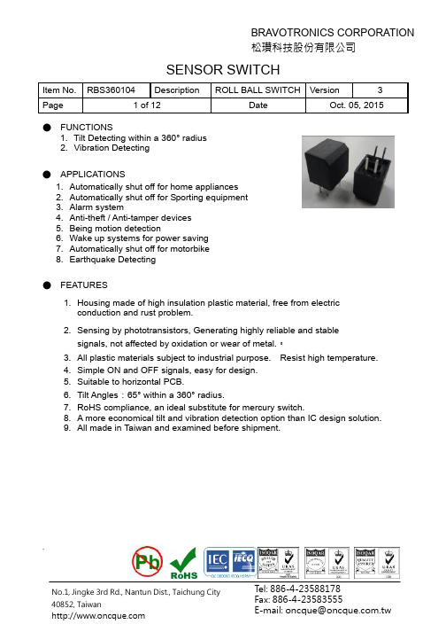
SENSOR SWITCHItem No. RBS360104 Description ROLL BALL SWITCHVersion3Page1 of 12DateOct. 05, 2015.● FUNCTIONS1. Tilt Detecting within a 360° radius2. Vibration Detecting● APPLICATIONS1. Automatically shut off for home appliances2. Automatically shut off for Sporting equipment3. Alarm system4. Anti-theft / Anti-tamper devices5. Being motion detection6. Wake up systems for power saving7. Automatically shut off for motorbike8. EarthquakeDetecting● FEATURES1. Housing made of high insulation plastic material, free from electric conduction and rust problem.2. Sensing by phototransistors, Generating highly reliable and stable signals, not affected by oxidation or wear of metal.。
3. All plastic materials subject to industrial purpose. Resist high temperature.4. Simple ON and OFF signals, easy for design.5. Suitable to horizontal PCB.6. Tilt Angles :65° within a 360° radius.7. RoHS compliance, an ideal substitute for mercury switch.8. A more economical tilt and vibration detection option than IC design solution. 9. All made in Taiwan and examined before shipment.SENSOR SWITCHItem No. RBS360104 Description ROLL BALL SWITCHVersion3Page2 of 12 DateOct. 05, 2015.● PATENTS1. Taiwan Patent No.: M 4200332. Taiwan Patent No.: M4508173. Taiwan Patent No.: I 4514634. China Patent No.: ZL 2011 2 0339658.75. China Patent No.: ZL 2012 2 0539712.76. USA Patent No.: US 8,927,919,B2● DIMENSIONS / OPERATION / P .C.B. LAYOUT (Unit: mm, Tolerance: ±0.25mm)Table 1SENSOR SWITCHItem No. RBS360104 Description ROLL BALL SWITCHVersion3Page3 of 12 DateOct. 05, 2015.● Current/Voltage SuggestedInput Current (mA)Operating Voltage (V)Condition10 3.3 V CE =3.3VR D =200 ohmR L =15K ohm 10 5 V CE =5VR D =390 ohmR L = 22K ohm*Please refer to above Application Circuit for designing electrical circuit.● Absolute Maximum Rating (Ta=25℃)Item Symbol Rating Unit InputPower DissipationPd 75 mWReverse Voltage V R 5 V Forward CurrentI F 50 mA Peak Forward Current (*1) I FP 1 A OutputCollector Power DissipationP C 100 mW Collector Current I C 20 mA C-E Voltage V CEO 30 V E-C VoltageV ECO 5 V Operating Temperature Topr -25 ~ +85 ℃ Storage Temperature Tstg -40 ~ +85 ℃ Soldering Temperature (*2)Tsol260℃(*1) tw=100 μSec.、T =10 mSec.(*2) t=5 SecSENSOR SWITCHItem No. RBS360104 Description ROLL BALL SWITCHVersion3Page4 of 12 DateOct. 05, 2015.● Electrical Optical Characteristics (Ta=25℃)Parameter Symbol Condition Min.Typ. Max. UnitForward Voltage V F I F =20mA - 1.2 1.5 V Reverse Current I RV R =5V--10μAPeak Wavelength λp I F =10mA 940 nm Dark CurrentIceo V CE =10V - - 100μAC-E Saturation Voltage V CE (sat)I C =0.25mAI F =20mA --0.4 VLight Current I C V CE =5V I F =20mA 0.5 5 - mA Rise Time Tr I C =0.8mA V CC =30V R L =1K Ω- 5 - μsec Fall Time Tf-5-μsecSENSOR SWITCHItem No. RBS360104 Description ROLL BALL SWITCHVersion3Page5 of 12DateOct. 05, 2015.● Typical Electrical / Optical Characteristics Curves (Ta=25℃)SENSOR SWITCHItem No. RBS360104 Description ROLL BALL SWITCHVersion3Page6 of 12DateOct. 05, 2015.SENSOR SWITCHItem No. RBS360104 Description ROLL BALL SWITCHVersion3Page7 of 12 DateOct. 05, 2015.● ELECTRICAL CHARACTERISTICS 1. Contact Rating -- 2. Contact Resistance --3.Differential AngleRefer to Table 1 4. Insulation Resistance -- 5. Dielectric Strength -- 6. Capacitance --● RELIABILITY TESTTest Item StandardContentsIR Reflow -- --Operating Temp MIL-STD-202G,TEST METHOD 107G, TEST A -25°C~85°C Storage Temp MIL-STD-202G,TEST METHOD 107G, TEST A -40℃~85℃ Humidity Test MIL-STD-202G,TEST METHOD 103B40℃/95%RH Mechanical Test --2Hz, horizontal 1,000,000 times Operation LifeTest MIL-STD-883E:1016I F =20 mA, V CE =5 V TIME: 30,000 hrsSENSOR SWITCHItem No. RBS360104 Description ROLL BALL SWITCHVersion3Page8 of 12 DateOct. 05, 2015.● SOLDERING CONDITIONFollowing soldering conditions are for reference only, please use soldering information that solder paste manufacturer recommends.SENSOR SWITCHItem No. RBS360104 Description ROLL BALL SWITCHVersion3Page9 of 12 DateOct. 05, 2015.< Table of classification Reflow profile >Item Pb process Pb free processPre-heat and Soak Temperature min.(Tsmin) Temperature max.(Tsmax) Time (Tsmin to Tsmax)(ts) 100 °C 150 °C 60-120 seconds 150 °C 200 °C 60-120 seconds Average ram-up Rate(Tsmax to Tp)3 °C/second max. 3 °C/second max.Liquidous Temperature(TL)Time at Liquidous (tL) 183 °C 60-150 seconds 217 °C60-150 secondsPeak package body Temperature (Tp)*230 °C ~235 °C * 255 °C ~260 °C * Classificationtemperature(Tc)235 °C 260 °CTime(tp)** within 5 °C of the specified classification temperature (Tc)20** seconds 30** seconds Average ram-down Rate(Tp toTsmax)6 °C/second max. 6 °C/second max.Time 25 °C to peaktemperature6 minutes max. 8 minutes max.* Tolerance for peak profile temperature (Tp) is defined as a supplier minimum and a user maximum. ** Tolerance for time at peak profile temperature (tp) is defined as a supplier minimum and a user maximum.SENSOR SWITCHItem No. RBS360104 Description ROLL BALL SWITCHVersion3Page10 of 12 DateOct. 05, 2015.ProfileSENSOR SWITCHItem No. RBS360104 Description ROLL BALL SWITCHVersion3Page11 of 12 DateOct. 05, 2015.● PACKAGE Part Number Package Quantity Total Q’ty Size (mm) 1.RBS360104IC Tube 48 pcs 48 pcs 525L*10W*17.5H Inner box 84 Tubes 4,032 pcs 539L*130W*130H Carton4 Boxes16,128 pcs551L*285W*288H※ Package is shown as below for reference !Inner box CartonIC TubeSENSOR SWITCHItem No. RBS360104 Description ROLL BALL SWITCHVersion3Page12 of 12 DateOct. 05, 2015.● NOTE1. Suggestion for usage :For vibration usage or application ,we suggest to add hysteresis (on delay) for IC.2. For the continued product improvement as one of the company policy,specifications may change or update without notice. The latest information can be obtained through our sales offices. Normally, all products are supplied under our standard conditions.● PRECAUTIONS FOR USE1. If the products is intended to be used for other endurance equipment requiringhigher safety and reliability such as life support system, space and aviation devices, disaster and safety system, it’s necessary to make verification of conformity or contact us for the details before using.2. Do not clean the switch with solvent or similar substance after the solderingprocess.3. Use water-soluble flux may damage the switch.4. When the soldering temperature exceeds specifications, the switch may fall apart.5. Do not use switch in the environment of high humidity ,because such anenvironment may cause the leakage current between the terminals.6. More than the rated load may cause fire, so do not use more than the load7. In the circuit ,switch should not be near or directly connected with the magneticcomponent solder joints (for example: relays, transformers, etc.).8. To prevent damaging IR and PT, please make ESD protection, for example:wearing a conductive wrist strap or antistatic gloves during production process, or grounding machinery etc.。
英斯特朗电子万能材料试验机
安全
关系到安全的关键功能由控制器直接实现,而不是通过计算机 软件间接实现。这样能对紧急情况和限位开关做出最快的反应, 一旦有这些情况发生,控制器会检测到试验过程中传感器断开, 停下横梁。如果计算机关机或者软件出现错误,机器会自动切 换到等待模式。力传感器达到满载荷的 105% 时会有自动过载 保护。另外,用户可以在软件里设置软极限。
数据完整性和可靠性
传感器自动识别,校准和平衡大大加快了测试速度,保证了测 试数据的一致和精确。使用优化的零部件,板式安装接头和可 靠性高的零部件,减少了维护时间和费用,提高了可靠性。 先进的数字控制系统使所有通道的数据采集同步达到 500Hz。 即使在材料屈服阶段或者剥离,撕裂等应用中快速发生变化的 状况,也能保证数据的真实可靠。每次测试的数据都会自动保 存在计算机的硬盘中,即使突然断电,数据结果也不会丢失。
我们的使命是成为公认的力学性能试验设备世界领导者。我们的 目标是通过不断地技术创新提供高品质的产品、专业的技术支持 和世界水平的服务从而使得我们的用户获得拥有英斯特朗产品的 最佳体验。
关于英斯特朗 致承™系列
致承系列产品是美国英斯特朗公司于 2013 年推出的针对质量控 制领域新的解决方案。 在过去超过四十多年的时间里,美国英斯特朗公司在中国为众多 领域的客户提供了各类测试要求高且极为复杂的材料测试解决方 案。随着近年来中国制造业水平的飞速提升,国内更多的用户希 望英斯特朗能够在继承原有技术的基础上开发出快捷实用,高性 价比的解决方案。基于中国市场的需求,英斯特朗于 2013 年推 出了全新产品系列——“致承”。该系列传承了英斯特朗在材料测 试领域的最新技术和丰富经验,以“精准”、“卓越”为特点,旨在 为更多客户的不同需求提供丰富的解决方案以及快速响应的专业 服务,更好地满足客户对测试系统的需求。 目前,致承产品系列下有 2 大类产品:电子万能试验机和液压万 能试验机。
罗莱SL35系列摄影机说明书

LENS MOUNT
Quick-change Rollei bayonet for auto-aperture interchangeable lenses, specially designed for the SL 35
SYNCHRONlrATlON Electronic flash to 1/60 second: X outlet. Long delay bulbs to 1/1000 second: FP outlet.
Eveready Case for SL35-Soft black leather, lined; detachable front
Cat. No. 970630 (16726)
CRolieiflex SL35
CAMERA TYPE
Specifications
24 x 36 eye-level reflex with exposure measurement through the lens·
22
< 01
view diag.
1090
Min. l ocal d is!.
Elements Comp o
Overall Maximum
length , diam ., Weight
mm
mm ounces
1" 13 11 90.5 85 21%
FILTER SIZE
(1)
979670 16mm 2.8 HFT F-Distagon 1i3 1800 12"
The System
Concentration on Essentials
This Rollei design principle led to a 24 x 36mm eye-level reflex with all the basic features essential for successful photography with interchangeable lenses, that is small, light, fasthandling, and easy to operate.
LS变频器说明书iS5-中文说明书

感谢您选购LG 变频调速器!安全注意事项● 始终遵守安全注意事项可以防止意外事故及潜在危险的发生。
● 在本使用手册中,安全等级分类如下: 危险注意在本说明书中,全篇使用以下两个图标以使你能明白安全注意事项。
在某些确定的条件下可以识别导致人身伤害的危险。
由于危险电压可能已出现,所以应有意识地特别注意。
在某些确定的条件下可以识别潜在的危险。
仔细阅读相关信息并遵守相关指令。
● 为了方便取阅使用说明书,请就近保存。
● 仔细阅读本说明书,使 SV-iS5 系列变频器的性能达到最佳化,并确保安全地使用。
危 险● 当电源已经送电或变频器处于运行状态时,不要打开变频器的外壳。
否则,可能发生电击。
● 变频器前盖被打开时,不要运行变频器。
否则,你可能受到高压端子或裸露在外的充电电容的电击。
● 除了进行定期检查或者接线外,不要打开变频器的外壳, 即使变频器未接输入电源。
否则,你可能由于接近充电回路而受到电击。
● 接线和定期检查应该在拆除输入电源并使用仪器对直流侧电压进行放电(低于DC 30V )至少10分钟以后再操作。
否则,你可能受到电击。
● 用干燥的手启动开关。
否则,你可能受到电击。
● 不要使用绝缘层已经破损的电缆。
否则,你可能受到电击。
● 不要使电缆受到擦伤,挤压,超电压和过负载。
否则,你可能受到电击。
不正确的操作可能导致轻微的人身伤害或物体硬件的损坏。
不正确的操作可能导致严重的人身伤害或死亡。
注意✓变频器要安装在不易燃的表面,附近不要放置可燃性材料。
否则可能发生火灾。
✓如果变频器受到损坏,立刻断开输入电源。
否则可能导致设备的二次损坏和火灾。
✓输入电源存在或断开后,变频器残存的热量还会保持几分钟。
否则,你可能受到身体伤害(例如:皮肤烧伤或伤害)。
✓不要给已经受损的或零件缺少的变频器通电,即使安装已经完成。
否则可能发生电击。
✓不允许麻布,纸屑,木屑,灰尘,金属碎片或其他杂物体进入变频器。
否则可能发生火灾或意外事故。
LS160 200 315 400 500 系列螺旋输送机说明书
LS系列螺旋输送机说明书一、特点与应用范围LS型螺旋输送机等效采用ISO1050-75标准,设计制造符合ZBJ81005.1~2-88《LS螺旋输送机》专业标准。
LS型螺旋输送机直径为100mm~1250mm,共十二种规格,分为单驱动和双驱动种形式,单驱动螺旋机最大长度可达40m(特大型30m),双驱动螺旋机采用中间断开轴结构,最大长度可达80m(特大型60m),螺旋机长度每0.5m一档,可根据需要选定,螺旋机头部轴承、尾部轴承置于壳体外部减少了灰尘对轴承室的侵入提高了螺旋机关键件的使用寿命。
中间吊轴承采用滚动、滑动可互换的两种结构,阻力小、密封性强、耐磨性好。
滑动轴承的轴瓦有粉末冶金、尼龙和巴氏合金等多种材料供用户根据不同的场合选用。
吊轴承机外侧置式油杯,便于集中加油润滑。
进出料口位置布置灵活,并增设电动型出料口,便于自动控制,还可根据用户要求,配置测速报警装置。
螺旋机一直被广泛用于国民经济各部门,如建材、冶金、化工、电力、煤炭、机械、轻工、粮食及食品行业,适宜输送粉状、颗粒状、小块状物料,如水泥、煤粉、粮食、化肥、灰渣、沙子、焦炭等。
不宜输送易变质、粘性大、易结块的物料,LS螺旋输送机工作环境温度通常为-20~40℃,输送物料的温度一般为-20~80℃,LS螺旋输送机适宜水平和小倾角布置,倾角以不超过15°为宜,如有特殊要求,可与我公司联系,进行特殊设计制造。
二、型号规格及技术参数三、螺旋机安装1.所有联结螺钉均应拧紧牢固。
2.进出料口现场安装应使进出料口的法兰支承面与螺旋机的本体轴线平行,与相连接的法兰应紧密贴合,不得有间隙。
3.螺旋机装妥后应检查各存油处是否有足够润滑油,不够则加足之,其后进行无负载试车;在连续进行1小时以上试运转后,检查螺旋机装配的正确性,发现不符合下列条件的应即停车,处理后再运转,直至处于良好运行状态为止。
①螺旋机运转应平稳可靠,紧固件无松动现象。
②运转2小时后轴承温度≤30℃,润滑密封良好。
广州金升阳科技有限公司 LS05-13BxxR3 系列 5W 二极管电源模块说明书
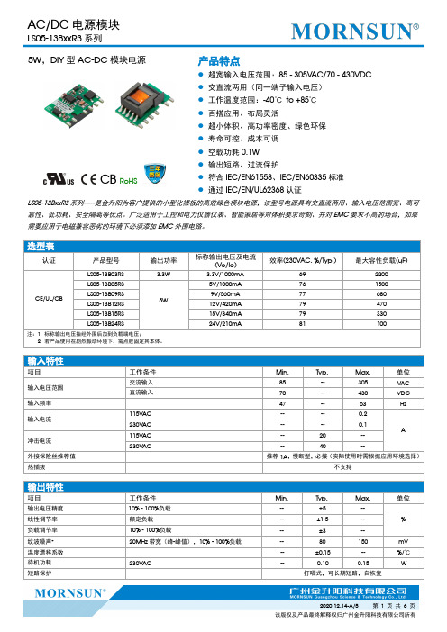
5W,DIY型AC-DC 模块电源CB RoHS产品特点●超宽输入电压范围:85-305VAC/70-430VDC ●交直流两用(同一端子输入电压)●工作温度范围:-40℃to +85℃●百搭应用、布局灵活●超小体积、高功率密度、绿色环保●寿命可控、成本可调●空载功耗0.1W ●输出短路、过流保护●符合IEC/EN61558、IEC/EN60335标准●通过IEC/EN/UL62368认证LS05-13BxxR3系列-----是金升阳为客户提供的小型化裸板的高效绿色模块电源,该型号电源具有交直流两用、输入电压范围宽、高可靠性、低功耗、安全隔离等优点。
广泛适用于工控和电力仪器仪表、智能家居等对体积要求苛刻、并对EMC 要求不高的场合,如果需要应用于电磁兼容恶劣的环境下必须添加EMC 外围电路。
输入特性项目工作条件Min.Typ.Max.单位输入电压范围交流输入85--305VAC 直流输入70--430VDC 输入频率47--63Hz输入电流115V AC ----0.2A230V AC ----0.1冲击电流115V AC --20--230V AC--40--外接保险丝推荐值推荐1A ,慢断型,必接(实际使用时需根据应用环境选择)热插拔不支持输出特性项目工作条件Min.Typ.Max.单位输出电压精度10%-100%负载--±5--%线性调节率额定负载--±1.5--负载调节率10%-100%负载--±3--纹波噪声*20MHz 带宽(峰-峰值),10%-100%负载--80150mV 温度漂移系数--±0.15--%/℃待机功耗230V AC--0.100.15W短路保护打嗝式,可长期短路,自恢复选型表认证产品型号输出功率标称输出电压及电流(Vo/Io)效率(230VAC,%/Typ.)最大容性负载(uF)CE/UL/CBLS05-13B03R3 3.3W3.3V/1000mA 692200LS05-13B05R35W5V/1000mA 761500LS05-13B09R39V/560mA 77680LS05-13B12R312V/420mA 79470LS05-13B15R315V/340mA 79330LS05-13B24R324V/210mA81100注:1.标称输出电压指经外围后加到负载端电压;2.若产品使用在剧烈振动环境下,需点胶固定其本体。
格力LH系列螺杆式水冷冷水机组r

目录珠海格力电器简介.................................................................................................................................质量体系..................................................................................................................................................制造商资格声明.....................................................................................................................................设计方案.........................................................................................................................................一、空调计算参数........................................................................................................................二、空调使用区域设计负荷......................................................................................................三、空调系统设计说明及设备选型.........................................................................................四、产品概述 ................................................................................................................................五、格力中央空调施工方案......................................................................................................六、售后服务承诺书 ...................................................................................................................七、湖南螺杆机部分用户 ........................................................................................................珠海格力电器简介珠海格力电器股份有限公司是目前全球最大的集研发、生产、销售、服务于一体的专业化空调企业,“格力”空调是中国空调行业唯一的“世界名牌”。
LTC3605资料

PVIN, SVIN, SW Voltage.............................. –0.3V to 15V PVIN, SW Transient Voltage ........................ –2V to 17.5V BOOST Voltage .......................... –0.3V to PVIN + INTVCC RUN Voltage ............................................. –0.3V to SVIN VON Voltage............................................... –0.3V to SVIN INTVCC Voltage.......................................... –0.3V to 3.6V ITH, RT, CLKOUT, PGOOD Voltage ......... –0.3V to INTVCC CLKIN, PHMODE, MODE Voltage .......... –0.3V to INTVCC TRACK/SS, FB Voltage .......................... –0.3V to INTVCC Operating Temperature Range (Note 2)....–40°C to 85°C
1
60
50
40 30
VOUT = 3.3V VOUT = 1.2V
0
20
10
0
0.1
10
100
1000
10000
OUTPUT CURRENT (mA)
- 1、下载文档前请自行甄别文档内容的完整性,平台不提供额外的编辑、内容补充、找答案等附加服务。
- 2、"仅部分预览"的文档,不可在线预览部分如存在完整性等问题,可反馈申请退款(可完整预览的文档不适用该条件!)。
- 3、如文档侵犯您的权益,请联系客服反馈,我们会尽快为您处理(人工客服工作时间:9:00-18:30)。
LR 5360, LS 5360, LY 5360, LG 53605 mm (T1 ¾) LED, DiffusedLR 5360 abgek ündigt nach PD_078_02 - wird durch LS 5360 ersetzt werdenLR 5360 obsolete acc. to PD_078_02 - will be replaced by LS 53602003-08-111Besondere Merkmale•Geh äusetyp: eingef ärbtes, diffuses 5 mm (T1¾) Geh äuse•Besonderheit des Bauteils: L ötspie ße mit Aufsetzebene•Wellenl änge: 645nm (rot),628nm (super-rot), 587nm (gelb), 570nm (gr ün)•Abstrahlwinkel: 50°•Technologie: GaAlP•optischer Wirkungsgrad: 0,4lm/W (rot), 1,5lm/W (super-rot, gelb), 2,5lm/W (gr ün)•Gruppierungsparameter: Lichtst ärke •L ötmethode: Wellenl öten (TTW)•Verpackung: Sch üttgut, gegurtet lieferbar Anwendungen•optischer Indikator•Hinterleuchtung (LCD, Handy, Schalter, Tasten, Displays, Werbebeleuchtung, Allgemeinbeleuchtung)•Innenbeleuchtung im Automobilbereich (z.B. Instrumentenbeleuchtung, u.ä.)•Allgemeinbeleuchtung•Signal- und SymbolleuchtenFeatures•package: colored, diffused 5 mm (T1¾) package•feature of the device: solder leads with stand-off•wavelength: 645nm (red),628nm (super-red), 587nm (yellow), 570nm (green)•viewing angle: 50°•technology: GaAlP•optical efficiency: 0.4lm/W (red),1.5lm/W (super-red, yellow),2.5lm/W (green)•grouping parameter: luminous intensity •soldering methods: TTW soldering •packing: bulk, available taped on reel Applications•optical indicators•backlighting (LCD, cellular phones, switches, keys, displays, illuminated advertising, general lighting)•interior automotive lighting. (e.g. dashboard backlighting, etc.)•general lighting•signal and symbol luminaire2003-08-112s LR 5360 abgek ündigt nach PD_078_02 - wird durch LS 5360 ersetzt werdenLR 5360 obsolete acc. to PD_078_02 - will be replaced by LS 5360Letzte Bestellung / Last Order: 30.09.2003Letzte Lieferung / Last Delivery: 31.03.2004Anm.:Die Standardlieferform von Serientypen beinhaltet eine untere bzw. eine obere Familiengruppe odermindestens zwei Einzelgruppen.In einer Verpackungseinheit /Gurt ist immer nur eine Helligkeitsgruppe enthalten.Die technologiebedingte Helligkeits-Streuung der heutigen LED-Herstellprozesse über einen längeren Fertigungszeitraum (Halbleitermaterial - Chipherstellung - Montageprozess) erlaubt keine Zusage einer einzelnen Helligkeitsgruppe. Daher müssen mindestens zwei Helligkeitsgruppen vorgesehen werden!Note:The standard shipping format for serial types includes a lower or upper family group or at least two individual groups.No packing unit /tape ever contains more than one luminous intensity group.Luminosity variations caused by the technology used in current LED manufacturing processes over a protracted manufacturing period (semiconductor material - chip fabrication - assembly process) mean that it is not possible to assign LEDs to a single luminous intensity group. For this reason at least two luminous intensity groups must be provided!Typ TypeEmissions-farbe Color of EmissionGeh äuse-farbe Color of PackageLichtst ärke Luminous Intensity I F = 10mA I V (mcd)Lichtstrom Luminous FluxI F = 10mA ΦV (mlm)Bestellnummer Ordering Codes LR 5360-DG s LR 5360-F s LR 5360-G s LR 5360-FJ red red diffused0.45 ... 2.801.12 ... 1.801.80 ... 2.801.12 ...7.104 (typ.)3 (typ.)5 (typ.)6 (typ.)Q62703Q1376Q62703Q1377Q62703Q1378Q62703Q1379LS 5360-HL LS 5360-J LS 5360-K LS 5360-L LS 5360-JM super-red red diffused2.80 ...18.004.50 ...7.107.10 ...11.2011.20 ...18.004.50 ...28.0035 (typ.)20 (typ.)30 (typ.)50 (typ.)60 (typ.)Q62703Q1380Q62703Q1744Q62703Q1381Q62703Q1382Q62703Q3224LY 5360-HL LY 5360-J LY 5360-K LY 5360-L LY 5360-JM yellow yellow diffused2.80 ...18.004.50 ...7.107.10 ...11.2011.20 ...18.004.50 ...28.0035 (typ.)20 (typ.)30 (typ.)50 (typ.)60 (typ.)Q62703Q2000Q62703Q1386Q62703Q2001Q62703Q2404Q62703Q1387LG 5360-GK LG 5360-H LG 5360-J LG 5360-K LG 5360-HLgreen green diffused1.80 ... 11.202.80 ... 4.504.50 ... 7.107.10 ... 11.202.80 ... 18.0020 (typ.)12 (typ.)20 (typ.)30 (typ.)50 (typ.)Q62703Q1391Q62703Q1390Q62703Q1866Q62703Q2012Q62703Q3188Grenzwerte Maximum RatingsBezeichnung Parameter SymbolSymbolWertValueEinheitUnitLR LS, LY, LGBetriebstemperatur Operating temperature range Top– 55 … + 100°CLagertemperaturStorage temperature range Tstg– 55 … + 100°CSperrschichttemperatur Junction temperature Tj+ 100°CDurchlassstrom Forward current IF4540mAStoßstromSurge currentt≤ 10 µs, D = 0.005IFM0.5ASperrspannung1) Reverse voltage VR12VLeistungsaufnahme Power consumptionT A ≤ 25 °CPtot95130mWWärmewiderstand 2) Thermal resistanceSperrschicht/UmgebungJunction/ambientSperrschicht/LötpadJunction/solder pointMontage auf PC-Board FR 4 (Padgröße ≥ 16mm2) mounted on PC board FR 4 (pad size ≥ 16 mm 2) Minimale BeinchenlängeMinimum lead length Rth JARth JS400180K/WK/W1)für kurzzeitigen Betrieb geeignet / suitable for short term application2)Rtherhöht sich um 13K/W pro mm Beinchenlänge.Each additional 1mm of lead length increases Rthby 13K/W.2003-08-1132003-08-114Kennwerte (T A = 25 °C)Characteristics Bezeichnung ParameterSymbol SymbolWert Value Einheit UnitLRLS LY LG Wellenl änge des emittierten Lichtes (typ.)Wavelength at peak emission I F = 10mAλpeak660635586572nmDominantwellenl änge 1)(typ.)Dominant wavelength I F = 10mAλdom645628587570nmSpektrale Bandbreite bei 50 % I rel max (typ.)Spectral bandwidth at 50 % I rel max I F = 10mA∆λ35454525nmAbstrahlwinkel bei 50 % I V (Vollwinkel)(typ.)Viewing angle at 50 % I V 2ϕ50505050Grad deg.Durchlassspannung 2)(typ.)Forward voltage (max.)I F = 10mA V F V F 1.61.9 2.0 2.5 2.0 2.5 2.0 2.5V VSperrstrom(typ.)Reverse current (max.)V R = 12 VI R I R 0.01100.01100.01100.0110µA µATemperaturkoeffizient von λpeak (typ.)Temperature coefficient of λpeak I F = 10mA; –10°C ≤ T ≤ 100°C TC λpeak0.030.110.100.11nm/KTemperaturkoeffizient von λdom (typ.)Temperature coefficient of λdom I F = 10mA; –10°C ≤ T ≤ 100°C TC λdom0.060.070.070.07nm/KTemperaturkoeffizient von V F (typ.)Temperature coefficient of V F I F = 10mA; –10°C ≤ T ≤ 100°C TC V– 1.4– 1.9– 1.9– 1.4mV/KOptischer Wirkungsgrad (typ.)Optical efficiency I F = 10mAηopt0.4 1.5 1.5 2.5lm/W1)Wellenl ängen werden mit einer Stromeinpr ägedauer von 25ms und einer Genauigkeit von ±1nm ermittelt.Wavelengths are tested at a current pulse duration of 25ms and a tolerance of ±1nm.2)Spannungswerte werden mit einer Stromeinpr ägedauer von 1ms und einer Genauigkeit von ±0,1V ermittelt.Voltages are tested at a current pulse duration of 1ms and a tolerance of ±0.1V.2003-08-115Helligkeitswerte werden mit einer Stromeinpr ägedauer von 25ms und einer Genauigkeit von ±11% ermittelt.Luminous intensity is tested at a current pulse duration of 25ms and a tolerance of ±11%.Helligkeits-Gruppierungsschema Luminous Intensity Groups LichtgruppeLuminous Intensity Group Lichtst ärkeLuminous Intensity I V (mcd)Lichtstrom Luminous Flux ΦV (mlm)D E F G H J K L M0.45 …0.710.71 … 1.121.12 … 1.801.80 … 2.802.80 … 4.504.50 …7.107.10 …11.2011.20 …18.0018.00 …28.002 (typ.)3 (typ.)5 (typ.)7 (typ.)11 (typ.)20 (typ.)30 (typ.)45 (typ.)70 (typ.)Relative spektrale Emission I rel = f (λ), T A = 25 °C, I F = 10mA Relative Spectral EmissionV(λ) = spektrale AugenempfindlichkeitAbstrahlcharakteristik I rel = f (ϕ)Radiation Characteristic2003-08-116Durchlassstrom I F = f (V F)Forward CurrentFf (T) Max. Permissible Forward CurrentRelative Lichtstärke I V/I V(10mA) = f (I F) Relative Luminous IntensityFf (T) Max. Permissible Forward CurrentLR2003-08-117Relative Lichtstärke I V/I V(25 °C) = f (T A) Relative Luminous IntensityZulässige Impulsbelastbarkeit I F = f (t p) Permissible Pulse Handling Capability2003-08-118MaßzeichnungPackage OutlinesMaße werden wie folgt angegeben: mm (inch) / Dimensions are specified as follows: mm (inch). Kathodenkennung:kürzerer LötspießCathode mark:short solder leadGewicht / Approx. weight:0.35 g2003-08-119LötbedingungenSoldering ConditionsWellenlöten (TTW)(nach CECC 00802)TTW Soldering(acc. to CECC 00802)Empfohlenes Lötpaddesign Wellenlöten (TTW)Recommended Solder Pad TTW SolderingMaße werden wie folgt angegeben: mm (inch) / Dimensions are specified as follows: mm (inch). 2003-08-1110LR 5360, LS 5360, LY 5360, LG 53602003-08-1111Published by OSRAM Opto Semiconductors GmbHWernerwerkstrasse 2, D-93049 Regensburg© All Rights Reserved.Attention please!The information describes the type of component and shall not be considered as assured characteristics.All typical data and graphs are basing on representative samples, but don ’t represent the production range. If requested,e.g. because of technical improvements, these typ. data will be changed without any further notice.Terms of delivery and rights to change design reserved. Due to technical requirements components may contain dangerous substances. For information on the types in question please contact our Sales Organization.If printed or downloaded, please find the latest version in the Internet.PackingPlease use the recycling operators known to you. We can also help you – get in touch with your nearest sales office.By agreement we will take packing material back, if it is sorted. You must bear the costs of transport. For packing material that is returned to us unsorted or which we are not obliged to accept, we shall have to invoice you for any costs incurred.Components used in life-support devices or systems must be expressly authorized for such purpose! Critical components 1 may only be used in life-support devices or systems 2 with the express written approval of OSRAM OS.1 A critical component is a component used in a life-support device or system whose failure can reasonably be expected to cause the failure of that life-support device or system, or to affect its safety or the effectiveness of that device or system.2 Life support devices or systems are intended (a) to be implanted in the human body, or (b) to support and/or maintain and sustain human life. If they fail, it is reasonable to assume that the health of the user may be endangered.Revision History:2003-08-11Date of change Previous Version:2002-11-22PageSubjects (major changes since last revision)3thermal resistance (footnote)10annotations 2002-07-255luminous intensity groups 2002-07-303, 4value (reverse voltage from 5V to 12V)2002-09-18allred: not for new designs 2002-11-221, 2red: obsolete 2003-08-11。