ASD-PU-01A数字操作器安装说明书
开关机器人操作器手册说明书
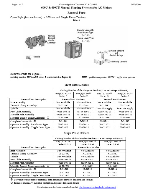
Open Style (less enclosure) - 3 Phase and Single Phase DevicesFigure 1Renewal Parts for Figure 1(catalog number 609U-AOD series F is illustrated in Figure 1) 609U = pushbutton operator 609TU = toggle lever operatorThree Phase DevicesCatalog Number of the Complete Device (** = coil voltage suffix code)609(T)U-AO** Series F 609(T)U-BO** Series F 609(T)U-AO** Series G 609(T)U-BO**Series GRenewal Part Description Renewal Part Numbers Renewal Part NumbersBase Assembly Not Available Not Available Not Available Not AvailableTerminal Clamp Assembly X-225492 X-225492 X-225492 X-225492 Spindle Not Available Not Available Does Not Apply Does Not Apply Pawl Slide Assembly 40189-300-51 40189-300-51 40189-300-51 40189-300-51 Movable Pole Assembly 40189-305-51 40189-305-51 40189-305-51 40189-305-51Movable Contact Carrier Assembly !X-331099 X-331096 X-331099 X-331096 Complete Contact Kit "Z-31911 Z-31913 Z-31911 Z-31913 Operator Assembly: Pushbutton Type X-471623 X-471623 X-471623 X-471623 Operator Assembly: Toggle Lever Type X-471625 X-471625 X-471625 X-471625Single Phase DevicesCatalog Number of the Complete Device (** = coil voltage suffix code)609(T)U-AOX** Series E-F-G 609(T)U-BOX** Series E-F-G 609(T)U-XOX**Series E-F-GRenewal Part Description Renewal Part NumbersBase Assembly Not Available Not Available Not AvailableTerminal Clamp Assembly X-225492 X-225492 X-225492Spindle Not Available Not Available Not AvailablePawl Slide Assembly 40189-300-51 40189-300-51 40189-300-51Movable Pole Assembly 40189-305-51 40189-305-51 40189-305-51Movable Contact Carrier Assembly !X-331099 X-331096 X-331096 Complete Contact Kit "Z-31910 Z-31912 Z-31914 Operator Assembly: Pushbutton Type X-471623 X-471623 X-471623Operator Assembly: Toggle Lever Type X-471625 X-471625 X-471625! Movable contact carrier assembly does not include movable contacts and springs." Includes stationary, movable contacts and springs for entire device.Solenoid (Coil) Assemblies (Includes Mounting Hardware)Cat. No. Coil Suffix Voltage Code Coil Volts - Hz Solenoid (Coil) Renewal Part Number WJ 24V 60 Hz MA-013None 40V 60 Hz MA-219S, XS 110 – 115V 50 Hz MA-322D, XD 115 - 120V 60 Hz MA-236None 127 - 132V 50 Hz MA-328None 152 - 158V 60 Hz MA-289None 166 - 173V 60 Hz MA-245None 174 - 181V 60 Hz MA-246None 192 - 200V 50 Hz MA-337F 201 - 210V 50 Hz MA-338H, XH 200 - 208V 60 Hz MA-249P, XP 220 - 230V 50 Hz MA-339A, XA 230 - 240V 60 Hz MA-254None 252 - 263V 60 Hz MA-257None 317 - 331V 60 Hz MA-263None 364 - 380V 60 Hz MA-267VN 380V 50 Hz MA-354None 384 - 401V 50 Hz MA-355N, WL 415V 50 Hz MA-357None 438 - 459V 60 Hz MA-271Q 440 - 460V 50 Hz MA-360B 460 - 480V 60 Hz MA-273None 481 - 502V 60 Hz MA-274None 527 - 551V 60 Hz MA-276C 550V 50 Hz MA-368C 575 - 600V 60 Hz MA-278Enclosed NEMA Type 1 Bulletin 609U Manual Starting Switches - 3 Phase and Single Phase DevicesEnclosure Only for 609U-AAD (does not include manual starting switch)Renewal Part Number 40189-806-01Manual Starting Switch – 609U-AOD609U = pushbutton operator 609TU = toggle lever operatorCatalog Number of the Complete Device (* = coil voltage suffix code)609U-AA* or 609U-BA* 609TU-AA* or 609TU-BA* 609U-AAX* or 609U-BAX* or 609U-XAX* 609TU-AAX* or 609TU-BAX* or 609TU-XAX*Series F-G Series H Series F-G Series H Renewal Part Description Renewal Part Numbers Renewal Part NumbersEnclosure (base and cover assemblies) 40189-806-01 !40189-806-01 40189-806-01 !40189-806-01 Enclosure Base Only Not Available Not Available Not Available Not Available Enclosure Cover Only Not Available 40189-808-01 Not Available 40189-808-01! This part number is larger than the enclosure used on the original devices.Manual Starting Switches (less enclosure)609U-AOD (609TU devices similar in appearance)Enclosed Switch Cat. No. Renewal Part Number for Manual Switch less Enclosure (* = coil voltage suffix code) 609(T)U-AA* 609(T)U-AO* 609(T)U-AAX* 609(T)U-AOX* 609(T)U-BA* 609(T)U-BO* 609(T)U-BAX* 609(T)U-BOX* 609(T)U-XAX* 609(T)U-XOX*Enclosed NEMA 12 Bulletin 609U Manual Starting Switches - 3 Phase and Single Phase DevicesEnclosure Only for 609U-AJD (does not include manual starting switch) Renewal Part Number 40189-807-01 Cover Pushbutton Assembly Renewal Part Number 40189-062-51Catalog Number of the Complete Device (* = coil voltage suffix code)609U-AJ* or 609U-BJ* 609U-AJX* or 609U-BJX* or 609U-XJX*Series E-H Series J-K Series F-H Series J-K Renewal Part Description Renewal Part Numbers Renewal Part NumbersEnclosure (base and cover assemblies) 40189-807-01 !40189-807-01 40189-807-01 !40189-807-01Enclosure Base Only Not Available Not Available Not Available Not AvailableEnclosure Cover with Cover Pushbuttons Not Available 40189-809-01 Not Available 40189-809-01Cover Pushbutton Assembly Only 40189-062-51 40189-062-51 40189-062-51 40189-062-51! This part number is larger than the enclosure used on the original devices.Manual Starting Switch (less enclosure)Enclosed Switch Cat. No. Renewal Part Number for Manual Switch less Enclosure (* = coil voltage suffix code) 609U-AJ* 609U-AO* 609U-AJX* 609U-AOX* 609U-BJ* 609U-BO* 609U-BJX* 609U-BOX* 609U-XJX* 609U-XOX*Renewal Parts - Enclosed NEMA 4X Bulletin 609U Manual Starting Switches – 3 Phase and Single Phase DevicesEnclosure Only for 609U-ACD (less switch) Renewal Part Number 40189-803-01 Cover Operating MechanismRenewal Part Number 40189-810-01Conduit Hub1490-N9Grounding Adapter1490-N20Catalog Number of the Complete Device (* = coil voltage suffix code)609U-AC* (Sz 0) or609U-BC* (Sz 1)609U-ACX* (Sz 0) or 609U-BCX* (Sz 1)or 609U-XCX* (Sz 1P) Series G-J Series K Series F-H Series JRenewal Part Description Renewal Part Numbers Renewal Part Numbers Enclosure (base and cover assemblies) 40189-802-01 !40189-802-01 40189-802-01 !40189-802-01 Enclosure Base Only Not Available Not Available Not Available Not AvailableEncl. Cover w/ Cover Operating Mech – Sz 0 X-474310 609-ACW-COV Encl. Cover w/ Cover Operating Mech - Sz 1 X-474310 609-BCW-COVX-474310(for sizes 0, 1, 1P)609-ACX-COV(for sizes 0, 1, 1P)Operating Mechanism used in Cover 40189-805-01 40189-803-01 40189-805-01 40189-803-01 Grounding Adapter in Base 1490-N20 1490-N20 1490-N20 1490-N20Conduit Hub in Base 1490-N9 1490-N9 1490-N9 1490-N9! This part number is larger than the enclosure used on the original devices.Manual Starting Switch (less enclosure)609T Manual Switch is illustrated (609TU switch is similar in appearance with addition of solenoid assembly) Enclosed Switch Cat. No. Renewal Part Number for Manual Switch less Enclosure (* = coil voltage suffix code) 609U-AC* 609TU-AO* 609U-ACX* 609TU-AOX* 609U-BC* 609TU-BO* 609U-BCX* 609TU-BOX* 609U-XCX* 609TU-XOX*Renewal Parts -Enclosed NEMA 7&9 and NEMA 3R, 7&9 Bulletin 609U Manual Starting Switches – 3 Phase and Single Phase DevicesEnclosure Only for 609U-AED (less switch) Renewal Part Number X-474312Enclosure Only for 609U-AHD (less switch)Renewal Part Number 40189-800-01Cover Operating MechanismRenewal Part Number 40189-801-01 Catalog Number of the Complete Device (* = coil voltage suffix code) 609U-AE* (Sz 0), 609U-BE*609U-AEX* (Sz 0), 609U-BEX* (Sz 1)609U-AH* (Sz 0), 609U-BH* (Sz 1),609U-AHX* (Sz 0), 609U-BHX* (Sz 1) Series F-H Series ARenewal Part Description Renewal Part Numbers Renewal Part Numbers Enclosure (base and cover assemblies) X-474312 40189-800-01 ! Enclosure Base Only Not Available Not AvailableEnclosure Cover with Cover Operating Mechanism 609-AEW-COV (for Sz 0)609-BEW-COV (for Sz 1)609-BHW-COV(for Size 0 and for size 1 devices)Operating Mechanism used in Cover 40189-804-01 40189-801-01! Does not include drain. Order separately as 1401-N2.Manual Starting Switch (less enclosure)609T Manual Switch is illustrated (609TU switch is similar in appearance with addition of solenoid assembly) Enclosed Switch Cat. No. Renewal Part Number for Manual Switch less Enclosure (* = coil voltage suffix code) 609U-AE* 609TU-AO* 609U-AH* 609TU-AO* 609U-BE* 609TU-BO* 609U-BH* 609TU-BO* 609U-AEX* 609TU-AOX* 609U-AHX* 609TU-AOX* 609U-BEX* 609TU-BOX* 609U-BHX* 609TU-BOX*Important User Information Because of the variety of uses for the products described in this publication, those responsible forthe application and use of this control equipment must satisfy themselves that all necessary stepshave been taken to assure that each application and use meets all performance and safetyrequirements, including any applicable laws, regulations, codes and standards.The illustrations, charts, sample programs and layout examples shown in this guide are intendedsolely for purposes of example. Since there are many variables and requirements associated with anyparticular installation, Rockwell Automation does not assume responsibility or liability (to includeintellectual property liability) for actual use based upon the examples shown in this publication.Allen-Bradley publication SGI-1.1, Safety Guidelines for the Application, Installation and Maintenance ofSolid-State Control (available from your local Allen-Bradley office), describes some importantdifferences between solid-state equipment and electromechanical devices that should be taken intoconsideration when applying products such as those described in this publication.Reproduction of the contents of this copyrighted publication, in whole or part, without writtenpermission of Rockwell Automation, is prohibited.Throughout this document we use notes to make you aware of safety considerations:Identifies information about practices or circumstances that can lead topersonal injury or death, property damage or economic lossIdentifies information that is critical for successful application andunderstanding of the product.Use only replacement parts and devices recommended by Rockwell Automation to maintain theintegrity of the equipment. It is the user’s responsibility to ensure that the renewal part numberselected is properly matched to the model, series and revision level of the equipment being serviced.Servicing energized Industrial Control Equipment can be hazardous.Severe injury or death can result from electrical shock, burn, orunintended actuation of controlled equipment. Recommended practiceis to disconnect and lockout control equipment from power sources,and release stored energy, if present.Refer to National Fire Protection Association Standard No. NFPA70E, Part 2 and (asapplicable) OSHA rules for Control of Hazardous Energy Sources (Lockout/Tagout) andOSHA Electrical Safety Related Work Practices for safety related work practices, includingprocedural requirements for lockout/tagout, and appropriate work practices, personnelqualifications and training requirements where it is not feasible to de-energize and lockout or tagoutelectric circuits and equipment before working on or near exposed circuit parts.ROCKWELL DISCLAIMS ALL WARRANTIES WHETHER EXPRESSED OR IMPLIED INRESPECT TO THE INFORMATION (INCLUDING SOFTWARE) PROVIDED HEREBY,INCLUDING THE IMPLIED WARRANTIES OF FITNESS FOR A PARTICULAR PURPOSE,MERCHANTABILITY, AND NON-INFRINGEMENT. Note that certain jurisdictions do notcountenance the exclusion of implied warranties; thus, this disclaimer may not apply to you.Allen-Bradley is a trademark of Rockwell Automation。
安德森数字压力计与切换设备安装与启动指南说明书

Anderson Instrument Co., Inc.156 Auriesville Rd. ~ Fultonville, NY 12072Phone: 518-922-5315 ~ Fax: 518-922-8997Installation and Startup GuideDigital Pressure Gauge & SwitchVersion 1.4 Document 2052PRODUCT DESCRIPTIONThe Anderson Digital Pressure Gauge platform is designed specifically for monitoring critical pressures in sanitary applications. The product line was developed to addressseveral trends relative to performance, safety, and readability criteria of our core customers. The Anderson Digital Pressure Gauge provides a battery-powered, local display of pressure that is 6 times more accurate than its mechanical counter-part. Additionally, this product has 3 times the over-range capacity and 5-10 times the resolution of traditional mechanical pressure indicators. The switch version includes 2 fully adjustable switches with low-voltage relay outputs for simple control and/or alarming applications.SPECIFICATIONSPerformance Accuracy: ±0.2% of transducer URL (30, 100, 200, 300, 500 psi)±0.5% of transducer URL (5 psi)Complies with ASME B40.7-1998Repeatability: ±0.06% of transducer URL (30, 100, 200, 300, 500 psi)±0.2% of transducer URL (5 psi)Temperature stability: ±0.10 psi / 10ºF change in process orambient Over-range Capacity:2X URLOperationalProcess Temp Limits: -4º to 127ºC (25º to 260ºF) continuousAmbient Temp Limits: 4º to 49ºC (40º to 120ºF)Engineering Units: Programmable by user, see matrix for pound ranges: Full Vacuum to selected positive pressure. If set to “HG, display reads in “HG when in the vacuum range and PSIG when there is positive pressure.Min / Max Pressure: Captured and stored in non-volatile memory, may be cleared via tamper- resistant toggle.ElectricalPower: 2 “AA” replaceable batteries with one- year minimum expected life with industrial grade batteries (gauge only); 9-30 Volts external DC power (with switches) with battery back-up of non- volatile programmed values.Relay Outputs (Switch only): Two (2) independent, adjustable setpoint relays: One amp contact rating at 24 volts DC, SPST; Contacts open with no power to unit (failsafe) each programmable to close above or below setpoint.Mechanical Display: LCD, with 0.9” height Wetted Material: 316 “L” Stainless Steel, welded and polished to max R a = 8 microinches (0.2 microns) for EP aand max R a = 25 microinches for EN.Housing: 304 Stainless Steel, welded Lens: Polysulphone Approvals and DocumentationSanitary: Meet current ASME BPE-2002 standards; Authorized to display the 3-A Symbol, Third Party Verified.PED: Complies with the Pressure Equipment Directive relative to Sound Engineering Practices.Electrical: Tested to IEC 61326 Standard for Emissions and Immunity in Industrial locations.Enclosure: Meets or exceeds requirements for NEMA 4X.Hazardous Locations: UL for Intrinsically Safe requirements pending.Material, Conformance and Calibration: Certificates provided with product also available on-line using serial number (applies to EPonly).READ THIS FIRSTA three segment battery indicator allows the operator to monitor battery life of the DPG, and plan ahead for a battery change. When a low threshold is reached, the final indicator bar blinks on and off. Internal circuitry regulates battery voltages to ensure all factory specifications are met, even with a decrease in battery voltage. When an unacceptable level is reached, the DPG will shut down. Internal flash memory retains all prior calibration, and only replacement of the batteries is required to resume operation.RUN Mode(read values only)Normal Display: Pressure & UnitsAlarm Setpoint and ActionAlarm 1 Hysteresis Alarm 2 Setpoint and ActionAlarm 2 Hysteresis Low Range Limit Upper Range Limit Dampening FactorMaximum Captured Pressure Minimum Captured Pressure Calibration Offset Value Calibration Gain ValueSETPOINTS Mode (modify alarm values)Alarm 1 Setpoint ValueAlarm 1 Action Alarm Hysteresis Alarm 2 Setpoint ValueAlarm 2 Action Alarm 2 HysteresisCALIBRATE Mode(modify field calibration parameters)Calibration Offset Calibration GainPressure Units DisplayedDampening Factor Decimal Point Position Maximum Pressure Captured Minimum Pressure Captured Restore Factory ConfigurationBATTERY REPLACEMENTUSER DISPLAYVALUE Switch UP to increase DOWN to decrease MODE Switch UP for SETPOINTS DOWN for CALIBRATIONDigital Gauge shown with back removed to expose batteries and switches.MENU Switch UP for SCROLL FWD DOWN for SCROLL BACKPrimary Process Display Four digit 0.9” LED with adjustable decimal point position to indicate pressure value.Alarm 1 and 2 Indicators Flashes if setpoint tripped.Displays continuouslyduringsetpoint viewing or programming.Battery Status Indicator Three bars indicatebattery condition is good.Secondary Display Indicates pressure units or parameter information.ALARM SETPOINT PROGRAMMING(MODE Switch in the UP Position)CALIBRATION / CONFIGURATION PROGRAMMING(MODE Switch in the DOWN Position)PSI Gau, PSI ABS, in 2H 0, Kg/cm , mmHg, 2inHg, MP a, kP a, Bar Digital Filter settable from 0.0 to 10.0(no dampening = 0.0)Decimal point position.(Setting is not stored in non-volatile memory)Hold UP switch for 3seconds to reset.Hold UP switch for 3 seconds to reset.Hold UP switch for 3 seconds to reset all factory defaults.Span calibrationadjustment.Multiplies reading.Range: 0.90-1.10Offset calibrationadjustment.Adds to reading. Range: +/- 10% of SpanCalibration mode.MENU SCROLL BACK to proceed.(MODE Switch in the UP position)(MODE Switch in the DOWN position)Compound Ranges with units set to inHG, or mmHG will read PSIG if measuring positive pressure.Gauge (G, M, B, C) and Absolute(A) pressure units may not be interchanged, and must match original hardware configuration.Calibration mode.MENU SCROLL BACK to proceed.Offset calibration adjustment.Adds to reading.Range +/- 10% of Span Span calibration adjustment.Multiplies reading.Range: 0.90-1.10PSI Gau, PSI ABS, in H 20, Kg/cm 2, mmHg,inHg, MPa, kPa, Bar Compound Ranges withunits set to inHG, or mmHG will read PSIG if measuring positive pressure.Gauge (G, M, B, C) and Absolute (A) pressure units may not be interchanged, and must match original hardware configuration.Digital Filter settable from 0.0 to 10.0(no dampening = 0.0)Hold UP switch for 3seconds to reset.Hold UP switch for 3seconds to reset.Hold UP switch for 3seconds to reset all factory defaults.Decimal point position.(Setting is not stored in non-volatile memory)PSI Gau, PSI ABS, in 2H 0, Kg/cm , mmHg, 2inHg, MP a, kP a, Bar Digital Filter settable from 0.0 to 10.0(no dampening = 0.0)Decimal point position.(Setting is not stored in non-volatile memory)Hold UP switch for 3 seconds to reset.Hold UP switch for 3 seconds to reset.Hold UP switch for 3 seconds to reset all factory defaults.Span calibration adjustment.Multiplies reading.Range: 0.90-1.10Offset calibration adjustment.Adds to reading.Range: +/- 10% of Span Calibration mode.MENU SCROLL BACK to proceed.(MODE Switch in the UP position)(MODE Switch in the DOWN position)RELAY WIRING (DIGITAL PRESSURE SWITCH ONLY)DIMENSIONAL DRAWINGS9-30 VDC, 250 mA typical external power required toenergize relays.ConnectorRetaining RingConnector HousingSeal GrommetCompressionRingPressing ScrewConnector EndPin 3 - GREEN (Relay Common)Pin 2 - BLACK(-PWR)Pin 1 - RED(+ PWR 9-30 VDC)Pin 5 - WHITE (Relay 2 N.O.)Pin 4 - BLUE (Relay 1 N.O.)Normally Open relay contactsrated for 1 amp max. at 24VDC.(Not suitable for AC voltage)Digital Pressure Switch must be externally powered to utilize relays.CABLE REQUIREMENTS• 5 conductor, standard, 18-24 AWG,.•4-8 mm (0.16-0.31”) Cable Sheath ODConnector p/n: 42119A0000(Turck eurofast®, 5-wire, 5-pin, female)5.84.21.83.64.21.84.83.45。
AELTA 数位操作器 ASD-PU-01A 各部说明

進入參數設定模式;儲存參數設定值; 在診斷功能中,在最後一個步驟用來 執行該項功能
快速編輯 提供三種功能使用,包括參數快速編輯、 靜態與動態自動增益計算
參數儲存 將驅動器的參數儲存至數位操作器
4 驅動器與數位操作器 Keypad 通訊線
FEDIT:AUTO D -T 16 s
FEDIT:AUTO D -L 7
靜態自動增益
MODE
FEDIT:AUTO S
FEDIT:AUTO S
MODE
Fast Edit
FEDIT:AUTO S -BW 100 HZ
Fast Edit
FEDIT:AUTO S -JR 1.0 HZ
Fast Edit
FEDIT:AUTO S -RH 1.000 HZ
Fast Edit
FEDIT:AUTO D -F 1.0 HZ
Fast Edit
FEDIT:AUTO D -T 15 s
Fast Edit
MODE
FEDIT:AUTO D -L 6
Fast Edit
FEDIT:AUTO D -L PR Dload
FEDIT:AUTO D -R 3 HZ
FEDIT:AUTO D -F 1.1 HZ
請依照指定的方式搭配伺服驅動器,否則可能會導致故障。
安裝注意 禁止將本產品暴露在有水氣、腐蝕性氣體、可燃性氣體等物質的 場所下使用,否則可能會造成故障。
配線注意
請注意接線兩端的裝配方向,否則可能造成故障。
操作注意
請勿大力摔放、敲打,或是不當方式操作,否則可能造成故障。
維護及檢查 請勿自行拆解本產品,或是任意破壞線材外觀,否則可能造成產品 損壞。
操作器使用说明书

操作器的使用说明书一、功能介绍1、此操作器具有0~9共10数字,通过这10个数字键进行密码的设定和ID的匹配。
2、此操作器配备了急停(STOP)按钮,应急情况下停止设备信号输出。
3、此操作器设置了上升按钮(↑)和下降按钮(↓),当操作器被启动后点击此按钮就会输出相应的动作信号。
二、用户操作使用说明操作器编程完成后,进入正常工作使用状态,红灯亮,绿灯和橙灯熄灭。
使用方法如下:1. 将用户卡接近一操作器或输入4位用户开启密码,蜂鸣器长鸣一声,绿灯亮,红灯熄灭,开启成功,在设定的开启时间内,灯指示状态不变。
如果在设定的时间内用户想关闭操作器则可以再次刷卡或按“*”键。
2. 如果蜂鸣器短鸣三声,红灯连续闪亮三次,则表示该卡或密码为非法用户,不能开器操作器。
3. 如果用户想重新设置操作器的参数请仔细阅读管理员操作使用说明或联系管理员或厂家。
三、管理员操作使用说明1、操作器的数据参数2、操作器的安装说明(1)固定于金属框架上:取下底板,根据底板预留好的安装孔的距离在金属框上画好线,根据结构选用相应的工具进行打孔攻丝。
使用M4螺栓固定。
安装时请注意操作器的上下方向。
3、固定于墙面上:取下底板,根据底板预留好的安装孔的距离在墙面上画好线,根据结构选用相应的工具进行打孔。
使用¢5的膨胀管固定。
安装时请注意操作器的上下方向。
4、端子接线图5、操作器的设置(1)、“#”键:功能键,进入编程模式①按“#”字键,红灯、绿灯齐闪亮。
②输入5位系统密码(出厂密码:12345),蜂鸣器鸣响一声,红灯和橙灯亮、绿灯熄灭,门禁机进入系统编程状态。
(2)、“1”键,修改系统密码①按“1”字键,橙灯亮,红灯和绿灯熄灭。
②用户输入5位数字密码(如:88888),输入完毕,蜂鸣器短鸣一声,绿灯闪亮一次熄灭,橙灯和红灯亮,密码修改成功。
注意:该系统密码用户需妥善保存,再次进入系统编程模式时需要输入该系统密码,如果忘记密码,请执行初始化操作。
达实DAS电梯控制器使用手册

InDAS建筑智能化解决方案资料修改记录表序号:页号:修改日期:InDAS建筑智能化解决方案电梯控制器使用手册(第一版)深圳达实智能股份有限公司2006年12月手册用途本手册包含电梯控制器产品功能介绍、产品说明、产品调试、常见故障及诊断和技术参数等内容,供用户和技术人员参考使用,用户在使用本产品前务必先阅读本手册。
本手册版权归深圳达实智能股份有限公司所有。
产品的发行和销售由原始购买者在许可协议条款下使用。
未经深圳达实智能股份有限公司允许,任何单位和个人不得将该手册全部或部分复制、或者还原成其它机器可读形式的电子媒介。
本手册若有任何修改恕不另行通知。
本手册最终解释权归深圳达实智能股份有限公司所有。
第1章产品功能介绍1.1 产品简介本电梯控制器采用非接触式IC/ID 卡感应技术进行身份识别,可实现人员进出电梯的控制。
支持WG读头和485读头,当持卡人进入电梯后,在感应器上刷卡,电梯控制器判断此卡是否有权限、时限,如果有权则允许登梯,无权不能登梯。
对于只有单层权限的用户,刷卡后无须按键,电梯直达用户有权限的那一楼层,对于具有多层权限的用户,刷卡后电梯控制器释放用户有权限的楼层按键,等待用户按键(等待时间5—6秒)。
电梯控制器主板可控制16个楼层,增加一块扩展板可增加控制16个楼层,总共可控制32个楼层,如果楼层在16层以内,就不需要增加扩展板。
本电梯控制器与计算机之间采用RS-485 方式通讯,还可与中继器配合使用,灵活组成不同应用规模的电梯控制系统。
1.2 产品功能特点•读头支持WG读头和485读头,WG读头接口,能够智能识别标准WIEGAND 26/32/40协议格式,485读头接口只能接公司生产的485读头,读头接口提供5VDC 或12VDC 读头工作电源,兼容性强;•兼容多种技术生物识别技术、指纹识别技术、密码键盘、感应式IC、ID卡;•乘梯验证方式验证权限时限乘梯,无权或者不在有限时限内不能乘电梯;•远程控制可以远程控制电梯到达某一层;•时限灵活设置支持256个时间段,16个时间组,128个节假日;•定时启用、关闭电梯控制器支持非节假日定时启用、关闭电梯控制器,在关闭状态下无须刷卡即可乘电梯;•消防联动接收一路常闭消防联动输入信号,当消防信号启动后,电梯控制器屏蔽刷卡功能,电梯恢复到原状态,即不需要刷卡就可以乘电梯(提供的消防信号应该是无源的干接点信号),消防信号输入端口在出厂时已短接;•脱机工作采用“分散控制、集中管理”的原则设计,设定好控制器的参数、权限、时限后,各控制器可脱离通讯网络和管理计算机单独运行,可靠性高;•掉电保护采用先进的NRAM 实时时钟模块,掉电后时钟不紊乱,记录数据采用EEPROM存储,掉电后数据可保存10 年不变;•双隔离电源配有专用电源,两组独立回路供电,内部电路和外部电路使用不同电源,稳定性好,抗干扰性强,可靠性高;•有源隔离通讯通讯接口采用有源隔离方式,减少通讯干扰;第2章产品说明2.1 系统结构2.2 电梯控制器主板接口图主板接口图2.2.1 电梯控制器主板接口说明① J1~J4:第1层~16层楼层信号输出端每个楼层输出信号由A 、B 、C 三端组成,如下图所示:② J5:扩展总线输出接口该接口用于连接扩展板,与扩展板上的扩展总线输入端(J5)相连。
Schneider Automation S.A.S. 磁性操作员终端安装指南说明书

How to install Magelis operator terminals forMerchant Navies applicationsSchneider Automation SASSubsidiary of Schneider Electric06516 Carros - FranceD ISCLAIMERInstructions provided in this Technical Resolution do not substitute to Merchant Navies Rules applicable in ship manufacturing or ship maintenance & installation.R ELEVANT S TANDARDSThese devices have been manufactured in accordance with:•IACS-E10•IEC 60945 with selection of applicable sections•IEC 60092-504 with selection of applicable sections•IEC 61174 with selection of applicable sectionsWe cannot accept any responsibility for failure to observe these regulations.R ELEVANT P RODUCTSThese recommendations relate to matrix and graphic terminals intended for installation for Merchant Navies applicationsG ENERAL I NSTALLATION I NSTRUCTIONSMake sure that you follow all the recommendations in the User Manuals and especially those listed belowM ERCHANT N AVIES I NSTALLATION I NSTRUCTIONSGeneralOnly analogue, digital and telecommunication signal pairs can be bound one against the other in one bundle or run in the same bundled cable.The relay, variator, supply and power circuits must be separated from the pairs above.Take special care when setting up the speed variators to separate the power connections from the data connections.Check IP Code (Degrees of protection provided by enclosures) compliance of your installationSchneider Automation S.A.S.8eme Rue - ZI de Carros Societe par Actions Simplifiée au capital de 247. 251,95 €Schneider Automation S.A.S.8eme Rue - ZI de CarrosSociete par Actions Simplifiée au capital de 247. 251,95 €XBT N/R M ATRIX T ERMINALSFor installation on GENERAL PURPOSE DISTRIBUTION ZONETo comply with EMC requirements GENERAL PURPOSE DISTRIBUTION ZONE, products must be installed with accessories detailed in the table below:Products Instructions for InstallationAll XBT N All XBT R Serial link cable, Printer cable and Power supply cable must be fittedwith Würth 74271222 type snap ferriteFor installation on the BRIDGE.To comply with EMC requirements for BRIDGE, products must be installed with accessories detailed in the table below:Products Instructions for InstallationAll XBT N All XBT R • Serial link cable, Printer cable and Power supply cable must be fitted with Würth 74271222 type snap ferrite• Terminal must be installed five meters away from thecompass as required in 11.2 of IEC60945.24VDC power supplied terminals : XBT R410 XBT R411 XBT N401 XBT N410XBT NU400• Power supply cable fitted (in series with supply terminals) with Schaffner FN680-1/06 type filter.• Terminal must be installed five meters away from the compass as required in 11.2 of IEC60945.Schneider Automation S.A.S.8eme Rue - ZI de CarrosSociete par Actions Simplifiée au capital de 247. 251,95 €G RAPHIC XBT GT, HMI STU and HMI STO T ERMINALSFor installation on GENERAL PURPOSE DISTRIBUTION ZONETo comply with EMC requirements for GENERAL PURPOSE DISTRIBUTION ZONE, productsmust be installed with accessories detailed in the table below: Products Instructions for InstallationXBT GT1100 / 1130 No specific instructionXBT GT2330 / 2340 XBT GT4330 / 4340 XBT GT5330 / 5340 XBT GT6330 / 6340 XBT GT7340• Power supply cable must be fitted (in series with supply terminals) with Schaffner FN2070-1/06 type filter.• Product must be mounted in a grounded metallic enclosure. • Shield of Power supply cable, AUX cable and USB cables must be groundedFor installation on the BRIDGETo comply with EMC requirements for BRIDGE, products must be installed with accessoriesdetailed in the table below: Products Instructions for InstallationXBT GT 1100 XBT GT 1130 • Power supply cable must be fitted (in series with supply terminals) with Schaffner FN680-1/06 type filter.• Terminal must be installed five meters away from the compass as required in 11.2 ofIEC60945.• HMI application must be designed to not degrade the night vision of the officer of the watchConfiguration software offers the possibility to tune brightness/contrast and applicationpanel colours to comply with Ergonomic requirements based on IEC60945 for Bridge.HMI STU 655 HMI STU 855 • Power supply cable must be fitted (in series with supply terminals) with Schaffner FN2010 type filter.• Terminal must installed five meters away from the compass as required in 11.2 ofIEC60945.• HMI application must be designed to not degrade the night vision of the officer of the watch.Configuration software offers the possibility to tune brightness/contrast and applicationpanel colours to comply with Ergonomic requirements based on IEC60945 for Bridge.HMISTO501 HMISTO511 HMISTO512 • Power supply cable must be fitted (in series with supply terminals) with Schaffner FM2070-3–06 type filter.• Terminal must installed five meters away from the compass as required in 11.2 ofIEC60945.• HMI application must be designed to not degrade the night vision of the officer of the watch.Configuration software offers the possibility to tune brightness/contrast and applicationpanel colours to comply with Ergonomic requirements based on IEC60945 for Bridge.Schneider Automation S.A.S.8eme Rue - ZI de CarrosSociete par Actions Simplifiée au capital de 247. 251,95 €G RAPHIC HMIGTO T ERMINALSFor installation on GENERAL PURPOSE DISTRIBUTION ZONETo comply with EMC requirements for GENERAL PURPOSE DISTRIBUTION ZONE, productsmust be installed with accessories detailed in the table below:Products Instructions for InstallationHMI GTO 1300 /1310 HMI GTO 2300 / 2310 HMI GTO 3510HMI GTO 4310• A filter of Schaffner type FN2070-3-06 or equivalent is to be installed inside the 24VDC power line.HMI GTO 5310 HMI GTO 6310• No specific instructionFor installation on the BRIDGETo comply with EMC requirements for BRIDGE, products must be installed with accessoriesdetailed in the table below: Products Instructions for InstallationHMI GTO 1300 /1310 HMI GTO 2300 / 2310 HMI GTO 3510 HMI GTO 4310 • A filter of Schaffner type FN2070-3-06 or equivalent is to be installed inside the 24VDC power line.• The product is to be placed inside the metal enclosure. • Terminal must be installed five meters away from the compass as required in11.2 of IEC60945.• HMI application must be designed to not degrade the night vision of the officerof the watch Configuration software offers the possibility to tunebrightness/contrast and application panel colours to comply with Ergonomicrequirements based on IEC60945 for Bridge.HMI GTO 5310 HMI GTO 6310 • The product is to be placed inside the metal enclosure.• Terminal must installed five meters away from the compass as required in 11.2of IEC60945.• HMI application must be designed to not degrade the night vision of the officerof the watch. Configuration software offers the possibility to tunebrightness/contrast and application panel colours to comply with Ergonomicrequirements based on IEC60945 for Bridge.Schneider Automation S.A.S.8eme Rue - ZI de CarrosSociete par Actions Simplifiée au capital de 247. 251,95 €• Industrial PC and associated displayFor installation on the GENERAL PURPOSE DISTRIBUTION ZONE and BRIDGETo comply with EMC requirements, products must be installed with accessories detailed in the table below: Products Instructions for InstallationBox PC HMIBUxND1xx1 HMIBUxND2xx1 HMIPCCB1B1B HMIPCCB1B2B HMIPCCB1B1B• Power supply cable must be fitted (in series with supply terminals) with HMIYLFIMAR11 filter. (see Schneider catalogue)• Product must be installed five meters away from the compass as required in 11.2 of IEC60945. Panel PC HMIPUx7D0xx1 HMIPUx9D0xx1 HMIPCCP170B HMIPCCP180B • Power supply cable must be fitted (in series with supply terminals) with HMIYLFIMAR11 filter. (see Schneider catalogue)• Product must be installed five meters away from the compass as required in 11.2 of IEC60945. • HMI application must be designed to not degrade the night vision of the officer of the watch Configuration software offers the possibility to tune brightness andapplication panel colours to comply with Ergonomic requirements based onIEC60945 for Bridge.Display HMIDID7DT0 • HMIDID7DT0 must be connected to marine certified Schneider Box PC• Power supply cable must be fitted (in series with supply terminals) with SchaffnerFN2070-3–06 or FN670-1.8-06 type filter.• Display must be installed five meters away from the compass as required in 11.2 ofIEC60945.• HMI application must be designed to not degrade the night vision of the officer of thewatch. Configuration software offers the possibility to tune brightness/contrast andapplication panel colours to comply with Ergonomic requirements based onIEC60945 for Bridge.。
西门子前端巴拉连接器安装说明说明书
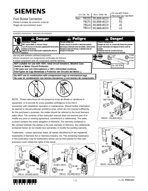
sFront Busbar ConnectionPiezas frontales de conexión a barras Plages de raccordement avantInstallation Instructions / Instructivo de InstalaciónUse only with Siemens certified Components.Utilizar únicamente con componentes certificados de Siemens.A utiliser uniquement avec les composants certifiés Siemens .Turn off and lock out all power supplying this device before Couper Tensión Tension dangereuse.Hazardous Voltageworking on this device.Replace all covers before power supplying this device is turned on.l'alimentation de l'appareil et barrer avant de travailler.Remplacez touts les couverts avant que l'approvisionnement de pouvoir soit alimenté.peligrosa.Puede causar la muerte o lesiones graves.Danger de mort ou risque de blessures graves.Will cause death or serious injury Desenergice totalmente antes de instalar o darle servicio. Reemplace todas las barreras y cubiertas antes de energizar el interruptor.Item: FBCD3FBCF3FBCJ3FBCL3U.S. Cat. No.Euro Order No.3VL9200-4EC313VL9300-4EC313VL9400-4EC313VL9460-4EC31Cal. ISO 67895 mm6 mm 8 mmNOT suitable for use with 100% rated circuit breakers, Molded Case Switch or Motor Circuit Protector.[ NO para uso con interruptores a 100% intensidad continua, Interruptor de Caja Moldeada o Protector del Circuito del Motor. ]DGFBCD3 / 3VL9200-4EC313X M6 X 20mm3X 3XFGFBCF3 / 3VL9300-4EC313X M8 X 20mm3X 3XDo NOT use in combination with compression lugs or mechanical lugs.No usar en combinación con bornes mecánicos o con bornes de compresión.NOTE -These instructions do not purport to cover all details or variations in equipment, or to provide for every possible contingency to be met inconnection with installation, operation or maintenance. Should further information be desired or should particular problems arise, which are not covered sufficiently for the purchaser’s purposes, the matter should be referred to the local Siemens sales office. The contents of this instruction manual shall not become part of or modify any prior or existing agreement, commitment or relationship. The sales contract contains the entire obligation of Siemens. The warranty contained in the contract between the parties is the sole warranty of Siemens. Any statements contained herein do not create new warranties or modify the existing warranty. Trademarks -Unless otherwise noted, all names identified by ®are registered trademarks of Siemens AG or Siemens Industry, Inc. The remaining trademarks in this publication may be trademarks whose use by third parties for their own purposes could violate the rights of the owner.For use with Frame:Para Usar Con Caja Base:DG FG JG LGJGFBCJ3 / 3VL9400-4EC313X3X3X M8 X 25 mm3X M83X M8LGFBCL3 / 3VL9460-4EC313X M8 X 35mm3X3X M83X M83X3X231DG / FGTrip [ Interrumpir ]21OFF / OAssure all electrical clearances are maintained.Tensión peligrosa.Puede causar la muerte o lesiones graves.Tension dangereuse.Danger de mort ou risque de blessures graves.Hazardous VoltageWill cause death or serious injuryAsegure mantener los espacios eléctricos.Assurez que tous les dégagements électriques sont maintenus.The Installer is responsible for the Front Busbar Connector's final qualification for use within their equipment.[El Instalador es responsable de la última calificación de las partes frontales de la conexión a barras para usar en su equipo.]10”[ 254mm ] Max.10”[ 254mm ] Max.Recommended Bracing Information [Información de soporte recomendada]Maintain minimum ground clearances..OKOKTurn off and lock out all power supplying this device before Couper Tensión Tension dangereuse.Hazardous Voltageworking on this device.Replace all covers before power supplying this device is turned on.l'alimentation de l'appareil et barrer avant de travailler.Remplacez touts les couverts avant que l'approvisionnement de pouvoir soit alimenté.peligrosa.Puede causar la muerte o lesiones graves.Danger de mort ou risque de blessures graves.Will cause death or serious injury Desenergice totalmente antes de instalar o darle servicio. Reemplace todas las barreras y cubiertas antes de energizar el interruptor.JG / LG21Trip [ Interrumpir ]45DG 40 lb.in.[ 4.5 Nm ]5 mm FG 89 lb.in.[ 10 Nm ]6 mm 4c li c375OKOK6JGJG 133 lb.in.[ 15 Nm ]6 mm 21OFF / O 3LGLG 133 lb.in.[ 15 Nm ]6 mm 231OFF / OOKOKFor Support in Europe refer to :Bestell-Nr. / Order No.: 3ZX1012-0VL68-4AA2 Internet: www.siemens.de/lowvoltage/technical-assistance GWA 4NEB 179 6863-10 DS 041084X 11 lb.in.[ 1.2 Nm ]9Technical Support:Toll Free: 1-800-241-4453Internet: /powerdistributionOption OpciónJG / LGLG21。
数字电参数仪操作指导书

数字电参数仪操作指导书
(总2页)
本页仅作为文档封面,使用时可以删除
This document is for reference only-rar21year.March
柏兰登照明有限公司
使用工位生产测试位
作业指导书
文件名称数字电参数仪操作指导书
一、用途
为统一操作规程,避免设备损坏制定数字电参数测试仪操作指导书。
二、适用范围
三、公司产品电参数检验测试。
四、操作说明
前面板后面板
前面板后面板
1、前面板说明:
显示窗口:共有四个显示窗口,分别显示电压(V)、电流(A)、有功功率(W)、功率因数/频率(PF/Hz);
按键:PF/Hz频率和功率因数显示功能切换;
指示灯:
采样:闪烁时指示仪器正在采样测量,每闪烁一次,仪器测量一次,显示刷新一次;。
- 1、下载文档前请自行甄别文档内容的完整性,平台不提供额外的编辑、内容补充、找答案等附加服务。
- 2、"仅部分预览"的文档,不可在线预览部分如存在完整性等问题,可反馈申请退款(可完整预览的文档不适用该条件!)。
- 3、如文档侵犯您的权益,请联系客服反馈,我们会尽快为您处理(人工客服工作时间:9:00-18:30)。
2005-01-25
5011643600-PUS0
ASD-PU-01AᇴҜፆүጡ0ពϯ!
ፆүᄲځ!
1一般注意事項
感謝您使用本產品,此份說明書提供ASD-PU-01A的相關資訊。
在使用之前,
請您仔細詳讀本說明書以確保使用上的正確。
此外,請妥善將其放置在明顯的
地點以便隨時查閱。
下列事項在您尚未讀完本手冊前,請務必遵守:
安裝的環境必須沒有水氣,腐蝕性氣體及可燃性氣體。
請注意接線配置的問題,裝配錯誤可能導致產品毀損。
請勿大力敲擊、摔放,或是採取不當方式操作本產品。
請勿破壞線材外觀或是自行拆解本產品。
如果您在使用上仍有問題,請洽詢經銷商或者本公司客服中心。
2安全注意事項
ASD-PU-01A為搭配台達伺服產品 ASDA-B之數位操作器。
本產品內建25組
記憶體可供儲存和寫入驅動器內部之參數組,提供三種特殊功能鍵(SAVE、
WRITE、Fast Edit)方便操作應用。
ASDBCADK0001通訊線與ASD-PU-01A連接時,如需要使用螺絲固定,建議
採用自攻螺絲φ2.6*0.9*8 規格。
接收檢驗、安裝、配線、操作、維護及檢查時,應隨時注意以下安全注意事項。
接收檢驗
請依照指定的方式搭配伺服驅動器,否則可能會導致故障。
安裝注意
禁止將本產品暴露在有水氣、腐蝕性氣體、可燃性氣體等物質的
場所下使用,否則可能會造成故障。
配線注意
請注意接線兩端的裝配方向,否則可能造成故障。
操作注意
請勿大力摔放、敲打,或是不當方式操作,否則可能造成故障。
維護及檢查
請勿自行拆解本產品,或是任意破壞線材外觀,否則可能造成產品
損壞。
3數位操作器ASD-PU-01A各部說明
LCM 216
×字元顯示器
用於顯示監控值、參數值及設定值
SON()
ALRM()
JOG()
TSPD()
TPOS()
指示燈伺服啟動指示燈
指示燈警示指示燈
指示燈寸動指示燈
指示燈目標速度到達指示燈
指示燈目標位置到達指示燈
進入或脫離參數模式、參數
設定模式、儲存及寫出模式
參數模式下可改變群組碼;
參數設定模式與儲存模式下,
閃爍字元左移可用於修正較高
之設定字元值
進入參數設定模式;儲存參數設定值;
在診斷功能中,在最後一個步驟用來
執行該項功能
寸動控制(強制伺服啟動)
第一次按鍵為進入寸動功能;
第二次按鍵則脫離寸動功能
異常重置
在任何模式下均可執行此功能
參數寫出
將數位操作器的參數寫出至驅
動器
快速編輯
提供三種功能使用,包括參數快速編輯、
靜態與動態自動增益計算
參數儲存
將驅動器的參數儲存至數位操作器
4驅動器與數位操作器Keypad通訊線
台達型號:ASDBCADK0001
5ASD-PU-01A操作流程圖
監控狀態(監控模式)與參數編輯(參數模式):
參數儲存至數位操作器(儲存模式
數位操作器參數寫出至驅動器(寫出模式。