GPS操作说明书
GPS操作规程
GPS操作规程引言概述:GPS(全球定位系统)是一种通过卫星定位和导航的技术,可以精确确定地球上任何一个点的位置。
在现代社会中,GPS已经广泛应用于航空、航海、交通、军事等领域。
为了正确、有效地使用GPS系统,制定一套GPS操作规程是非常必要的。
一、GPS设备的启动和关闭1.1 确保GPS设备处于良好状态- 检查GPS设备的电池电量,确保充足,并及时更换电池;- 检查GPS设备的屏幕是否完好,没有损坏或者无法显示的问题;- 检查GPS设备的天线是否完好,没有断裂或者松动的情况。
1.2 启动GPS设备- 按下电源按钮,确保GPS设备开始运行;- 根据设备的指示,等待GPS设备进行自检和卫星信号的搜索;- 当设备成功连接到卫星并获得信号后,可以开始进行GPS操作。
1.3 关闭GPS设备- 在使用完毕后,按下电源按钮,将GPS设备关闭;- 确保设备彻底关闭后,可以安全地将其存放或者携带。
二、GPS信号的获取和使用2.1 定位卫星信号- 在使用GPS设备前,确保设备位于开阔的空间,以便接收到卫星信号;- 在设备启动后,等待设备自动搜索卫星信号;- 当设备成功连接到卫星并获得信号后,可以进行下一步的操作。
2.2 设置目的地和导航路线- 在GPS设备的菜单中,选择导航功能,并输入目的地的地址或者坐标;- 设备将计算最佳的导航路线,并显示在屏幕上;- 根据设备的指示,沿着导航路线前进,确保按照正确的方向前行。
2.3 实时监控和调整导航- 在导航过程中,GPS设备将实时显示当前位置和导航路线;- 根据设备的指示,进行必要的转弯、换道或者调整;- 如果发生偏离导航路线的情况,设备将重新计算路线并提供新的导航指示。
三、GPS设备的维护和保养3.1 定期更新设备软件- 根据设备的厂商提供的更新程序,定期更新GPS设备的软件;- 更新软件可以提高设备的性能和功能,并修复可能存在的问题。
3.2 清洁设备和天线- 使用柔软的布料或者清洁纸巾,轻轻擦拭设备的屏幕和外壳;- 清洁设备的天线时,要注意轻柔,避免损坏。
GPS卫星导航仪操作手册

GPS卫星导航仪操作手册欢迎使用本公司产品!★感谢您购买本公司的产品,在使用产品之前,请认真阅读本说明书。
当您开始使用本产品时,本公司认为您已经认真地阅读了本说明书;★本说明书提供的信息,经仔细核对,务求精准。
如有任何印刷或翻译错误,本公司不承担因此产生的后果;★此说明书的所有著作权都归本公司所有,不得随意复制或翻译此说明书的全部或部分进行商业活动,本公司保留对此说明书内容的最终解释权;★请先仔细阅读本《使用说明书》的操作说明与指示,并只使用原厂提供的配件,以免造成无法预期的损坏。
如果您未依照正确的程序使用本系统或连接不兼容的配件,此行为将导致保修自动失效,甚至可能危害您及他人的安全。
对此,本公司不承担任何责任;★本导航仪属于高技术产品,其中包括操作系统和其他第三方提供的软件。
制造商在硬件的制造过程和软件的开发以及运用过程中已经尽到了充分的注意义务,以确保产品能够正常工作。
如果产品发生故障,制造商除了根据品质保证规定承担维修责任之外,对于用户因使用本产品而导致的财产损害和经济损失不承担任何赔偿责任;★本导航器使用的电子地图由第三方提供,该第三方拥有的电子地图的版权受到法律保护,除了在本导航器上使用以外,用户不得复制或用于其他用途;★对于本导航器使用的电子地图中信息的有效性、完整性和准确性本导航器制造商不做任何明示或默示的担保或保证,对于由电子地图中存在缺陷给用户造成的任何人身损害和财产损失本产品制造商均不承担任何赔偿责任;★本手册中的图片仅供参考,请以实物为准。
目录第一章产品概述 (3)1.1产品特色 (3)1.2注意事项 (3)1.3GPS使用常识 (3)1.4产品包装 (4)第二章基本操作 (4)2.1屏幕显示说明 (4)2.2电池操作说明 (5)2.3开/关机操作说明 (6)2.4使用车载固定架固定导航仪 (6)2.5使用触摸笔 (6)第三章系统操作 (6)3.1音乐播放功能 (6)3.2视频播放功能 (7)3.3图片浏览功能 (8)3.4文本阅读功能 (9)3.5FLASH播放功能 (10)3.6预警系统 (10)3.7蓝牙功能(可选) (12)3.8游戏功能 (20)3.9工具 (20)3.10系统设置 (21)3.11GPS信息 (22)3.12导航功能使用 (22)第四章维护和简单故障处理 (22)4.1产品规格 (22)4.2简单故障排除 (22)第一章产品概述1.1产品特色ü5英寸高清晰、真彩色纯平显示屏,触控输入。
GPS车辆追踪器用户手册说明书
GPS Vehicle tracker(GPS+GSM+SMS/GPRS)User Manual(Version 5.0N)This user manual has been specially designed to guide you through the functions and features of your GPS vehicle tracker.1. Accessories:▶Device▶Power cord▶Relay▶Microphone▶SOS alarm cable & button▶User Manual2. SpecificationsDimension 106(L) x 54(W) x 16(H) mm Weight 96gBackup Battery 450mAh / 3.7VOperation Temperature-25℃-60℃Humidity 5% - 95%Standby Time 60hoursGSM Frequencies 850/900/1800/1900 MHz GPRS Class 12GPS Channel 20GPS Sensitivity -159dBmAcquisition Sensitivity -144dBmPosition Accuracy 10mTTFF (Open Sky)Cold Start: <38s Warm Start:<15s Hot Start:<2sGSM/GPS Antenna Built-in designLED Indicator GSM-green, GPS-blue, Power-redData Transmit TCP, SMSGeo-fence View any existing Geo-fence in the mapSpeeding Alarm Report when speeds higher than the pre-set value. Low Power Alarm Alarm when backup battery is running outNon-movement Detection Movement alarm based on built-in 3D motion sensor Mileage Report Track by time/distance intervalRemote Control Cut off petrol/electricity3. LED IndicationsGPS LED Indicator - BlueFlashing (interval 0.1s) Searching GPS signalSolid blue GPS fixOFF No GPS fix or initializingGSM LED Indicator - GreenQuick flashing (interval 0.1s) GSM initializingSlow flashing (flash 0.1s every 2s) Receive GSM signal normally Solid green Connected to GSM network OFF No GSM signalPower Status - RedFlashing (interval 0.1s) Low batterySlow flashing (interval 0.2s) Full chargeSlow flashing (flash 0.1s every 2s) Normal operatingSolid Red ChargingOFF Low battery/Power offIgnition detection indication: three LED indicators take turns flashing.4. Getting StartedPlease follow below instructions for ensuring safe and correct use.4.1 Install the SIM cardPlace the SIM card into the device with the gold-colored side facing down.Note: Make sure there is enough credit on the SIM card. If you will be using the GPRS function, you should pay attention to the current SIM card GPRS charge.4.2 Install the deviceYou need to choose somewhere that it won't be found, because the whole point of fitting covert GPS vehicle tracker is the secrecy element.Installation please refers to below picture.NOTE:1. Any high power devices such as reversing radar, anti-theft device or communication equipment would affect the signal of the device.2. All metallic cases of the windshield will attenuate the signal on the tracking device. It’s simply due to the shielding effects of the metal compound of the case.4.3 Wiring configurationLine No. Specification Color Instruction1. 2 Keypod Orange / Orange Connect to SOS button3. 4 MIC-,MIC+ Black / Red Connect to Microphone5 TX Green Sending data (TX) / backup6 RX White Receiving data (RX) / backup7 GND Black Ground wire8 MOTOR Yellow Connect to relay control line9 ACC White Connect to ACC ignition10 V- Black(thick) Negative side of 12V/24Vcar storage battery.11 V+ Red(thick)Notes of the relay wiringThe relay wiring of pump: oil connectors of both ends are a fine white line (85) and a fine yellow line (86). The fine white line (85) is connected to vehicle positive power (+12V). The fine yellow line is connected to the device relay control line.Cut off the positive connection line of the pump; then connect in series to the relay N.C. contact (thick green line 87a) and the other end to relay COM contact (thick green line 30).4.4 Device wiring diagramPlease choose the right relay (12V-standard / 24V-optional) for the proper installation. 4.5 Power/ACC/Tele-cutoff(petrol/electricity) control line (4 pin) 1. Your device comes with a power cord and is designed to use only manufacturer-specified original device. The red line is positive while the black one is negative (the side should not be connect with ground wire).2. The ACC line (white) connects to ACC switch of the vehicle. Please be sure to connect the ACC line; otherwise the device will enter ignition detectionstatus when disconnect the ACC line. If you don’t need to anti-theft temporarily, just connect the ACC line to the positive side in parallel.3. Tele-cutoff (petrol/ electricity) control line (yellow) is connected to pin 86 of the Tele-cutoff (petrol/ electricity) relay (equal to the yellow line of the relay socket).4. USB cable (3 pin)Firmware updating interface/expanded function to reserve space.5. MIC line (2 pin)Externally connect to microphone for voice monitoring function.6. SOS line (2 pin)Externally connect to SOS switch for SOS function.5. Quick Operation InstructionsOperation Tips: To properly use the device, common parameters should be set before initial use. This can be done by using the parameter editor or by sending SMS commands to the device. (“,”should be English comma and no space before and after the comma)5.1 APN settingTo connect default platform , please send the SMS command below:APN command format: APN,APN's Name#E.g: APN,internet# (“internet” is the APN of carrier)The device will reply “OK” if setting successfully.Note: The APN of some countries have user name and password, you may need to send SMS command as following:APN,APN name,user name,password#E.g: APN,internet,CLIENTE,AMENA#5.2 DNS settingTo connect other platform, please send the two SMS commands bleow: Command format:SERVER,1,DNS,Port,0#E.g:SERVER, 1,,8841,0#It will reply “OK” after set successfully.5.3 ON /OFF GPRSWhen you want to disable GPRS, you can SMS command to the SIM card number which used in the device.Command format:GPRS ON:GPRSON,1#GPRS OFF:GPRSON,0#It will reply “OK” after set successfully.5.4 Add specific numberSMS command to the device to set the SOS number.SOS,A,No.1,No.2,No.3#“A” means to add new numbers, for example:SOS,A,135****5991,135****5992,135****5993#If there is only one SOS number, you can appoint a specific number as SOS number. And the null means no adding.For example:SOS,A,135****5991#means to set the first number as SOS number SOS,A,,135****5992#means to set the second number as SOS number SOS,A,,,135****5993#means to set the third number as SOS numberIf set successfully, there is a “success” reply SMS.5.5 Delete specific numberBefore deleting specific number, please check its corresponding code. For the code, please SMS “PARAM#” to the device.SMS command to the device to delete the number.SOS,D,serial NO.1,serial NO.2,serial NO.3#“D” means to delete the number, for example:SOS,D,1# means to delete the first numberSOS,D,3# means to delete the third numberIf you want to delete more than one numbers, you can send this command: SOS,D,1,3# means to delete the first and third numbers.If you forget serial number of the mobile number you want delete, you can send this command:SOS,D,mobile number# means to delete the mobile number directly.For example:SOS,D,135****2360#meanstodeletethe135********directly.After deleting the SOS number, it will receive “Delete number 135XXXXXXXX success! specific number total 2” for successful deleting of the specific number.5.6 Set the center numberIf you want to cut off/restore oil by SMS command, you have to set a centernumber firstly. Only the center number can send the cut off/restore oil command to the device. You can set your own mobile number as center number.The command for setting center number is:CENTER,A,mobile number#Forexample:CENTER,A,159****3401#If set successfully, there is an “OK” reply message.NOTE:Only the SOS number can be used to set center number successfully.5.7 Delete the center numberSMS command to the device to delete the center number.The command is:CENTER,D#For example:CENTER,D#If set successfully, there is an “OK” reply SMS.NOTE:Only the SOS number can be used to delete center number successfully.Only SOS phone number can send this command successfully to set the center number. There is only one center number can be set.5.8 Check parameter settingSend command to the terminal, you can check the parameter setting. Command format: PARAM#e.g.: PARAM# Information replied:IMEI: 353419032348877 ---IMEI number of the device;Timer: 10,10; ---GPS data uploading Interval;SENDS:5; --- the GPS working time when ACC is OFF;SOS:159****3401;---SOSnumbers,maximum3SOSnumberscanbeset and used for alarm and monitoring;CenterNumber:159****3401;---only1centernumbercanbesetandused for cutting off /restoring oil command;Sensorset:10,1,5,180 --- detect 5 vibrations in 10s; the alarm delay is 180s; Defense time: 10; --- the defense delay is 10 minute;TimeZone:E,8,0; --- set time zone; default as E8.The replied information contains IMEI number, GPS data uploading interval, SENDS, SOS, center number, sensor set time interval, defense time and time zone.5.9 Check GPRS parametersSMS command format:GPRSSET#Eg:GPRSSET#Reply message:GPRS:ON //GPRS on/off status// Currently use APN:,,; //APN setting information// Server:1,,8841,0; //platform information// URL:/maps?q=; //preset web link setting information // 5.10 GPS data uploading intervalThe default sending interval is 10,10. It means when ACC ON ,the device will upload positioning data to platform server every 10s.when ACC OFF ,the device will upload positioning data to platform server every 10s.Users can modify sending interval by SMS“TIMER,time1(seconds), time2(seconds)”The time1&time2 ranges from 10-18000sFor example:TIMER,10,20#It means when ACC ON ,the device will upload positioning data to platform server every 10s.when ACC OFF ,the device will upload positioning data to platform server every 20s.5.11 Sensor alarm time settingWhen the vehicle power is off and ACC is in low-level, if ACC is off over 10 minutes, the device will enter sensor alarm state. In this case, if the vehicle vibrates for a few times, it will activate the vibration alarm system. If the vehicle battery is still not on (ACC is in low level) after 3 minutes, the device will start vibration alarm.SMS format: “DEFENSE,TIME(minutes)#” The time ranges from 1 to 60 mins.For example: DEFENSE,15#. It means when ACC is in low level for 15mins, it will enter sensor alarm status (vehicle power is off)NOTE:1. Preset SOS numbers when send SMS alarm messages and calls2. If there is no need for vibration alarm, please SMS SENSOR,0# to close it.5.12 Restore to factory settingSMS command format: “FACTORY#” to set all parameter to default factory value. Once received “OK”, it succeeds.5.13 Reboot deviceWhen there is something wrong with the link of GPRS, e.g., The parameter setting of the device is correct, but you can't track the car on the platform. At this moment you can send a command to the device to reboot the device. The format is: RESET#After receiving this command, the device will reboot after 1mins.6. Operation of device6.1 Power on/ Power offPower on: Once insert a valid SIM card and connect all the wires, turn on the device, then Power LED will flash first, During signal searching process, GSM and GPS LED will flash. Once GPS LED keeps solid light, it means the device has been located and it starts to work.Power off: Just turn off the power switch.The device will begin to upload positioning data to server once inserting a valid SIM card and power on. During the working time, it can upload data to server every 10 seconds.6.2 Check location1. Via SMS1.1 SMS “WHERE#”, to the SIM number of device. The device will send a location message automatically. You can get the coordinates. If the device does not search any information of location, it will send “No data” to the cell phone.Example:Lat:N22.571285,Lon:E113.877115,Course:42.20,Speed:0.0740,DateTime:10-11-23 22:28:511.2 SMS “URL#”, to the SIM number of device. The device will send a location Google Map link. If the device does not search any information of location, it will send “No data” to the cell phone.Example:<Date Time:10-11-23 23:42:51> /maps?q=N22.571490,E113.8771032. Via platformGo to the platform website offered by dealers to check your vehicle location.6.3 SOS alarmIn emergent case, press SOS for 3s to activate SOS alarm. Then the device will send SOS SMS to preset specific numbers and then dial the numbers in circles until the call is picked up. At the meantime, the device will upload SOS alarm data to the server. And it will send:SOS Alarm! <DateTime:11-06-17 14:53:06>,/maps?q=N22576713,E113.916585Note: The specific numbers should be preset, just refer to 6.46.4 Wire cut-off alarmWhen the electricity supply of device is cut off, it will activate cut-off alarm. In this case, the device will send related SMS to the specific numbers and dial the numbers in circles. If nobody answers, the call just keeps 3 loops at most. At the meantime, the device will upload SOS alarm data to the server. And it will send:Cut Power!<Date Time:11-06-17 14:53:06>,/maps?q=N22576713,E113.916585Note: The specific numbers should be preset, just refer to 6.46.5 Low battery alarmWhen the device is only working with battery, once the internal voltage of battery is less than 3.7V, device will send low battery alarm sms to specific number and alarm on platform.Low battery alarm sms content example: “Attentionbattery too low, please charge.” Which means the battery is to low, to inform user charging it i n time. Note: The specific numbers should be preset, just refer to 6.46.6 Vibration alarmThe vibration alarm function is off by default. To activate this function, please send the following command: SENALM, ON#. The alarm will be sent to both the service platform and SOS numbers.When vehicle power is off, ACC status is low, and if the lead time of low ACC is more than 10 minutes (settable), device will activate security alarm. When the security alarm is on, once the vehicle vibrates for several times, the alarm will be activated; in the next 3 minutes, if vehicle power is still off(ACC status is low), device will start alarm. At this time, it will send alarm message to the service platform with the latitude and longitude, while the platform will reply the Chinese address. Then the terminal will send vibration alarm message to SOS numbers with the Chinese address, and call the SOS numbers in cycle. If nobody answers, it will stop calling after 3 loops.If the Chinese address can not be acquired for certain reason, the terminal will send a message with the website link to the SOS numbers.e.g.:Sensor Alarm!<11-23 14:53>,/maps?q=N22576713,E113.916585Note:1.The SOS numbers should be preset.2.Send “SEN ALM, OFF#” to turn off the vibration alarm.6.7 Voice monitoringWhen the special number cell phone dial device, ringing for 10 seconds, it will enter voice monitoring status. At this time, caller can monitoring the sound in vehicle. Incoming call from non special number will not activate voice monitoring function.Note:To realize this function, please set special number beforehand.The SIM card put into the device should be equipped with caller identification.6.8 Oil cut-off1. Via platformSend oil cut-off command on platform. To make sure the security of vehicle, tracker can only indicate to cut off oil when GPS is in valid position status, and the speed is less than 20KM/H or in static. Platform account password is needed when sending oil cut off command.2. Via SMSFirstly, you should set a center number. Please refer to 6.6.Only center number can send the command to the device to cut off and restore oil.The format is: RELAY,1#After the command is carried out, it will reply “Cut off the fuel supply: Success! Speed:0 Km/h”. If the command didn't carry out, it will reply the reason about fail to carry out.Note: To ensure the safety of the driver and the car, this command is valid only under two conditions: the GPS is located; the speed is less than 20km/h 6.9 Restoring Oil1. Via platformWhen the alarm is off, sending recover oil commands manually. Device will restore oil supplying, and vehicle will work normally again.Platform account password is needed when sending oil cut off command.2. Via SMSOnly center number can send the command to the device to restore oil.The format is: RELAY,0#After the command is carried out, it will receive “Restore fuel supply:Success!”6.10 Over speed AlarmWhen the car is moving over a limited speed in average in a limited time period, then the device will send over speed alarm SMS to user.To turn on the over speed function, please send below SMS command: SPEED,ON/OFF,Time,Limited speed,uploading mode#Speed alarm switch:ON/OFF default:OFFTime range (seconds):5-600s(default as 20s)Limited speed range(km/h):1-255km/h. default:100Mode:0/1. default:1 way of alarming,0 means GPRS only,1 meansSMS+GPRSExample:SPEED,ON,20,100,1#Means when the car is moving over 100km/h in average in 20 seconds,the device will send over speed alarm to user7.Web based tracking online activationThe GPRS web based tracking platform allows real time tracking with the latest Google maps. There is also a playback feature that allows you to view where the vehicle has been for up to 30 days in the past making it ideal for fleet management.8.Trouble shootingIf you are having trouble with your device, try these troubleshooting procedures before contacting a service professional.Problems Causes SolutionsFail to connect platform The fuse blows Replace the fuse ACC ignition disconnected Turn on ACC with keyFail to connect network Wrong installation of SIMcardCheck SIM card installation(Refer to 4.1 Install SIM card) Filth on the SIM card ironsurface.Clean itUseless SIM Contact internet serviceproviderImproper installation Check installation of device(Refer to 4.2 Install the device) Beyond GSM service area Use it in effective GSM serviceoffer areaBad signal Try again in a better signalareaFail to charge The voltage is unsuitable Connect with power withsuitable voltage Improper connection Check connection withcharger1. The warranty is valid only when the warranty card is properly completed, and upon presentation of the proof of purchase consisting of original invoice indicating the date of purchase, model and serial No.of the product. Wereserve the right to refuse warranty if this information has been removed or changed after the original purchase of the product from the dealer.2. Our obligations are limited to repair of the defect or replacement the defective part or at its discretion replacement of the product itself.3. Warranty repairs must be carried out by our Authorized Service Centre. Warranty cover will be void, even if a repair has been attempted by any unauthorized service centre.4. Repair or replacement under the terms of this warranty does not provide right to extension or renewal of the warranty period.5. The warranty is not applicable to cases other than defects in material, design and workmanship.Maintenance RecordShenZhen Concox Information Technology CO.,LtdTel: +86 755 2912 1200Fax: +86 755 2912 1290E-mail:**************.Add: 4/F, Building B, Gaoxinqi Industrial Park,Liuxian 1st Road, No.67 Bao'an District, Shenzhen DateServiced by Product ModelIMEI NumberFaultDescriptionsCommentsWarranty instructions and service。
GPS 北斗定位模块说明书

GPS/北斗定位模块说明书GPS/北斗定位模块使用说明书V2.4济南智泽贸易有限公司目录1.产品介绍 (1)1.1.产品概述 (1)1.2.产品特点 (1)1.3.技术指标 (1)1.4.产品尺寸 (1)1.5.硬件接口 (2)2.通信协议 (3)2.1.通信协议 (3)2.2.寄存器定义 (4)3.协议详解 (6)3.1.读保持寄存器 (6)3.2.读取版本号 (6)3.3.读取设备地址 (7)3.4.读取设备波特率 (7)3.5.读取奇偶校验位 (7)3.6.读取定位数据(RMC) (8)3.7.定位数据(RMC)解析 (8)3.8.修改设备地址(广播) (9)3.9.修改波特率 (9)3.10.修改奇偶校验位 (9)4.保修期限 (10)5.技术支持 (10)6.联系方式 (10)7.免责声明 (10)1.产品介绍1.1.产品概述GPS/北斗定位模块,是一款具有GPS定位和北斗定位的双模定位终端,可以快速、精确定位位置。
定位模块内含双模定位芯片,快速定位位置,并且将定位信息以RS485接口和Modbus协议的方式提供给用户使用,串口波特率最高可达115200bps,可以通过PC机设置软件或串口命令轻松控制,使用方便快捷。
1.2.产品特点⏹同时支持GPS定位和北斗定位⏹串口波特率自定义,支持2400~115200bps⏹串口支持全双工和半双工串口通讯,支持RS485收发自动切换⏹模块串口波特率等参数可通过PC机或串口命令配置⏹RS485带TVS、过流等保护⏹提供天线状态诊断,提供天线开路、短路等状态信息1.3.技术指标环境参数⏹工作温度:-40℃~80℃⏹工作湿度:5%~95%RH,无凝露供电⏹工作电压:DC5~28V⏹功耗:≤0.3W定位精度⏹出色的定位功能,支持BDS/GPS/GLONASS卫星导航系统的单系统定位,以及任意组合的多系统联合定位⏹冷启动捕获灵敏度:-148dBm跟踪灵敏度:-162dBm⏹定位精度:2.5米(CEP50)⏹内置天线检测及天线短路保护功能1.4.产品尺寸产品尺寸长x宽x高为:95mm x50mm x30mm,其中95mm包含长度80mm和两个安装孔15m图1-1产品尺寸1.5.硬件接口图1-2硬件接口硬件接口定义见表1-2硬件接口定义。
(完整word版)GPS北斗接收机说明书
GPS/北斗接收机使用说明书北京华星北斗智控技术有限公司第1页目录前言 (3)注意事项 (4)第一章产品介绍 (5)1。
1 主要特点 (6)1。
2 灵活的测量模式 (6)第二章性能参数 (8)2。
1 技术参数 (8)2.2 电气参数 (9)第三章安装应用 (10)3。
1 供电说明及设备安装 (10)3。
2 网络的应用说明 (11)第四章硬件功能说明 (21)4。
1 主机外观 (21)4.2 面板及接口说明 (22)4。
3 SD/SIM 卡的安装 (26)第2页第五章常见问题 (27)5。
1 故障分析 (27)5。
2 常见问题及其解决方法 (27)前言关于本手册本手册对GPS/北斗的安装、使用方法及有关技巧进行了详细的介绍。
用户应该仔细阅读,并边读边用,以求达到最佳使用效果。
本手册版权归北京华星北斗智控技术有限公司。
在著作权保护的范围内,未经本公司书面同意,禁止对其进行翻印、改编等行为。
本产品符合国家认定的企标:Q/VCPV 1—2011《测地型GPS 接收机》。
第3页注意事项1 使用仪器前请认真阅读产品使用说明;2 用户不能自行拆卸仪器,若发生故障,请与供应商联系;3 请使用指定品牌稳压电源,并严格遵循仪器的标称电压,以免对电台和接收机造成损害;4 请使用原厂电池及附件,使用非专用电池、充电器可能引起爆炸、燃烧等意外情况,使用非原厂附件不享有保修资格;5 使用充电器进行充电时,请注意远离火源、易燃易爆物品,避免产生火灾等严重的后果;第4页6 请勿将废弃电池随意丢弃,须根据当地的有关特殊废品的法规处理;7 电台在使用中可能产生高温.使用时请注意防止烫伤;减少、避免电台表面不必要的遮蔽物,保持良好的通风环境;8 禁止边对蓄电池充电边对电台供电工作;9 请不要长时间在高增益天线下,长时间使用电台时应保持1—1。
5 米以外,避免辐射伤害;10 雷雨天请勿使用天线和对中杆,防止因雷击造成意外伤害;11 请严格按照用户手册中的连线方法连接您的设备,各接插件要注意插接紧,电源开关要依次打开;12 不要在没有切断电源的情况下对各连线进行插拔;13 各连接线材破损后请不要再继续使用,请及时购买更换新的线材,避免造成不必要的伤害。
GPS使用说明书
使用说明书
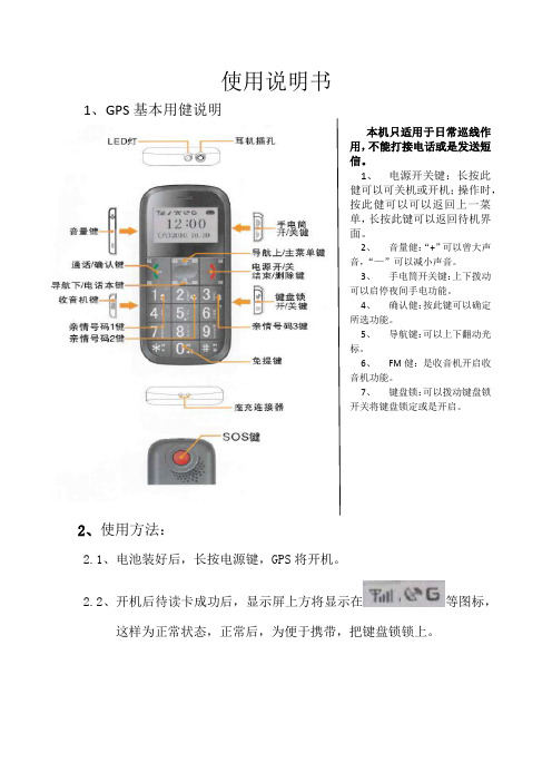
1、GPS基本用健说明
本机只适用于日常巡线作
用,不能打接电话或是发送短
信。
1、电源开关键:长按此
健可以可关机或开机;操作时,
按此健可以可以返回上一菜
单,长按此键可以返回待机界
面。
2、音量健:“+”可以曾大声
音,“—”可以减小声音。
3、手电筒开关键:上下拨动
可以启停夜间手电功能。
4、确认健:按此键可以确定
所选功能。
5、导航键:可以上下翻动光
标。
6、FM健:是收音机开启收
音机功能。
7、键盘锁:可以拨动键盘锁
开关将键盘锁定或是开启。
2、使用方法:
2.1、电池装好后,长按电源键,GPS将开机。
2.2、开机后待读卡成功后,显示屏上方将显示在等图标,
这样为正常状态,正常后,为便于携带,把键盘锁锁上。
2.3、
2.3.1、
2.3.2、
3、注意事项:
3.1、GPS使用过程中,不能进水、烘烤(电池会爆炸)、摔打等。
3.2、GPS要时常保证电池有电状态。
GPS18说明书
(一)功能说明一.主机各部功能位置说明二.主机启动显示说明1.开机启动程序1-1 开机时会先进行荧幕测试,所有字幕会全亮(包括电子罗盘/雷达频率/距离速度显示)。
1-2 会播报欢迎词【欢迎使用全球卫星雷达系统,请系好安全带】。
1-3 坐标版本显示,目前GPS版本ΧΧΧΧ。
1-4 当地时间显示,目前时间ΧΧ:ΧΧ(12小时制)。
1-5 驾驶模式提示,预设值为『安全驾驶限速模式』。
1-6 雷达频率显示当主机接收到雷达讯号时,显示幕会显示收到的雷达频率。
在市区行驶时,当主机收到干扰讯号时,主机也会显示干扰讯号频率雷达频率的种类如下:2.卫星启动状态2-1 当卫星连接成功时,会先播报"祝旅途平安"。
2-2 当机器处于卫星连结状态时,时间中的‘:'会持续闪烁(见图),反之当无法与卫星连接时,时间中的‘:'将不会持续闪烁,在无法与卫星连接的状态时,电子罗盘的东、西、南、北会持续轮流闪烁,当与卫星连接时,电子罗盘会依据车子行进的方向而显示方位。
三.主机功能查询1.系统资讯查询与下载模式▲此功能项目查询需轻按【SET】一秒,方始能进入系统资讯循环查询.如需重复播报,则可轻按【MOD】一秒1-1 经纬度查询,此项目需在机器与卫星连结后,方能查询。
机器会依据目前使用者所在方位播报经纬度与海拔高度,当汽车处于行驶状态也会播报行驶方向。
1-2 日期时间查询,此项目需在机器与卫星连结后,方能查询。
会透过卫星交替显示目前的日期和时间1-3 电瓶电压查询,会依据汽车目前的状况播报电瓶电压数值。
1-4 系统更新模式,当使用者需要更新坐标资料时,需切换GPS主机到系统更新模式。
才能开始进行坐标更新,座标更新网址是 ,在更新之前须注意以下事项:▲系统需求:WINDOWS XP (SP1/SP2 )或WINDOWS VISTA WINDOWS XP (SP1/SP2 )1.DTL USB-to-Serial2.Microsoft Installer3.1 Framework 2.0▲浏览器需求:Microsoft Internet Explorer四.系统功能设定1.系统功能循环设定▲此功能项目查询需长按【SET】三秒,方能进入系统功能循环设定.▲进入系统功能设定后,每按【SET】轻按一秒,就可循环选择设置系统功能,当设置完毕后可长按【SET】三秒储存设定,或静待三秒即回到预设画面。
GPS使用使用说明
eTrex Venture(中文)——奇遇使用手册合众思壮隆重推出中文输入功能完善面积计算器人性化界面第一章序言说明书介绍感谢您购买eTrex Venture(奇遇)GPS接收机——我们不停努力的结果,为了可以使您的新型GPS接收机发挥最大的用途,并且了解所有的操作细节,您可以花些时间阅读一下本手册。
手册由四部分组成:一、序言部分二、速查部分介绍了一些Venture的细节、主要操作页面和基本导航方式三手册部分提供了使用Etrex Venture 的所有细节。
四、附录部分包括一些有关附件,说明书,维修向导,主题索引等方面的信息。
标准配置包括主机1个牵引绳索1根中文说明书1本本手册中,所有的按键将使用黑体字,所有的菜单选项将用“”括起来。
GPS介绍全球定位系统(Global Positioning System - GPS)是美国从本世纪70年代开始研制,历时20年,耗资200亿美元,于1994年全面建成,具有在海、陆、空进行全方位实时三维导航与定位能力的新一代卫星导航与定位系统。
经近10年我国测绘等部门的使用表明,GPS以全天候、高精度、=自动化、高效益等显著特点,赢得广大测绘工作者的信赖,并成功地应用于大地测量、工程测量、航空摄影测量、运载工具导航和管制、地壳运动监测、工程变形监测、资源勘察、地球动力学等多种学科,从而给测绘领域带来一场深刻的技术革命。
随着全球定位系统的不断改进,硬、软件的不断完善,应用领域正在不断地开拓,目前已遍及国民经济各种部门,并开始逐步深入人们的日常生活。
GPS系统的特点:1、全球,全天候工作:能为用户提供连续,实时的三维位置,三维速度和精密时间。
不受天气的影响。
2、定位精度高:单机定位精度优于10米,采用差分定位,精度可达厘米级和毫米级。
3、功能多,应用广:随着人们对GPS认识的加深,GPS不仅在测量,导航,测速,测时等方面得到更广泛的应用,而且其应用领域不断扩大GPS发展历程GPS实施计划共分三个阶段:第一阶段为方案论证和初步设计阶段。
GPS导航系统用户指南说明书
Traveling To Your DestinationSave Current LocationThis option tells the system to store the current location for later use. It does not change or cancel the route instructions you are using at the time to reach a destination.For example, you are following the system's directions to get to a destination. You are sitting at a stoplight and notice a curio shop on the corner. You do not have time to visit it right now, but you would like to in the future. This option saves the location of the intersection so you can select it as a destination at a later date.To save the location (while thevehicle is stopped), touch the vehicle position icon. When the current address is displayed, touch "Save Current Location." After the location is saved, select "Return" to return to the Map screen.The current location is saved in the previous destination list. Use the Previous Destination option in the Main Menu to select it. It will appear in the list as "Save" followed by the location.Navigation SystemTraveling To Your DestinationGPS Signal Strength Green — Strong Yellow — WeakNot shown — No signalNorth Pointer(In 1/20, 1/8, and 1/2 mile map scales, touch tochange map orientation)Time to DestinationMap Scale Adjustment (Appears only when you press Zoom In/Out buttons)Map Scale(Miles per half inch)Blue line — Calculated route White — HospitalYellow — Shopping Mall Orange — University Dark Green — ParkMedium Green — Golf CourseGray — Airport/Stadium/Business Light Blue — Body of WaterCurrent LocationCurrent RoadNavigation SystemMap ScreenDirection to DestinationDistance toDestinationTraveling To Your DestinationLandmark IconsLandmark icons will be shown in the screen if you select the "Show Icon on Map" in the "Set-up Screen". See "System Setup" on page 60.Going Off the RouteIf you leave the calculated route,"Off-route" (manual) or"Recalculating" (automatic) is displayed at the top of the screen.The system will recalculate the route from your current location anddirection to the desired destination;then give you a new route instruction.This recalculation is doneautomatically unless you set it to manual in the Setup Menu. See "System Setup" on page 60.Auto RecalculationIf this option is set to "Automatic"you will see. "Recalculating" flash at the top of the screen for several seconds as the system recalculates the route. This is followed by a new route instruction.Manual RecalculationIf this option is set to "Manual", you will hear a tone when the "Off-route"message is displayed. You mustpress the Joystick or "ReCal" icon in the screen before the system will recalculate your route.Navigation SystemTraveling To Your DestinationModifying the RouteSeveral functions in the system allow you to view the route the system has calculated. You can then have the system recalculate portions of the route. This is helpful if you are aware of road conditions along the calculated route that you wish to avoid.With the map screen displayed, you can push the MAP/GUIDE button at any time to display the guidance screen. With the guidance screen displayed, move the Joystick left or right to see the Direction List. This shows you all the route instructions between your current location and your destination.Instructions that have already been executed cannot be displayed.Push the joystick down to see the upcoming route instructions one at a time. Each push displays the next in-struction in the sequence. Push the joystick up to move backwardthrough the sequence to the current instruction. The display returns to the current route instruction in about 10 seconds if you stop pushing on the joystick.Navigation SystemTraveling To Your DestinationPressing the MENU button with either the map screen or theguidance screen displayed changes the display to:This menu lets you cancel or modify the current calculated route.DetourSelect this option if you encounter an unexpected obstacle, such as a closed road or extremely heavy traffic congestion. The system will calculate a route from your current location that detours you off the original route, and then back onto it after a certain distance.Avoid a StreetThis option lets you delete a street or streets from the current calculated route. This is helpful if you know of road construction or other snags on the prescribed route.Plan New TripSelecting this option cancels the current route and destination. The display returns to the "Main Menu".Back to Current RouteSelecting this option returns you to the original guidance screen.Navigation System。
GPS软件操作说明书
GPS软件操作说明书一:运行GPS软件,双击桌面上的快捷方式图标,然后软件运行后出现二:输入中心注册码和登录密码后:点击确定后,出现下面就GPS软件各个菜单使用说明一下:一:系统管理,系统管理里有六项:1.连接网络:主要是将系统与网络连接起来。
2.断开网络:将网络与系统断开。
3.保存图像:鼠标左键点击保存图像之后,就会出现下图:就是把当前地图截取以BitMap(*.bmp)格式保存在电脑里,例如我把当前的地图截取保存在E:\ 地图截取然后再输入文件名,选择保存就可以了,如下图:下面的图就是刚才截取的2:打印地图,就是把当前地图界面截取,然后以图片形式打印出来,如下图然后选择打印就可以把当前地图打印出来了。
3:注销登录,此功能可以用来切换操作员,以达到优化软件系统选择确定后,出现下面的界面然后再输其它的操作用户和登录密码重新登录,以达到切换操作员和优化软件系统的目的。
4:退出系统,可以关闭软件,以达到退出程序。
选择确定就可以退出系统了二:参数设置参数设置里有八项,如下:1:注册入网资料选择注册入网资料后,出现下面的界面选择新增后出现下面的界面:接下来按照客户入网资料登记相关信息:设备ID总供是6位,每台GPS终端的ID号不一样的。
选择用户安所装GPS设备的型号。
按客户入网登记录如实填写,为客户的车牌号码车载电话,就是车载机里装的中国移动SIM卡的号码点击保存时,显示输入防伪密码(防伪密码在主机ID号下方可见)车辆组别是为了管理车辆而划分的组别,默认是“无分组”。
选择后,出现下图:点击新增出现在车辆组别信息中名称:是输入该辆汽车是哪个公司的负责人:输入该公司负责人姓名联系地址:输入该组别公司的联系详细地址联系电话:输入该组别公司的联系电话。
例如:点击保存后,出现该组别可以对你所选中车辆组别名称的内容进行修改然后再选择保存,就可以保存你所修改的内容。
可以取消对增加资料和修改资料的选择。
可以删除不用的组别名称。
- 1、下载文档前请自行甄别文档内容的完整性,平台不提供额外的编辑、内容补充、找答案等附加服务。
- 2、"仅部分预览"的文档,不可在线预览部分如存在完整性等问题,可反馈申请退款(可完整预览的文档不适用该条件!)。
- 3、如文档侵犯您的权益,请联系客服反馈,我们会尽快为您处理(人工客服工作时间:9:00-18:30)。
GPS自动报站使用说明第一.硬件配置⑴单机板SX-8.8(或一体板SX-150)⑵GPS_V1.0⑶GPS发射天线⑷GPS操作手柄第二.接线配置⑴一体板(SX-150)接J7的位置,背面的丝印为:5V,RX,TX,GND对应GPS_V1.0板J1位置上的:5V,RX,TX,GND单机板(SX-8.8)接J15的位置, 背面的丝印为:5V,SIN,SOUT,GND对应GPS_V1.0板J1位置上的:5V,RX,TX,GND⑵一体板(SX-150)接J5的位置, 背面的丝印为:5V,GND,SR42,SR43,SR44,SR47,对应GPS操作手柄J1位置上的:5V,GND,DAT,CLK,CS,NC单机板(SX-8.8)接J14的位置, 背面的丝印为:5V,GND,SR42,SR43,SR44,SR47,对应GPS操作手柄J1位置上的:5V,GND,DAT,CLK,CS,NC注:其他接线参考通用板规格书第三.文件制作⑴首先是文件的制作,在CF里面新建一个命名为LINExx(xx:01~64)的文件夹,要和客户化设定项一致,下面有专门的说明。
⑵制作片源,片源制作及说明:注意:文件命名(filename)不能用中文,只能用数字+字母命名。
线路表示:目录文件夹“LINExx”,xx(01~64)表示公交线路报站文件制作①广告文件“xxAyy_filename”(如:00A01_FG001)当公交车不在站台范围内,会播放广告文件每个站台间可支持不同的广告文件,“xx”(01~99)表示站台,当”xx=00”表示默认广告文件`,“yy”(01~99)表示广告文件.②上行报站文件“xxBy_filename”(如:01B0_FG002)“xx”(01~99)表示站台,“y”(0-进站,1-出站),当在上行进站区域内播放“xxB0_filename”, 当在上行出站区域内播放“xxB1_filename”.③下行报站文件“xxCy_filename”(如:02C1_FG003)“xx”(01~99)表示站台,“y”(0-进站,1-出站),当在下行进站区域内播放“xxC0_filename”, 当在下行出站区域内播放“xxC1_filename”播放“xxB1_filename”.④礼貌用语文件“xxD_filename”(如:00D_FG004)“xx”(01~04)上图为上行、下行线各6个站台的命名⑤报站配置文件(BUSSET.XML)需要手动制作,打开记事本,制作格式如下所示:<busset><umax="6"><dmax="6"><st="0" u="6" d="6"/><st="1" u="2" d="3"/><st="3" u="2" d="2"/></busset><umax="6">表示上行有6个站<dmax="6">表示下行有6个站<st="0" u="6" d="6"/>表示默认所有站台播放广告文件00A01_filename~00A06_filename注意:u="6" d="6"表示广告文件的个数,根据LINEXX文件夹里面的广告文件的数量来设定文件的个数<st="1" u="2" d="3"/>表示上行第一个站台间播放文件广告文件01A01_filename~1A02_filename,下行第一个站台间播放文件广告文件01A01_filename~01A03_filename<st="3" u="2" d="2"/>表示上行第三个站台间播放文件广告文件03A01_filename~03A02_filename,下行第三个站台间播放文件广告文件03A01_filename~03A02_filename制作完成以后重命名文件为:,注意大写把做好的配置文件和片源放在测码线路文件夹中(即LINExx)第四.GPS测码升级GPS软件,升级前请清空一次EEPROM,(按遥控器上面的:UP,LIFT,RIGHT,DOW,即:上,左,右,下连续两次)升级完成以后手动重启,插如已经做好片源的CF卡,接上GPS天线,装机,请再次检查各个线路的接线,开机测码!测码:按遥控器右键10次,进入测码模式,在测试状态,请停止播放,因为要操作卡,15秒出现经度和纬度!每一次开始第一站为出站:UP ,station:1,out/down,station:1,out进入测码模式后出现:xx.xxx.xxxN,xx.xxx.xxxEUP ,station:1,outGPS catch mode on.出现以上数据说明你已经进入测码模式,(此时需要注意:必须是在出现经度和纬度的情况,才开始跑坐标,坐标出来以后根据实际情况来保存第一站,在测试的时候建议,上公路就开保存第一个坐标)按enter保存上行第一站出站坐标,然后数据会自动跳到下一站:即第二站:up,station:2,in,再按enter保存,以次类方法到最后一站,需要说明的是最后一站为进站:up,station:xx,in按快退键切换到下行;下行也是一样第一站为出站:down,station:1,out到最后一站也为进站:down,station:xx,in然后按停止键保存坐标数据,系统提示重启!确认OK!测码结束!在CF卡的根目录里会自动生成 GPS数据配置文件,然后把这个文件放在对应的测码线路文件夹中(即LINExx)。
如图所示,正常行使状态下,汽车行驶到离站台20~30米按下键采集进站的GPS数据,汽车驶出站台20~30米按下键采集出站的GPS数据。
为了保证采点准确性,采点完成后,需实际运行来验证,按遥控器左键10次,在屏幕的左上方会出现GPS坐标xx.xxx.xxxN,xx.xxx.xxxE,可以和采集的坐标值进行比较修改。
GPS数据配置文件说明:用记事本打开,格式如下:<up><w1="2231" w2="4869" n="0" j1="11355" j2="6280" e="0"> <w1="2231" w2="4704" n="0" j1="11355" j2="6973" e="0"> <w1="2231" w2="4357" n="0" j1="11356" j2="8797" e="0"> ……<down><w1="2231" w2="9300" n="0" j1="11401" j2="3923" e="0"> <w1="2231" w2="8862" n="0" j1="11400" j2="9868" e="0"> <w1="2231" w2="8758" n="0" j1="11400" j2="9457" e="0"> ……<up> : 上行<down> : 下行wX : 纬度坐标jX : 经度坐标n=X: n=0--北 | n=1--南e=X: e=0--东 | e=1--西GPS操作手柄第五.按键定义a)重复_KEY: 重复播报上次内容。
如,上次播报的是“车辆起步,请坐稳扶好,注意安全,下一站…”,按一下此键,重复播报这条语音。
b)01--04_KEY:礼貌用语1—4, 播报设定好的1—4条服务用语。
c)报站_KEY:报当前站点内容,报完站后自动切换到下一站状态。
d)上/ 下行_KEY:切换上行、下行,在数码管上指示第一个发光二极管的相应位为报上行配置好的站点内容;指示第一个发光二极管的相应位为报下行配置好的站点内容。
e)进一站_KEY :当前站台,调后一站。
f)退一站_KEY:当前站台,调前一站。
g)线路_KEY:切换公交线路。
第六.数码管显示数码管显示一共有四位数字显示:第一位数字:表示上行表示下行第二位数字:表示进站表示出站最后两位数字表示站台号,如表示下行04号站台出站本报站系统可以对公交线路64条线路进行随意切换(卡里必须有这么多个文件线路);可以对GPS误差进行距离的调整5M,10M,20M,30M,40M,60M,80M,100M,120M,140M,160M,180,200M(根据站台间距离进行设定)。
如下图所示按遥控器,选中客户化设定项GPS误差项:误差5M~200M距离,站台之间距离比较近,把误差距离调小;站台之间距离比较远,把误差距离调大。
线路项:线路1~64,CF卡里LINE01表示线路1,LINE02表示线路2...LINE64表示线路64,注意设置时,卡里的路线要和设定路线一致。