ATI-PA2模块连接示意图-PG36
300W车载逆变器电路图与原理分析.pptx
SS8550为目前市场上较为常见、易购的三极管,价格也比较便宜,单只售价仅0.3元左右。
KSP44为T。・92形式封装的NPN型三极管。其引脚电极的识别方法是,当面对三极管的印字标识面时,其引 脚1为放射极E、2为基极B、3为集电极C。
KSP44的主要参数指标为:BVCB。=500V,BVCE。=400V,VCE(三)=。.5V,VBE(。N)=。 .75V,ICM=300mA,PCM=。.625W,TJ=150oC,hFE=40~2000
IRF740A为T。∙220形式封装的N沟道增加型MoS快速功率开关管。其引脚电极排序1为栅极G、2为漏极D、3为 源极S。
IRF740A的主要参数指标为:VDSS=400V,ID=I。A,Ptot=120W,RDS(。N)S55。m。
当IRF740A损坏无法买到时,可用封装形式和引脚电极排序完全相同的N沟道增加型M。S开关管IRF740B、 IRF740或IRF730进行代换。IRF740、IRF740B的主要参数与IRF740A完全相同。IRF730的主要参数为 VDSS=400V,ID=5.5A,RDS(。N)31。其中IRF730的参数虽然与IRF740系列的相比略差,但对于150W以下功率的逆 变器来说,其参数指标已经是绰绰有余了。
IGBT模块封装流程 原理图
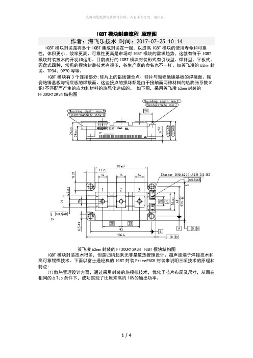
IGBT模块封装流程原理图作者:海飞乐技术时间:2017-07-25 10:14IGBT模块封装是将多个IGBT集成封装在一起,以提高IGBT模块的使用寿命和可靠性,体积更小、效率更高、可靠性更高是市场对IGBT模块的需求趋势,这就有待于IGBT 模块封装技术的开发和运用。
目前流行的IGBT模块封装形式有引线型、焊针型、平板式、圆盘式四种,常见的模块封装技术有很多,各生产商的命名也不一样,如英飞凌的62mm封装、TP34、DP70等等。
IGBT模块有3个连接部分:硅片上的铝线键合点、硅片与陶瓷绝缘基板的焊接面、陶瓷绝缘基板与铜底板的焊接面。
这些接点的损坏都是由于接触面两种材料的热膨胀系数(C 犯)不匹配而产生的应力和材料的热恶化造成的。
如下图,采用英飞凌62mm封装的FF300R12KS4结构图英飞凌62mm封装的FF300R12KS4 IGBT模块结构图IGBT模块封装技术很多,但是归纳起来无非是散热管理设计、超声波端子焊接技术和高可靠锡焊技术。
下面以富士通经典的IGBT封装PrimePACK封装来说明三项技术的原理和特点:(1)散热管理设计方面,通过采用封装的热模拟技术,优化了芯片布局及尺寸,从而在相同的ΔTjc条件下,成功实现了比原来高约10%的输出功率。
使用模拟器的散热管理设计的IGBT模块效果(2)超声波端子焊接技术可将此前使用锡焊方式连接的铜垫与铜键合引线直接焊接在一起(图2)。
该技术与锡焊方式相比,不仅具备高熔点和高强度,而且不存在线性膨胀系数差,可获得较高的可靠性(图3)。
与会者对于采用该技术时不需要特别的准备。
富士公司一直是在普通无尘室内接近真空的环境下制造,这种方法没有太大的问题。
利用超声波直接焊接IGBT模块的铜材料IGBT模块封装技术超声波焊接与锡焊的比较图3:超声波焊接与锡焊的比较(3)高可靠性锡焊技术。
普通Sn-Ag焊接在300个温度周期后强度会降低35%,而Sn-Ag-In及Sn-Sb焊接在相同周期之后强度不会降低。
奥рь安特机电(Oriental Motor)HF-3122操作手册:冷却模块FM系列IP43 55

HF-3122Cooling Module FM SeriesIP43/55 Rated Filter PanelThank you for purchasing an Oriental Motor product.This Operating Manual describes product handling procedures and safety precautions.• Please read it thoroughly to ensure safe operation. • Always keep the manual where it is readily available.Before using the product Only qualified personnel should work with the product.The product described in this manual has been designed and manufactured for use in general industrial machinery, and must not be used for any other purpose. Oriental Motor Co., Ltd. is not responsible for any damage caused through failure to observe this warning.Hazardous substances RoHS (Directive 2002/95/EC 27Jan.2003) compliantChecking the product Upon opening the package, verify that the items listed below are included. Report any missing or damaged items to the branch or sales office from which you purchased the product.• Filter panel........................................1 pc. • Mounting frame................................1 pc. • Mounting screw set...........................2 sets(Tap-tight screws for affixing mounting frame and grille affixing screws) • Operating manual..............................1 copyChecking the model name Check the model number against the number indicated on the product.Location for installation The filter panel is designed and manufactured for installation in equipment. The hood side of the filter panel is designed to IP43 or IP55 to provide protection against ingress of objects and liquids in an environment ofpollution degree 2. Install it in a well-ventilated location that provides easy access for inspection. The location must also satisfy the following conditions: • Inside an enclosure that is installed indoors (provide vent holes) • Operating ambient temperature−45 to +85 °C (−49 to +185 °F) (non-freezing)• Operating ambient humidity 65% or less (non-condensing)• Area that is free of explosive atmosphere or toxic gas (such as sulfuric gas) or liquid• Area not exposed to direct sun• Area free of excessive amount of dust, iron particles or the like • Area not subject to splashing water (rains, water droplets), oil (oil droplets) or other liquids • Area free of excessive salt• Area not subject to continuous vibration or excessive shocks• Area free of excessive electromagnetic noise (from welders, power machinery, etc.)• Area free of radioactive materials, magnetic fields or vacuumInstallation method Install the filter panel onto an appropriate flat metal plate having excellent vibration resistance and heat conductivity. Position the filter panel vertically with the hood outlet facing down.1. Drill a mounting hole in theenclosure.Reference mounting hole dimensions8×Ø3 mm (Ø0.12 in.)L1L2L 1L 2[4×Ø3 mm (Ø0.12 in.) for FMZ23 I-F ]㩷Replacement filter media• IP43 rated filter mediaSet of 5 sheetsModel ApplicableproductFMXAB-D FM series – External dimensions: 209 × 226 mm (8.23 × 8.90 in.)FMXAB-E FM series – External dimensions: 157 × 170 mm (6.18 × 6.69 in.)FMXAB-F FM series – External dimensions: 129 × 134 mm (5.08 × 5.28 in.)• IP55 rated filter mediaSet of 5 sheetsModel ApplicableproductFMXAC-D FM series – External dimensions: 209 × 226 mm (8.23 × 8.90 in.)FMXAC-E FM series – External dimensions: 157 × 170 mm (6.18 × 6.69 in.)FMXAC-F FM series – External dimensions: 129 × 134 mm (5.08 × 5.28 in.)Cooling of the filter media reduces the cooling capacity. Clean or replace thefilter media regularly.• Unauthorized reproduction or copying of all or part of this OperatingManual is prohibited.• Oriental Motor shall not be liable whatsoever for any problems relating toindustrial property rights arising from use of any information, circuit,equipment or device provided or referenced in this manual.• Characteristics, specifications and dimensions are subject to changewithout notice.• While we make every effort to offer accurate information in the manual,we welcome your input. Should you find unclear descriptions, errors oromissions, please contact the nearest office.• is a trademark of Oriental Motor Co., Ltd.is a trademark of Oriental Motor Co., Ltd., and is registered inJapan and other countries.© Copyright ORIENTAL MOTOR CO., LTD. 2006• Please contact your nearest Oriental Motor office for further information.ORIENTAL MOTOR U.S.A. CORP.Technical Support Line Tel:(800)468-3982Available from 7:30 AM to 5:00 PM, P.S.T.E-mail:*****************************ORIENTAL MOTOR (EUROPA) GmbHHeadquarters and Düsseldorf Office Tel:0211-5206700 Fax:0211-52067099Munich Office Tel:08131-59880 Fax:08131-598888Hamburg Office Tel:040-76910443 Fax:040-76910445ORIENTAL MOTOR (UK) LTD. ORIENTAL MOTOR (FRANCE) SARLTel:01256-347090 Fax:01256-347099 Tel:01 47 86 97 50 Fax:01 47 82 45 16ORIENTAL MOTOR ITALIA s.r.l. TAIWAN ORIENTAL MOTOR CO., LTD.Tel:02-93906346 Fax:02-93906348 Tel:(02)8228-0707 Fax:(02)8228-0708SINGAPORE ORIENTAL MOTOR PTE. LTD.Tel:(6745)7344 Fax:(6745)9405ORIENTAL MOTOR (MALAYSIA) SDN. BHD.Tel:(03)79545778 Fax:(03)79541528INA ORIENTAL MOTOR CO., LTD.KOREATel:(032)822-2042~3 Fax:(032)819-8745ORIENTAL MOTOR CO., LTD.Headquarters Tokyo, JapanTel:(03)3835-0684 Fax:(03)3835-1890Printed on Recycled Paper。
CATIA有限元分析

实验报告目录实验一:CATIA 中的工程分析动臂应力分析问题描述解题思路操作过程实验二:电子样机运动机构模拟四连杆运动机构模拟问题描述解题思路操作过程实验三:电子样机空间分析柴油机燃油供给系中输油泵空间分析问题描述解题思路操作过程感想实验一:装载机动臂应力分析问题描述装载机无偏载工作时,动臂承受一定外载荷和来自车架的约束。
动臂结构示意图见图1。
在建立模型时,油缸假设为柔性弹簧,A铰点作为动臂的支点,允许动臂绕通过A 铰点的轴转动,B铰点是动臂油缸支点(动臂油缸的刚度假设为2.0e7N_m)。
C铰点和D铰点是外载荷的作用点。
本实例分析的工况是正铲无偏载,载荷、结构同时对称,最好取出模型的一般,通过施加对称约束,进行有限元求解二、 解题思路1、 进入并载入源文件2、 前处理(施加约束和载荷)3、 求解4、 后处理三、 操作过程1、进入并载入源文件⑴、打开文件 dongbi.CATPART 。
(2) 、进行有限元分析前的基本设置工作。
(3) 、单击 Start/Analysis Simulation/Generative Structural Analysis 进入有限元分析模 块,选择Static Analysis,进入静态有限元分析,如图2所示。
2、前处理El开始EHOVIA V5文件编辑 观图插入工具窗口帮助ITev Analysis Case| [鼻硒定寸/取消Fimt t Element Model - 1 Nodes and Elen ent sStatic Anal]Properties.1Frequency Analysi E]Keep as default starting uielyEi s case图2在A 点建立刚性虚件,如下图所示。
B 点建弹簧虚件,如下图所示u 寿 Properties.1 “事 MateTials. 1 Handler No selectionIT&jri^ Rigid Virtu :al Part. 1 Supports ■■埶 Virtu. … ®限 疋A 占八、、自 由 度如 下 图所 示o圆锥角约束,如下图所示。
绿卡系统终端介绍及与外设连接法3p
处理办法:当营业员以yzzj 登录后,就会出现如图1的画面,国光终端选1,升腾终端和实达终端选择2,如果选择不正确就会出现不能使用功能键的情况。
3、故障现象:保险台席保单输入完毕后提交报“AT控制台外部接口出错,保险系统异常”
处理方法:检查保单输入地址栏,输入地址信息过长或有生僻的字都会报错。
二、UPS后面板图示:
注: 风扇:用于UPS主机降温
输入插座:接市电
输出插座和输出布线插座:接电源板或用电设备
电池接口:接UPS电池柜
第四部分 营业网点常见故障及处理
一、终端及系统常见故障处理
1、故障现象:终端停留在业务画面,按键无反应
处理方法:1、按Ctlr+y 重联机,终端将重新连接主机。
2、如果按Ctlr+y没有反应,检查终端后面的线是否正常连接,如果连接线正常,重启路由器既可解决;如果连接线掉了,重新接上即可。
并口: 接打印机电缆线
键盘口接扫描枪,扫描枪剩下接口接键盘
第二部分 网络设备介绍及连接图示
一、路由器前面板图示:
二、协议转换器图示:
三、路由器后面板图示:
注: 异步口:接网线(连接到哑终端)
局域网口:接网线(连接到网络终端或其它网络设备)
2M接口:接V35线(连接到协议转换器)
AUX口:接专用线(连接MODEM,用于远程拨号)
4.如果之前是用维护菜单的关机功能,需要将电子柜左上方的开关打到ON处ATM即自动进入系统。柜员维护操作面板ຫໍສະໝຸດ 介绍流水纸和凭条纸的安装和拆装
流水打印机装纸:
1)将纸的卷边朝下放入纸槽中,将纸头伸入进纸口,电机会自动将纸张吸出
2)将纸头插入黑色卷纸轴的槽中,绕两圈后再扣上另一头铁片
led驱动电路图及其它知识

TPS92310大功率LED驱动器典型应用电路文章出处:木头东瓜发布时间: 2012-4-1 11:30:08 | 3591 次阅读 | 69次推荐 | 1条留言TI 公司的TPS92310是离线初级侧检测带PFC的控制器,设计用来照明的大功率LED驱动器,采用恒定的导通时间和准谐振开关技术,具有高的功率系数,良好的EMI行能和高的系统效率。
主要用在A19 (E26/27,E14),PAR30/38和GU10型LED灯与固态照明。
本文介绍了TPS92310主要特性,方框图,典型应用电路图,隔离和非隔离拓扑的电路图,以及TPS92310 EVM-8W评估模块主要特性,电路图,材料清单和模块PCB元件布局图。
图1.TPS92310方框图图2.TPS92310典型应用电路图图3.TPS92310隔离拓扑电路图图4.TPS92310非隔离拓扑电路图LED驱动电源电路图LED和其他用电器电源电路一样,如,采用开关电源电路,可以让负载得到质量很好的直流电源,但是电路图,不方便制作,下面给大家介绍一种简易电路,专用于LED驱动电源电路图中,LED驱动电源电路中的元器件也很少,方便制作,元器件参数在电路中,供参考。
LED驱动电源电路图如下:本文介绍一种大功率LED驱动电路模块。
主要用于大功率led灯电路中,可以大功率LED灯电路的驱动问题,采用PAM2803就可以轻松实现驱动问题,先介绍一下PAM2803模块的功能。
PAM2803介绍PAM2803模块是专用于对大功率LED灯电路实现驱动之用。
PAM2803启动电压小,只有0.9V,PAM3803恒流工作电压是1.8~6v,自带过压保护。
封装采用SOT23-6。
最适用于用于电池供电而升压的LED驱动电路中。
PAM2803采用PWM控制方式开DC-DC升压驱动电路。
可以驱动3W大功率LED灯电路,电流可以由外部反馈电路调节,可以在500MA——1A可调,效率可以达到90%。
澳托克IK执行器详细图解之欧阳美创编
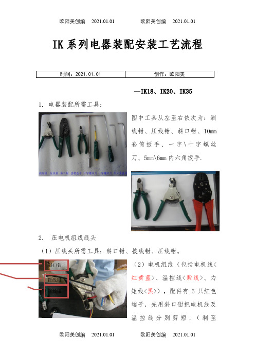
IK系列电器装配安装工艺流程时间:2021.01.01 创作:欧阳美--IK18、IK20、IK351. 电器装配所需工具:图中工具从左至右依次为:剥线钳、压线钳、斜口钳、10mm套筒扳手、一字\十字螺丝刀、5mm\6mm内六角扳手.2. 压电机组线线头(1)压线头所需工具:斜口钳、拨线钳、压线钳。
(2)电机组线(包括电机线<红黄蓝>、温控线<紫线>、力矩线<黑>),配件有5只红色端子,先用斜口钳把电机线及温控线分别剪短,(剩至斜口钳拨线钳压线钳100mm\108mm左右),然后用剥线钳把电机线头剥掉5mm左右,把温控线剥掉10mm左右。
(温控线比较细所以压线时需把线头对折)(3)压端子示意图。
注意事项:压线钳有标识这面必须朝端子口。
压线钳表面红点位置必须朝端子口,压线钳要与端子口平行,手要扶着电机线,防止线头掉出,端子压空,准备好后,将其压下去。
(4)压端子完成后示意图。
2. 安装电机组线将压好端子的电机组线插入箱体的电机孔中。
注意事项:放线时应注意,将U.V.W端由图所见口放入,在放线的同时要注意线的表皮不要被箱体表面的一些毛刺或棱角划破。
3. 安装压力盘(1)所需零件及配件:压力无外露线头,压好后用手拉端子检查是否松动。
导线孔压片按箭头方向将电机线插入盘、压片(金黄色)、黑色护套、黑色弹垫3片、不锈钢垫片3片、外六角螺丝3颗。
外六角螺丝型号IK18 : M6*30mm IK20/IK35: M6*30mm 。
(2)压力盘组合。
组合顺序:压力盘——压片——黑色护套,螺丝顺序:先放垫片——黑色弹垫——螺丝。
注意事项:三种主件都有半圆缺口,都要一一对应。
(3)安装压力盘螺栓所需工具:IK20/35:10mm 套筒。
(4)安装压力盘示意图。
将组合好的压力盘安装到箱体上,半圆缺口需与箱体插线口对齐,组件上的三颗螺丝与箱体转子面上的螺纹孔对齐,并将螺丝拧紧外六角螺丝黑色护套压力盘型号看盘面上的标识注意点:圆口一致。
Rainin SP Pipette Controller 2 操作说明书
O p e r a t i n g I n s t r u c t i o n sR a i n i n S PTable of Contents1. Safety and Regulatory Information 31.1 Important Safety Information 3 1.2 Intended Use 3 1.3 Compatible Liquids 4 1.4 Regulatory Information 42. Introducing the Rainin SP 5 2.1 Overview 5 2.2 Box Contents6 2.3 Rainin SP-compatible Pipettes 73. Setup and Installation 8 3.1 Overview 8 3.2 Battery8 3.2.1 Battery Status Indicator 9 3.2.2 Charging 104. Operation11 4.1 Inserting a Serological Pipette 11 4.2 Adjusting the Speed 12 4.3 Aspirating 13 4.4 Dispensing13 4.5 Checking the Adapter Seal 14 4.6 Replacing the Adapter 15 4.7 Magnetic Hang-up ™16 4.8 Attaching the Support Frame165. Warnings176. Battery Replacement 187. Specifications18 7.1 Operating and Storage Environment 198. Accessories 209. Ordering Information 2010. Care and Maintenance2111. Service 2412. Troubleshooting 2513. Warranty Information 2614. Disposal26R a i n i n S P1. Safety and Regulatory InformationThe following safety information is important for the safe handling and use of the Rainin SP pipette controller. Please read it carefully.Read all safety warnings before using, charging or servicing the Rainin SP.Always use the Rainin SP in accordance with these operating instructions and keep these instructions for future reference. Safety notes are marked with signal words and warning symbols. Ignoring the safety notes may lead to personal injury, damage to the Rainin SP including malfunction, as well as unreliable results.The Rainin SP should only be used in laboratories and production environments by trained specialists who have read these operating instructions. Mettler-Toledo Rainin, LLC is not liable for any damage resulting from misuse, including but not limited to:• Use not in accordance with these operating instructions.• Use with accessories or consumables not recommended by Rainin. • Maintenance or repair by unauthorized personnel. • Unauthorized changes to the instrument.1.1 Important Safety Information1.2 Intended UseRisk of fire and burn.Do not short circuit.Do not disassemble, crush, incinerate or expose to high temperature.R a i n i n S PR a i n i n S PWelcome to Rainin SP pipette controller! This instrument works with all types of 1 mL to 100 mL serological pipettes and can transfer liquid from 0.1 mL to 100 mL.Please read this manual in its entirety before using the instrument. It contains critical usage and technique information that will help you obtain accurate, reproducible results and ensure long-lasting operation.2. Introducing the Rainin SP2.1 OverviewMagnetic Hang-up ™ connection pointBattery status indicatorAspiration/dispense control buttonsSupport frame attachment groovesAspiration cone assemblyCharging portDispense speed controlAspiration speed controlR a i n i n S PIn the Rainin SP box you will find:• 1 Instrument • 1 Magnetic Hang-up • 1 Power adapter • 1 Charging cable • 1 Support frame • 1 Filter• 1 Quick Reference Guide2.2Box ContentsPower adapterSupport frame Charging cable Magetic Hang-upFilterQuick Reference GuideSPR a i n i n SPThe Rainin SP works with any type of standard serological pipette (1 mL, 2 mL, 5 mL, 10 mL, 15 mL, 25 mL, 50 mL and 100 mL).2.3Rainin SP – Compatible Serological PipettesR a i n i n S P• Check to ensure box includes everything.• Check instrument for accessories damage that might have occurred during shipping. • Keep the box and inserts for storage and to return for service (e.g., battery replacement).• Plug the power supply into an electrical outlet using appropriate power plug adapter.• Connect the power supply to the instrument until it locks in place.• The Rainin SP comes with a built-in rechargeable battery.The battery has a two-year life and can only be replaced by an authorized METTLER TOLEDO or Rainin service technician.• After 10 seconds without use, the instrument will enter low-power mode.Pressing any button will reactivate it.• If required, the battery will automatically begin charging when placed onthe magnetic Hang-up ™ or plugged directly into an AC power source.• The battery status display shows the battery's current capacity.3. Setup and Installation3.1 Overview3.2 BatteryR a i n i n S P3.2.1 Battery Status Indicator• When the instrument is picked up, the speed control indicator andbattery status display will illuminate for 10 seconds.• When the speed control button is pressed, the speed control indicatorand the battery status display will illuminate for 10 seconds.• When the aspirate or dispense buttons is pressed, the speed controlindicator and battery status display will illuminate for 10 seconds.• If the speed indicator is not on, press either the aspirate or dispensespeed button and the indicator will display the previously set value.• If the speed indicator light is on, press the speed control button tochange the speed.R a i n i n S PThe battery will fully charge in about three hours and, once charged, will power the instrument for up to 15 hours. Note that after just 10 minutes of charging the battery will provide up to an hour of operation. The battery can be charged by placing the instrument on the magnetic Hang-up if it is connected to a power source, or by plugging the power cord from the AC adapter directly into power outlet on the base of the instrument.Note: The Rainin SP can be used while plugged into a power outlet. Disconnect the power cord from the charger and reconnect it directly into the instrument.3.2.2 ChargingR a i n i n S PThe Rainin SP generates pressure to aspirate or dispense a liquid. It can also dispense using only atmospheric pressure. Aspiration and dispense speeds are controlled by the pressure applied to the respective buttons on the instrument.4. OperationTo insert a pipette, hold the instrument by the head for support, then carefully insert the pipette into the aspiration cone until it is secure and tightly sealed.4.1Inserting a Serological PipetteR a i n i n S PThe aspiration and dispense speeds can be adjusted by pressing the appropriate button.4.2 Adjusting the SpeedDispense speed controlAspiration speedcontrolPressing the button will cycle the speed from low/medium/high, then back to low.To dispense without speed control (gravity), press the dispense speed button until no lights are illuminated.R a i n i n S P4.3 Aspirating123Immerse the tip of the pipette into the liquid.Slowly press the aspirate button. Hold the button in place for continuous aspiration.Touch off the tip of the pipette to the vessel wall before removing it.Liquids can be dispensed at a low speed (flow out) or a high speed (blow out).4.4 DispensingR a i n i n S PLiquids can be dispensed at a low speed (flow out) or a high speed (blow out).4.5 Checking the Adapter Seal1324Insert the pipette into the aspiration cone. Hold the instrument so that the pipette is vertical.Aspirate the maximum volume.Without touching the pipette or pressing the control buttons, observe the tip of the pipettefor approximately 30 seconds.If water leaks from the tube, remove the pipette and carefully disassemble/reassemble the aspiration cone assembly(aspiration cone/pipette adapter/filter module) and check theseal again. If it continues to leak, replace the pipette adapter.R a i n i n SP4.6 Replacing the Adapter142536Remove the aspiration cone by twisting counter clockwise.Insert the filter module into a new pipette adapter.Unplug the filter module pipette adapter assembly from the head of the SP.Reinsert the filter module adapter assembly into the head.Unplug the filter module from the adapter and discard.Replace the aspiration cone by twisting just until snug (do notovertighten).R a i n i n S PThe Rainin SP can be stored using the provided magnetic Hang-up ™. When attached to the power cord, the Hang-up will automatically detect and charge the instrument.• Strong magnets in the base of the Hang-up will hold the hook andSP securely to any ferromagnetic surface (e.g., the steel side wall of a Laminar flow hood).• Place the Hang-up on the metal wall directly where you want it.When removing or repositioning the Hang-up, pull it directly away from the wall to avoid scratching the wall (e.g., avoid sliding the base of the hook along the wall).• Warning: The Magnetic Hang-up has a strong magnetic field.Handle with care.4.7 Magnetic Hang-Up4.8 Attaching the Support FrameThe SP support frame attaches easily. Simply slide the arms of the frame over the grooves one each side of the handle.To remove, gently slide the support frameout of the grooves.R a i n i n S PBecause this instrument may be used to handle hazardous liquids, these operating instructions do not claim to address all of the safety issues associated with its use. It is the user's responsibility to establish appropriate safely and health practices, and determine the applicability of regulatory limitations prior to use.• Every user must read and understand the operating instructions inthis manual.• Follow the general instructions for hazard prevention and safetyregulations (e.g., wear protective clothing, eye protection andgloves).• Observe all specifications provided by reagent manufacturers.• Never use the instrument in an area where there is danger ofexplosion.• Do not use this instrument to pipette flammable liquids.• Only use this instrument to pipette liquids, with strict regard to thedefined limitations of use. If in doubt, contact your METTLER TOLEDO or Rainin sales representative, Rainin Technical Support or the supplier.• Avoid splashes (e.g., over-aspirating).• Only dispense into suitable vessels.• Never use force on the instrument.• Use only original Rainin accessories and spare parts.• Do not alter the instrument or dismantle it any further than asdescribed in these operating instructions.• Always check the instrument for visible damage prior to use. Ifthere is a sign of a potential malfunction, immediately stop using the instrument and consult Section 13, Troubleshooting. Consult Section 13, Troubleshooting. If necessary, contact Rainin Technical Support.• To charge the lithium battery, you must use the power adaptersupplied with the instrument or a replacement adaptor (if original is lost) specified by Rainin.• Protect the power adapter from moisture and do not use it for anyother purpose than recharging the battery in this instrument.• Only METTLER TOLEDO or Rainin service personnel are authorizedto repair or service the instrument.5. WarningsR a i n i n S P6. Battery Replacement /7. SpecificationsThe Rainin SP comes with a built-in rechargeable battery. It has atwo-year life-span and can only be replaced by sending it in for service.Below are the technical specifications for the Rainin SP.6. Battery Replacement7. SpecificationsR a i n i n S P7. Specifications7.1Operating and Storage Environment• The instrument should not be stored with a pipette attached.• Do not expose the instrument to volatile gases over an extended period.R a i n i n S P8. Accessories / 9. Ordering Information8. Accessories9. Ordering InformationR a i n i n SPClean the Rainin SP by wiping the housing with a damp cloth. The housing can also be disinfected using alcohol (ethanol, propanol) or alcohol-based disinfectants.The SP may also be sterilized by applying 30 minutes of ultraviolet irradiation after each experiment. After 600 hours under a 30W UV light the color change should be less than 2.0.Liquid entering the serological pipette adapter/filter module assembly can decrease the instrument's aspiration capacity. If liquid gets in the adapter, you will need to remove and disassemble the aspiration cone assembly. Once the parts have been cleaned and dried, reassemble. If the filter is wet it will need to be replaced.10. Care and Maintenance123Turn the aspiration conecounterclockwise to remove it. Remove the pipette adapter and filter assembly. Remove the filter from the adapter.To disassemble:R a i n i n SP142536Twist the aspiration cone counterclockwise to remove it.Clean and dry the pipette adapter.Pipette adapterFilter moduleUnplug the pipette adapter/filter module from the head of the SP. If there is liquid in the filter module, replace it.Unplug the filter module from the pipette adapter.Plug the filter module into the pipette adapter.To clean and dry the pipette adapter/filter assembly:R a i n i n SP78Plug the filter/pipette adapter assembly into the head of the SP.Twist the aspiration cone clockwise (do not overtighten).The pipette adapter assembly can be replaced, cleaned or autoclaved asdescribed below (121 °C, 1 bar overpressure for 20 min.)R a i n i n S P11. ServiceAny authorized METTLER TOLEDO or Rainin service professional can service the Rainin SP. We cannot accept instruments that are not appropriately cleaned and decontaminated. The Rainin SP may be repaired, but it cannot be calibrated.Go to /contacts to find your local METTLER TOLEDO or Rainin service center.11. ServiceR a i n i n S P12. Troubleshooting12. TroubleshootingTechnical Support Contact Information ChinaPhone: 4008 878 989Email:****************North AmericaPhone: 800 662 7027Email:***********************RoW/contactsR a i n i n S P13. Warranty Information13. Warranty Information / 14. DisposalFor warranty claims, please contact Rainin Technical Service at *************.The warranty is void if the instrument housing has been opened or there is evidence of abuse/misuse. The battery and other parts subject to normal wear and tear (e.g., pipette adapter/filter) are not covered by warranty.The following guidelines should be followed to ensure the proper disposal of the Rainin SP.•Decontaminate the instrument before disposal by following local, regional and national guidelines for biohazardous or radioactive waste disposal.• The lithium ion battery is regulated waste and must be disposed of according to local, regional and national guidelines.•Dispose of the instrument according to local, regional andnational guidelines concerning take-back of electronic equipment and waste.•Recycle original packaging with your local recycling agent.Contact your local METTLER TOLEDO or Rainin representative for more information.14. DisposalMettler-Toledo Rainin, LLC 7500 Edgewater Drive Oakland, California 94621 USA Subject to technical changes/rainin。
- 1、下载文档前请自行甄别文档内容的完整性,平台不提供额外的编辑、内容补充、找答案等附加服务。
- 2、"仅部分预览"的文档,不可在线预览部分如存在完整性等问题,可反馈申请退款(可完整预览的文档不适用该条件!)。
- 3、如文档侵犯您的权益,请联系客服反馈,我们会尽快为您处理(人工客服工作时间:9:00-18:30)。
PA2强电模块电缆连接示意图
1:把PG36电缆防水接头安装在电缆防水接头安装板上(9005-20-1528):
提示:使用金属材质的PG36电缆防水接头;
安装PG36电缆防水接头时不需要红色标记部分;
电缆防水接头安装板的侧面有一个M5内六角螺栓(蓝色标记部分),使用内六角扳手紧固螺栓、固定PG36电缆防水接头。
提示:安装PG36电缆防水接头,推荐红色标记方式、不推荐蓝色标记方式。
2:从工具快换装置本体上卸下PA2模块:
提示:使用内六角扳手从工具快换装置本体上卸下固定PA2模块的2颗M6内六角螺钉(见红色标记部分)。
3:分离PA2模块组件:
提示:使用内六角扳手从PA2模块本体上卸下固定盖板的6颗M6内六角螺钉(见红色标记部分); 仔细阅读模块本体上的提示标签(见蓝色标记部分)。
4:卸下紧固电缆的3个螺母:
提示:注意螺母两面,一面朝外(见蓝色标记部分),一面朝内、有圆弧凹槽设计、与电缆接触(见绿色标记部分)。
5:确定电缆的长度:
提示:整股强电电缆穿过PG36电缆防水接头和安装板;
确定每根电缆在PA2模块内部的长度;
每根电缆剥去19mm的绝缘材料,露出19mm的部分用于与各触点的连接(见红色标记部分)。
6:每根电缆与PA2模块对应的触点连接:
提示:PA2模块A触点接正(+)、B触点接地、C触点接负(-);
固定电缆的螺母有2面,其中的一面有圆弧凹槽,在安装时一定要使用凹槽面与电缆接触(见红色标记部分); 使用10Nm力矩拧紧螺母;
电缆固定后一定要检查是否有零散的电线裸露,避免触点与触点之间接触发生打火事故。
7:恢复PA2模块本体:
提示:PA2模块既可以从左边出线,也可以从右边出线,ATI建议从没有安装模块的面出线;
使用内六角扳手重新固定从PA2模块本体上卸下的6颗M6内六角螺钉(见红色标记部分)。
8:固定PG36电缆防水接头安装板与PA2模块本体的安装:
提示:使用内六角扳手拧紧4颗M6内六角螺钉(见红色标记部分);
拧紧PG36电缆防水接头尾部、固定电缆位置,(见蓝色标记部分)。
9:恢复PA2模块本体与工具快换装置本体的安装:
提示:使用内六角扳手固定PA2模块的2颗M6内六角螺钉(见红色标记部分),需要在螺纹上抹Loctite 242或类似的螺纹胶 ; 推荐PA2模块从没有安装模块的面出线(见蓝色标记部分)。