SIWAREXU_Rev1.0_WT
SIWAREX U 在PCS7 中的使用入门

名称 PCS7 SIWAREX U FOR PCS7 PACKAGE
测试步骤:
版本 V6.1 SP1 7MH4683-3BA64 V4.1SP1
第一、 SIWAREX U 软件包安装,首先安装 SIWAREX U Setup For STEP 7
关键字:
SIWAREX U ,PCS7过程控制系统
Key words:
SIWAREX U,SIMATIC PCS7
SIWAREX U 在 PCS7 V6.1 中的使用入门
测试硬件:
名称 CPU414-4-3 ET200M IM153-2 SIWAREX U-2
测试软件:
订货号 6ES7 414-4XJ04-0AB0
Set to zero Ch.1 Set to zero Ch.2 Send Param. Rcv. Param.
AS FB Parameter QC1LIMV1 QC1LIMV2 QC2LIMV1 QC2LIMV2 QC1_ADJ QC2_ADJ GROSS_C1 GROSS_C2 C1_Z_CMD C2_Z_CMD S_ALL R_ALL
附:SIWATOOL U 应用。 必备条件:RS232 连结电缆,计算机必须有 COM 通讯口。 打开 SIWATOOL U 调试工具,如图。
设定通讯口,在module 下选择connect。
点击“SIWAREX U”,可以设置称重模块的参数。 点击Load cell Channel1,可设置称重传感器的参数。
SUBX_ID 的分配。 RACK_NO 的分配。
SLOT_NO 的分配。 ADDR 的分配。
CFC 程序如下图。
Venus OS开发者文档:GX设备的根用户访问与硬化指南说明书

Venus OS: Root Access1. IntroductionThis document explains how to access a GX device via SSH, or straight on the Serial Console, with the root user. It also covers customizing and hardening a GX device against nonauthorised access.This document is part of the Venus OS developer documentation. The main document is the Venus OS wiki on github.Do note that, while we try to maintain to provide all mentioned functionality in this document, the used commands and functionality may change with future updates.2. Warning about modifying the rootfs1. Your changes can be lost during a firmware updateChanges made to the rootfs will be lost in case of a firmware update. The complete rootfs is overwitten during an update.Of course it is always possible to disable automatic firmware updates. Also there is a data partition (/data), which will be left alone in the image updates, and as such can be used to, upon boot, (re-)install certain changes onto the active rootfs. More details on that below.2. It is possible to brick your GX deviceFor those unfamiliar with the term: Bricking means rendering it useless and unrecoverable. Chances of this are small (depending on what you do), but its certainly possible. And if not fully bricked, then at least in a state from which there is no documentation nor support on how to recover.Note that a solution to this is to do Venus OS experiments on a RaspberryPi rather than a real GX device. The advantage of a raspberrypi is that you can always start from scratch, by re-imaging the sdcard. And the other is that it (the pi) is a low cost device. more information on that.The factory reset procedure, as documented in the normal user manuals of the GX devices, removes everything from the data partition, except for the factory installed files. This will recover from issues caused by problems on the data partition, such as it being full or invalid settings or custom scripts.But it will not recover from all possible mistakes that can be made. Some examples:1.if you accidentally remove files crucial for the boot process, either on the boot partition or the rootfs, then the device won’t boot anymore. The above mentioned factory reset featuredepends on at least certain parts of the system booting up properly. More specifically, itdepends on the linux init process.2.if you remove the files in /data/venus, then -depending on the production date- you might have to restore those manually which might require serial console access. See below. Why does this depend on the production date? Thats because somewhere in 2021 we started writing allfactory data to a different place (an eeprom) to make it more robust.3. Root access3.1 Set access level to SuperuserTo set the root password, first set the access level to Superuser:1.Go to Settings, GeneralSet the Access Level to User and installer, the password is ZZZ2.3.Highlight Access Level (don't open the select page, ie. make sure you are in the General Page, not the Access Level page)4.Press and hold the right button of the center pad until you see the Access Level change toSuperuser. Note: when working from the Remote Console, you need to use the right key on your keyboard. Pressing and holding the right button with your mouse won't work.Now you have access to the super user features.Note that on a touchscreen, such as a Cerbo GX + GX Touch, there is no “right button”. Instead, drag the menu down and hold it down for five seconds. Or, use Remote Console.3.2 Create a temporary root passwordGo to Settings → General → Set root password. And create a temporary root password.Note that, for firmware version v2.00 and later, the root password will be reset by a firmware update. The reason is that the passwd file is on the rootfs, which is fully replaced by an update. More info here.Our advice is to create a complex root password. But use it to login only the first time, and then install a public ssh key(s). Thereafter login with the keys. If key authentication works, you can also safely delete the root password afterwards (passwd –delete root).The password needs to be 6 characters long, minimum.3.3 Enable sshd and log inTo login via ssh, enable SSH on LAN (Settings → General). On Venus versions before v2.40, you need to enable Remote Support, which also enables sshd. More info on Remote Support here.To the login, enter the ip address of the GX device in a ssh client. Most Linux and Mac users will simply do this from the command line:***************.1.23And a very commonly used client for Windows is Putty. For more info, look around on the Internet, there is plenty information available.3.4 Installing ssh keysUsing a ssh key for authentication, instead of a root password, has the advantage that it isn't lost during a firmware update. The keys are stored on the /data partition.First set the root password (once), use that to login, and then copy a public ssh key to~/.ssh/authorized_keys.sshd works with three authorized keys files:~/.ssh/authorized_keys ← you can use this freely~/.ssh/authorized_keys2/usr/share/support-keys/authorized_keysThe third file contains the keys we use for Remote Support login.3.5 Play time! Start executing commandshttps:///live/open_source:ccgx:commandline4. Customizing a GX device4.1 Hooks to install/run own code at bootEverything, except for information on /data, will be wiped after an update.Therefore, the trick to make changes & modifications survive an update, is to put your (patch)files on /data, make them be (re-)installed automatically on startup.If the files /data/rcS.local or /data/rc.local exists, they will be called early (rcS) and late (rc) during startup. These scripts will survive upgrades and can be used by customers to start their own custom software. Implementation details in this commit.Also if venus-data.{tar.gz,tgz,zip} is found on removable storage (usb stick, sd-card) when booting, it will be unpacked into /data. Implementation details in this commit. Added per Venusv2.30~28. Use this to for example make a USB stick that installs the modifications.That venus-data file has one extra feature: if the archive contains rc/* files, it will extract those first. And if there is a file called rc/pre-hook.sh it will run this before unpacking the rest of the archive. Similarly, if there is a file called rc/post-hook.sh, then that file will run this after the unpacking of the archive. For details, read the code in the /etc/rc5.d/S30update-data.sh file.You can test the 'update' with /opt/victronenergy/swupdate-scripts/check-updates.sh -update -force which will install the same version again, but in the other rootfs.For details of the used update mechanism, see here:https:///victronenergy/venus/wiki/swupdate-project4.2 Partitions, read-only rootfs and available disk spaceOn a GX Device, there are three partitions that matter:rootfs partition onerootfs partition twothe data partition4.2.1 One active rootfs at a timeOnly one of the two rootfs partitions will be in use at time. During a firmware update, the newfirmware is installed on the other one; and once finished the subsequent reboot will reboot the device onto that other partition.The data partition is not touched during a firmware update, except maybe some migration scripts that run at boot.4.2.2 Read-only rootfsBy default, the rootfs is mounted read only. Also, by default, it only has 5% of free space.The solution is to run /opt/victronenergy/swupdate-scripts/resize2fs.sh.Further details in the next section.4.2.3 Always prevent running out of diskspaceWhen doing modifications, make sure both the data partition and the rootfs do not run out of space. We don't design or test for that situation.With regards to the size of the data partition, thats easy to check using the df utility. But not so for the rootfs:After logging into a GX device, and checking the free disk space on the rootfs (! that is not the data partition), you might get a bit disappointed at first. Don't worry about that, there will always be only 5% of free space, but thats not the actual free space:The reason for this is that a firmware update replaces the full filesystem on the rootfs, as an image. And its then not by default expanded to the full available space of the partition.To expand it, run /opt/victronenergy/swupdate-scripts/resize2fs.sh. It will expand the filesystem to use all of the available space.Also this remounts that rootfs as read-write.For actual available diskspace on our GX Devices, seehttps:///victronenergy/venus/wiki/machines.To see what resize2fs.sh is doing, without having to log into your Venus OS, see it also here. Note that a firmware update will replace all of the rootfs, as also explained above. Which implies that you'll need to run resize2fs.sh again after doing a firmware update.4.3 Creating a patch fileAs mentioned before, the recommended way of customising Venus OS is by applying patch files. This section describes how to make and apply a patch.You start by making a copy of the original file and modifying it to accommodate your changes. In order to create a patch file containing the changes you’ve made, run the following command:diff -u OriginalFile UpdatedFile > PatchFileIn order to patch the original file with your changes, you can use the below command:patch OriginalFile < PatchFileFor more advanced features please check the manual page of diff and patch.4.4 Adding or modifying servicesChanges made to /service will not survive a reboot. The reason is the/etc/rcS.d/S10overlays.sh script, which copies over the files from/opt/victronenergy/service/* to /run/overlay/service and bind mounts that under/service. So in order to have changes survive a reboot, you need to change the service under/opt/victronenergy/service/* instead of under /service.By default the root filesystem of Venus is read-only. There are three ways to change that: temporally: issue the command mount -o remount,rw / (which holds until the next reboot or issueing mount -o remount,ro /)semi-permanent: issue the command /opt/victronenergy/swupdate-scripts/remount-rw.sh (which holds until the next firmware update)permanent: adding one of the above commands to /data/rc.local (which holdspermanently)5. Hardening a GX device5.1 Limit physical access to the deviceThe first thing to keep in mind is that we as Victron Energy always want an end-user with physical access to the device to be able to gain access to the device again after he has himself accidentally locked out.So the best solution to keep people from tampering with a Venus device is to block physical access tothe device. We do not give specific recommendations regarding that, but a compact server rack with key protection seems to be safe enough in most cases. You can also add an alarm on the digital input of the Cerbo that will ring as soon as the door of the rack opens.People with enough time, knowledge and for example an angle grinder on their hands will always be able to get in. But you will probably be able to tell if people did get access to the device. Also keep in mind that extra physical security will also give extra hassle for the people that are allowed to get the physical access to the device.5.2 Disable touch on the attached screenPer Venus OS version v3.00, we are introducing a feature that allows disabling the touch feature on the GX Touch display.This allows mounting the GX Touch where it is visible by the operators of the system; and at the same time prevent them from using that to elevate their access.Details per GX device:Ekrano GX: a digital input can be configured to be used for this. Wire it to a momentary-push button, that shorts the input (grounds it).Cerbo GX + GX touch: a digital input can be configured to be used for this. Wire it to amomentary-push button, that shorts the input (grounds it).Venus GX: has no screen, not relevant.Color Control GX: will not get this feature.Inside Venus OS, this is handled by the setting /Settings/Gui/TouchEnabled undercom.victronenergy.settings. Which can be scripted with the dbus -y command. See Limiting digital access for an example on how to do that.Note that this setting only disables touch/mouse control. On the remote console you are still able to control the device with keyboard input. That is also true if you plugin an external USB keyboard. With the keyboard it is also possible to toggle the /Settings/Gui/TouchEnabled setting by pressing the Pause/Break key key. So if you need this feature to be switched on, make sure that the USB ports are not accessible.5.3 Limiting digital accessWhen securing the device, it is also advised to disable the Wi-Fi access point, bluetooth and other non-essential services on the device. The below list should be treated as a starting point and can be extended up on:Disable remote touch controlDisable bluetoothDisable Wi-Fi Access pointSet Access level to UserDisable LAN SSHDisable LAN remote console (VNC)Disable Modbus TCPDisable MQTT (via SSL, plaintext and VRM)If you have multiple devices to harden, here is an example of how to automate the process in a scriptable way. Note that we might change those commands, or names and locations of those settings. Therefore, make sure to be careful to check for example the exit code of such script, as well as visually confirm that all works as expected:#!/bin/bashitems="Disable remote touchcontrol;com.victronenergy.settings;/Settings/Gui/TouchEnabled;0Disablebluetooth;com.victronenergy.settings;/Settings/Services/Bluetooth;0Disable Wi-FiAP;com.victronenergy.settings;/Settings/Services/AccessPoint;0Set access level toUser;com.victronenergy.settings;/Settings/System/AccessLevel;0Disable LAN ssh;com.victronenergy.settings;/Settings/System/SSHLocal;0Disable LAN Remote console(VNC);com.victronenergy.settings;/Settings/System/VncLocal;0Disable Modbus TCP;Settings/Services/Modbus;0Disable Modbus TCP (Plaintext);Settings/Services/MqttLocalInsecure;0Disable MQTT on LAN (SSL);Settings/Services/MqttLocal;0Disable MQTT on LAN (Plaintext);Settings/Services/MqttLocalInsecure;0Disable MQTT via VRM;Settings/Services/MqttVrm;0"IFS=''for item in ${items}doIFS=';' read -r description service path value <<< ${item}echo "# ${description}"dbus -y ${service} ${path} SetValue ${value}doneThere are a lot more settings that can be adjusted this way. Easiest is using dbus-spy to check which ones you find interesting. Instead of disabling services, you might want to enable some things too. Just replace the 0 with a 1 to do that.5.4 Installing a tamper alarmBy using the digital input(s) of the GX device, you can set the digital inputs as “Burglar alarm”, which can be used to be alerted on tampering events.Depending on the need, you might want to switch to a silent alarm under General → Audible alarm (service: com.victronenergy.settings, path: /Settings/Alarm/Audible).You can decide whether the input should be treated as an alarm condition, whether the labels should be inverted, and whether the logical levels should be inverted.To swap the labels attached to the alarm, set Inverted to on.If a logical low input (0V) should be considered a positive condition, set Inverted alarm logic to on.5.5 Hardening multiple devicesIf you have a lot of Venus devices to modify, probably the easiest way is to start with using a per-device specific password for the remote console, which only you can can generate. Combining that with a substring from something like /opt/victronenergy/venus-eeprom/eeprom –show serial-number | sha256sum is a fairly secure start.Later replace that by something more strong and store it in your vault. Use the USB stick to put your public ssh keys on the GX device so you can gain remote access.6. Connecting on the serial consoleThe serial console offers a straight connection from your computer. Not relying on TCP or anything else.Its an alternative to connecting to the commandline over ssh.Connecting to the serial console requires a USB interface, ie a USB to serial cable with proper pin-out. For example this one: https:///product/954.The serial consoles on all GX devices are configured to 115200 baud.6.1 Color Control GXAll GX Devices have a dedicated serial console, except for the CCGX. Therefor its documented on a separate page:CCGX Serial Console.6.2 Cerbo GXThe serial console is located on the CPU board, header JP201. GND is pin 1, RX and TX are pins 4 and 5. Here is a picture showing a ADA Fruit Serial Console cable connected to it.Make sure not to connect the red wire.6.3 Venus GXThe serial console is located on the base-board, and can be accessed through the slot between that board and the Ethernet connector on the beaglebone-board.White: TX of the Beaglebone - connect to RX on your cable Black: ground Green: RX of the Beaglebone - connect to TX on your cableMake sure not to connect the red wire.Here is a picture showing how, also using the adafruit serial console cable as referenced above:6.4 GX Card / NanopiThe GX Card is the PCBA inside the MultiPlus-II GX and EasySolar-II GX product ranges. This photo shows the card, when unmounted from these inverter/chargers.Maybe the pins are also accessible without dismantling it, maybe not. Note that all this is at your own risk, as everything on these pages is.The serial console is the pinheader on the right of the photo. In the photo, there is an Adafruit serial console cable connected.6.5 Octo GXThe serial console is located on the base-board, and can be accessed with the top-board unmounted. With the serial console cable connected the top-board can be put back on again.1.Black: groundNC2.3.NC4.Green: RX of the Beaglecore - connect to TX on your cable5.White: TX of the Beaglecore - connect to RX on your cable6.NCMake sure not to connect the red wire.2023-11-06 01:5011/11Venus OS: Root AccessVictron Energy - https:///live/。
SiwareX标定方法

1.将标定电缆按照数字顺序(3Æ3、4Æ4、5Æ5)接入要标定秤的SIWAREX模块,并将另一端与计算机串口相联;2.打开SIWA_U目录中SiwU.exe程序,将会出现SIWAREX U标定画面;3.选择当前秤标定文件“***.SKU”,见下图;4.“Option”Æ “Select Interface”,选择通讯COM口;5.如计算机只有一个COM口,则选择“COM1”,如图所示;6.“Module”Æ“Connect”,选择计算机与模块联结;7.如下图所示:8.如通讯无故障,将会显示如下画面,图中“****”为当前秤上显示读数:9.设定限值:如下图所示,单击“Limit values”小窗口,将会弹出限值设定对话框,单击“Send”(联结时“Send”按纽将显示正常)将已设定好的限值传送到模块,单击“OK”结束;10.开始标定:1)单击小窗口,弹出“Adjustment Data Channel”窗口;2)在如下图所示中,将提供砝码(20/25公斤每个)总重量输入“3”中;3)单击“Send”,将所设定数据传送到模块中;4)“6”为数据显示格式,不需要修改;5)清理秤体内外,保证无外力施加于秤体上,即秤体完全平衡自由的着落在3个称重传感器上;6)标定零点:单击“1”,等待“****”显示值稳定为“0”;如有变化,检查秤体,并重复5);7)标定高点:a)按照“3”数据,将砝码均匀码放在秤体上,并保证秤体完全平衡自由的着落在3个称重传感器上;b)单击“2”,等待“****”显示值稳定为“3”中显示数据;如有变化,检查秤体,重复b);c)依次均匀从秤体上取下100kg砝码,检查“****”显示值是否与实际砝码重量相符,以检查线性是否良好;d)结束标定。
8)如显示线性较差,即显示误差大于0.3%,检查秤体,重复4)、5)、6)步骤。
11.结束标定,保存数据。
称重模块SIWAREX U
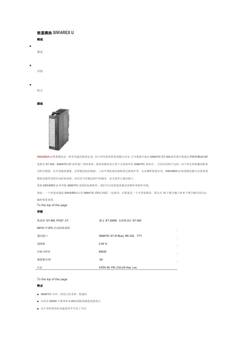
称重模块SIWAREX U概述•描述•详情•特点描述SIWAREX U 称重模块是一种多用途的称重仪表, 用于所有简单称重和测力任务。
它可被集中地在SIMATIC S7-300或非集中地通过PROFIBUS DP连接至S7-400、SIMATIC S7或其他厂商的系统。
紧凑的模块设计易于安装到所有SIMATIC系统中。
它的应用例子包括,用于料仓和料罐的称重式料位测量、吊车的载荷测量、皮带输送机的载荷、工业升降机或轧钢机的过载保护等。
无论哪种称重应用,SIWAREX U称重模块都可以将重量数值直接传送到自动控制系统,没有信号传输过程中的偏差,也无需其它通讯接口。
借助SIWAREX U和其他SIMATIC范围的标准组件,我们可以给您提供最佳的硬件和软件环境。
例如,一个单或双通道SIWAREX U同SIMATIC CPU 312C一起使用,结果就是一个非常划算的、带总共10个数字输入和6个数字输出的自由编程称重系统。
To the top of the page详情通过ET 200M; 直接集成在S7-300集成到S7-400, PCS7, C7,IM151-7 CPU自动控制系统通讯接口SIMATIC S7 (P-Bus), RS 232, TTY故障限0.05 %内部分辨率65535测量数目/秒 50认证ATEX 95, FM, CULUS Haz. Loc.To the top of the page特点■SIMATIC中同一的设计技术和一致通讯■以高至65000分辨率和0.05%的精度测量重量或力■对于双秤使用的双通道型号节省了空间■直接连接一个远程显示器到TTY接口■具有理论校准功能,无需标定砝码■更换模块时,秤无需重新调整秤■借助SIWATOOL的简单参数化■支持危险区域1、2的本质安全称重传感器(可选)■可用于Ex应用中SIWAREX U称重模块:订货号:双通道模块7MH4950-2AA01SIWAREX U有单通道和双通道两种。
西门子SIWAREX称重模块校秤方法

文档来源为:从网络收集整理.word版本可编辑.欢迎下载支持. 西门子SIWAREX称重模块校秤方法
针对近期很多朋友第一次使用SIWAREX称重模块,而且在开始校称的时候遇到一些小问题。
以下就以两种方式进行说明,看如何实现“瞬间”校称。
简单总结为三步走方法SIWATOOL U软件为例
第一步:写校准砝码的重量,50KG为例,两位小数点,按“发送”命令。
就是告诉SIWAREX 称重模块砝码的重量。
界面如下:
第二步:在空秤的时候,点击零点有效。
只需要轻轻按鼠标即可。
界面如下:
第三步:将砝码或实物放入秤上(需要用点力气),然后用鼠标点击“校准重量有效”即可。
界面如下
这台秤就校好了。
为了保存标定数据,点击接收(Receive)即可,等以后换CPU的时候用。
其实大部分时候不需要保存。
CPU坏的几率太低。
如果是通过WinccFlexible来校称的话,就更简单了。
在一个界面下,就可以实现。
以SIWAREX MS为例。
其他称重模块相同。
进入校称界面后:
第一步:写入标定砝码重量。
以100KG为例,默认两位小数点,然后按发送即可。
界面如下
第二步:只需要在空秤的时候,用鼠标轻轻点击“零点有效”Zero valid即可。
界面如下
第三步:将砝码放到秤上,用鼠标轻轻点击“重量1有效”Weight 1 valid 即可。
界面如下
至此,这台秤标定完成。
如果有十几台秤,或更多,优势更加明显。
解决的时间更多。
1。
西门子称重

西门子SIWAREX U电子称重模块在造船龙门吊上的应用作者:杜明吉 武汉港迪电气有限公司供稿单位:西门子称重事业部阅读人次:发布时间:2009-1-21应用领域: 起重机械 门式起重机摘要:本文介绍西门子SIWAREX U电子称重模块在造船龙门吊上的应用,为造船龙门吊起升超负荷限制保Abstract: This paper introduces that the application of shipbuilding gantry crane b关键词:造船龙门吊、称重模块、超负荷限制Key Words: Shipbuilding Gantry Crane, Weighing Module, Overload Limit一 项目简介随着我国现代化建设的发展和世界船舶的需求,近几年来部分世界上的大型造船基地已逐步转移中 武汉港迪电气集团有限公司是集设计、制造、安装、调试起重设备、电气控制系统及高、低压生产图1江苏熔盛重工第一台900T造船龙门吊主机图二 控制系统组成在这龙门吊的上、下小车的两个远程站上各挂一个SIWAREX U模块,上小车远程站上的SIWAREX U模块接1、SIWAREX U模块介绍。
SIWAREX U 称重模块是一种多用途的称重仪表, 用于所有简单称重和测力任务。
紧凑的模块设计易图2 SIWAREX U电子称重模块外形图此模块有两个通道,一个模块可接两个传感器,其特点是:1) 每个传感器与它直接连接时不用经过变送器或放大器转换,因而可减小转换误差,大大提高称重精2) 这种称重模块可以放在远程分站上与PLC相连,因而避免了一般称重系统传感器的毫伏级信号与主机3) 称重模块内面电路集成度高,并有独立的CPU系统,因而稳定性好,占用CPU的资源不大,对温度、气4) 模块称重标定简单,用PC机与模块RS-232通讯,标定一次成功,不用常规多次标定取平均值,去皮5) 该称重模块还可直接接数字显示仪表,就地显示称重值(本机未用此功能)。
SIWAREX WP231工程说明书
Automated Precision WeighingSIWAREX WP231E n g i n e e r i n g N o t ePBK9/PFK9-APW Weigh Platformswith SIWAREX WP2312E n g i n e e r i n g N o t eInhaltsverzeichnis1.1 Field of application ....................................................................................... 32.1 Connecting to Siwarex WP231 ...................................................................... 4 2.2 Configuring Siwarex WP231 ......................................................................... 5 2.3Configuring PBK9/PFK9 Weigh Platform ......................................................... 5 2.3.1 Connecting the weighing sensor to a PC ................................................................... 5 2.3.2 RS422/485 interface .............................................................................................. 5 2.3.3 Weight output ........................................................................................................ 6 2.3.4 User mode ............................................................................................................ 6 2.4 Weight transmission with Siwatool ................................................................. 6 4.1 Other Applicable Documents .......................................................................... 8 4.2 Figures . (8)1Introduction1.1Field of applicationPBK9/PFK9-APW weigh platforms from METTLER TOLEDO (hereafter referred to as “weighing sen-sors”)were developed especially for operation in automated plants. The weighing sensors profides an optionfor direct connection to the SIWAREX WP231 weighing system by Siemens (hereafter referred to as "Si-warex"). This document describes the steps for commissioning and optimizing this kind of connection.Figure 1: Connection to Siwarex via RS48534E n g i n e e r i n g N o t e2 CommissioningThis chapter summarizes, in form of a list, the steps required for commissioning PBK9/PFK9-APW weigh platforms at Siwarex.2.1 Connecting to Siwarex WP231The following diagram shows the connection of the PBK9/PFK9-APW weigh platforms to Siwarex WP231.Figure 2: Connection diagrammAssignment of the connections at SIWAREX WP231for the connection with PBK9/PFK9-APW weigh plat-form:2.2Configuring Siwarex WP231The following sections describe the steps required to configure the Siwarex when using Siwatool PCSoftware. Service mode must be activated before the records can be sent from Siwatool to the Siwarex:service commands-> Service Mode ON. When the service mode is activated, the corresponding icon(open-end wrench on red background) appears in the status bar.For SIWAREX WP231 as of firmware V3.0.4, parameters in the data record 3 and 13 must be adjustedas follows:DR3:Weight unit: grLoading cell type: Digital load cell Mettler Toledo PBKMaximum weight: capacity of the weighing sensor (unit: gr)Calibration weight 0: 0Calibration weight 1: capacity of the weighing sensor (unit: gr)Calibration weight 2: 0Calibration digits 0 (measured): 0Calibration digits 1 (measured): (capacity of the weighing sensor (unit: gr)) / (resolution)e.g.: 1 kg / 0.1 g = 1000 gr / 0.1 gr = 10,000Calibration digits 2 (measured): 0DR13:RS485 Protocol: Mettler Toledo PBK/PFK9 (Code 4)RS485 Baudrate: 38400RS485 Parity: evenRS485 Data Bits: 7RS485 Stop Bits: 1Delay: 2000 ms2.3Configuring PBK9/PFK9 Weigh PlatformThe steps are described below to configure the weighing sensor such that it operates with Siwarex.2.3.1Connecting the weighing sensor to a PCThe RS232 interface of the weighing sensor should be connected to a PC (using APW-Link TM - Free Con-figuration Tool – /apw-link) via the SubD9 connector of the ConBlock. The interface pa-rameters are configured in factory settings as follows: 9,600 baud, 8 data bits, no parity and1 stop bit.These settings shall NOT be modified.2.3.2RS422/485 interfaceFor the weighing platform, following parameters need to be configured:Parameter Value DescriptionM103 1 2 Configure the communication interface of the weighing platform as "RS485mode (half-duplex)"COM 1 8 0 0 Configure the communication interface of the weighing platform as follows:▪38400 bits per second▪7 data bits / even parity / 1 stop bit▪No handshakeM68 0 Keep the parameters of the communication interface permanently stored,such that they are not reset to factory defaults after a power cycle56E n g i n e e r i n g N o t e2.3.3 Weight outputFor seamless communication with the Siwarex, the update rate must be configured as follows:Update rate (UPD): UPD 922.3.4 User modeThe weighing sensors are automatically set to zero at power on. This might be undesirable in certain applications, particularly for larger platforms when a weight value shall be recovered after power off. When selecting the mode described below, the weight values refer to a fix reference point (as per pro-duction setting) and the zeroing at start up is disabled.Start-up with fix reference point: M35 12.4 Weight transmission with SiwatoolAfter successfully configuring the Siwarex and the weighing sensor, Siwatool can be used to weigh forcontrol purposes.The "Start Send" command (code 905) is used to send the individual records to the Siwarex. To con-firm, a record with “Receive” can be read out from the Siwarex. The communication can be stopped with the "Stop Send" command (code 906).Below in the picture, you can see the overview of the SIWATOOL:Figure 3: Siwatool(1) Control elements for SIWATOOL and the for the operation of the weighing sensor (2) Parameter list of the SIWATOOL module (3) Offline values of the SIWATOOL module(4) Online values of the connected SIWAREX module3Supported METTLER TOLEDO ProductsFTAV9.5.2WMS/WMSPBK9-APW/PBK9PFK9-APW/PFK9SLF6/SLF67Mettler-Toledo GmbH IndustrialCH-8606 Nänikon, SwitzerlandSubject to technical changes© 03/2017 Mettler-Toledo GmbHPrinted in Switzerland EN181_160407 4 Appendix4.1 Other Applicable Documents[1] METTLER TOLEDO, Reference Manual, Standard Interface Command Set (11781363G)[2] METTLER TOLEDO, Installation Manual PBK9 bench scales (30233012A)[3] METTLER TOLEDO, Installation Manual PFK9 floor scales (30233015A)[4]Siemens, Siwarex WP231, Device Manual, version 06/2014 (or later)4.2 FiguresFigure 1: Connection to Siwarex via RS485.................................. 3 Figure 2: Connection diagramm .................................................. 4 Figure 3: Siwatool (6)。
SIWAREX FTA_SIMATIC_处理指南说明书

©Siemens AG 1Using SIWAREX FTA within STEP7Quick GuideFor modules with order number 7MH4900-2AA01Contents1 2 3 4 5Introduction ……………………...………………………………….………….. Organisation of the memories …………………………………………… …. Communication concept ………….............................................................. Order to SIWAREX FTA ………….………………...………………..……... Reading and writing data’s …………….…………… ………………………..2 3 4 5 7IntroductionSIWAREX FTA is a calibratable and versatile weighing electronics for SIMATIC S7, C7 and PCS7. It can be used for automatic and non-automatic weighing, e.g. for the production of mixtures, filling, loading, monitoring and bagging.Purpose of this document for functional safetyThis programming manual contains important information that you will require to commission and use the device.It is aimed at persons who install the device mechanically, connect it electrically, parameterize and commission it, as well as at service and maintenance engineers.Notes on warrantyThe contents of this programming manual shall not become part of or modify any prior or existing agreement, commitment or legal relationship. All obligations on the part of Siemens AG are contained in the respective sales contract, which also contains the complete and solely applicable warranty conditions. Any statements on the device versions described in the programming manual do not create new warranties or modify the existing warranty.The content reflects the technical status at the time of printing. We reserve the right to make technical changes in the course of further development.Validation of this documentThis documentation is only valid in conjunction with the manual SIWAREX FTA.©Siemens AG 22 Organisation of the memoriesSince SIWAREX is working autonomous with a microprocessor, it has its own memory. A memory inside the PLC communicates with a memory of same structure inside SIWAREX module.All parameters of this memory are split into data records (DR). The data records are organised according to process steps (tasks) that you have to perform during the commissioning phase or during the process itself.Parameterisation of the SIWAREX module is done by writing data’s into its memory, Information’s about the process is done by reading data’s and order are given to SIWAREX by transferring specific data’s to the FTA.Data Record communication reduces the quantity of data's transferred to the minimum©Siemens AG 3©Siemens AG 43 Communication conceptThe next picture explains how the orders and the data’s are transferred to SIWAREX FTA.To read data’s, the user program gives a command code to the FB SIWA_FTA, the command for example “read data record 30” has a specific number in this case 230. Receiving this orderSIWAREX FTA sends the DR30 to FB-SIWA_FTA, who transfers the DR30 into the appropriate location of DB-Scale.To write data’s the user program write first those data’s into DB_Scale. Then, the user program gives a command code to the FB SIWA_FTA, the command for example “write data record 22” has a specific number in this case 422. FB SIWA_FTA read the DR22 from the appropriate location of DB-Scale and sends it to SIWAREX FTA.The next screenshot shows the contain of the STEP7 project.4 Giving an order to SIWAREX FTAFirst you need to know which commands exist. A list of all orders is to be found in the chapter 6 of the manual:A command is send thru defined data’s inside the data block DB_Scale.The function block FC Execute_Command. Manage a group of three commands, CMD1, CMD2 and CMD3. Those are foreseen to transfer orders to SIWAREX. CMD3 is used for OB35, CMD2 is used for the HMI panel and CMD1 is usually used by the STEP program. The three command blocks are to be found in the DB_Scale at address DBW40 toDBW50.The background task of OB35 refresh, every 100ms, the DR30, 31, 34, 35 and the ASCII weight with crypto data’s for legal for trade applications are also updated.©Siemens AG 5To send a command enter the command code at the address DBW40 as an integer.Then trigger the command by setting the bit s_CMD1.bo.CMD1_Trigger to “1” This bit has to be set with an edge to avoid double triggering of the command. The bit is automatically resetted to “0”.Bit s.CMD1.bo.InProgress indicates that the command is running, this can go for several OB1 cycles.Bit s.CMD1.bo.FinishedOK indicates that the command was successfully terminated.Bit s.CMD1.bo.FinishedError indicates for 1 cycle that the command was not completed. The code of the error is given in DB_Scale Byte 9 “b_CMD_Err_CODE”The number that is output is decoded in the table “Data and Operating Errors” in chapter 7.6.The value remains in the output until the next command is triggered. The evaluation is to be performed when the bit CMD_ERR:= “DB_SCALE”.bo_CMD_ERR is set.©Siemens AG 65 Reading and writing Data’sThe data records described in Chapter 5 of the manual and also in SIWATOOL (see PDF-File SIWAREX_FTA_Quick Guide_SIWATOOL) may be read or written.Always a complete Data Record can be transferred in one or another way.The order number to read a Data Record is “2xx” where xx is the DR-Number.For example read “Data Record 30” which contains weight and state of the scale is done with command “230”.Here an example of programming.The order number to write a Data Record to SIWAREX is “4xx” where xx is the DR-Number.For example to define the dosing setpoint you need to write first the value of the setpoint into DR20 this is address DB_Scale.DBD526. Then send the command “420” (Write DR20).DB72.DBX 31.4 is the trigger to write the setpoint coming from the S7 program.©Siemens AG7If you have any issues or suggestions regarding the related products or documents, please feel free to contact:Technical support for SIWAREX:Siemens AGIndustry Automation (IA)Sensors and CommunicationProcess InstrumentationD-76181 KarlsruheGermanyTel: +49 721 595 2811Fax: +49 721 595 2901E-mail: *******************************Website: /siwarex©Siemens AG8。
- 1、下载文档前请自行甄别文档内容的完整性,平台不提供额外的编辑、内容补充、找答案等附加服务。
- 2、"仅部分预览"的文档,不可在线预览部分如存在完整性等问题,可反馈申请退款(可完整预览的文档不适用该条件!)。
- 3、如文档侵犯您的权益,请联系客服反馈,我们会尽快为您处理(人工客服工作时间:9:00-18:30)。
SIWAREX U选型目录列表:
1. SIWAREX U单通道称重模块(接一台秤)
用于S7-300CPU或通过ET200M集成在S7-400(H),PCS7(H),C7和第三方厂家的控制系统。
有条件的通过IM153-1独立运行
订货号:7MH4950-1AA01 (完全替代7MH4601-1AA01)
图片信息
2. SIWAREX U双通道称重模块(可接两台秤)
用于S7-300CPU或通过ET200M集成在S7-400(H),PCS7(H),C7和第三方厂家的控制系统。
有条件的通过IM153-1独立运行
订货号:7MH4950-2AA01 (完全替代7MH4601-1BA01)
3. SIWAREX U组态软件包,针对SIMATIC S7 版本V5.4或更高版本
包含:SIWATOOL U调试软件,例子程序,SIWAREX U英文手册,集成于STEP 7的硬件组态包。
订货号: 7MH4950-1AK01 (完全替代7MH4683-3AA63)
4. SIWAREX U组态软件包,针对PCS 7 V6.X版本
订货号:7MH4683-3BA64
图片信息:
5. SIWATOOL软件通讯编程电缆
一端是9针接口,连接电脑的COM口RS232,另一端是三根接线端子,连接于SIWAREX U上。
3米长。
同时可用于SIWAREX CS模块
订货号:7MH4607-8CA
图片信息:
安装材料附件
1. 20针前连接器,带螺钉的接线端子。
每个SIWAREX U模块均需要一个,否则无法
接线。
订货号:6ES7392-1AJ00-0AA0
图片信息:
2. 屏蔽连接元件,可供两个SIWAREX U使用
订货号:6ES7390-5AA00-0AA0
图片信息:
3. 屏蔽连接端子,每包两个,适合线径为4到13mm的。
适合传感器电缆,RS485和
RS232接口。
订货号:6ES7390-5CA00-0AA0
图片信息:
4. S7安装导轨,用于安装SIWAREX模块或CPU等S7模块。
根据不同长度,有不同
订货号
订货号:6ES7390-1AB60-0AA0 160mm
6ES7390-1AB60-0AA0 160mm
6ES7390-1AE80-0AA0 480mm
6ES7390-1AF30-0AA0 530mm
6ES7390-1AJ30-0AA0 830mm
6ES7390-1BC00-0AA0 2000mm
图片信息;
其他可能用的附件
1. PS307电源,24伏直流电源,输入220VAC,输出24伏,根据电流输出大小,分
几个型号
订货号: 6ES7307-1BA00-0AA0 输出2A
6ES7307-1EA00-0AA0 输出5A
6ES7307-1KA00-0AA0 输出10A
图片信息:
2. 标签条,每包10个,备件
订货号:6ES7392-2XX00-0AA0
2. SIWAREX JB接线盒,铝制的。
可以同时连接4个传感器
订货号: 7MH4710-1BA
图片信息:
3. SIWAREX JB接线盒,不锈钢材质,可同时连接4个传感器
订货号: 7MH4710-1EA
图片信息:
4. EX防爆接口,SIWAREX Pi用于连接本质安全的传感器。
没有ATEX认证订货号: 7MH4710-5AA
图片信息:
5. EX防爆接口英文手册SIWAREX Pi
订货号; C71000-T5974-C29
6. SIWAREX IS EX接口。
有ATEX认证,没有UL,FM认证。
订货号: 7MH4710-5BA (短路电流少于199mA DC)
7MH4710-5CA (短路电流少于137mA DC)
图片信息:
电缆信息
1. 橙色外皮电缆,线径是Li2Y 1*2*0.75 ST + 2*(2*0.34ST)-CY,外径10.8mm
订货号:7MH4702-8AG
图片信息:
2. 2. 蓝色外皮电缆,线径是Li2Y 1*2*0.75 ST + 2*(2*0.34ST)-CY,外径10.8mm。
用在防爆场合,PVC绝缘材质。
订货号:7MH4702-8AF
3. TTY通讯电缆,用于连接远程显示。
订货号: 7MH4407-8BD0
-------------------------------------------------------------------------------------------------------- SIWAREX U 应用实例
SIWAREX U称重模块相关手册下载连接:
/CN/view/zh/10807025/133300
SIWAREX U一览:
可与SIMATIC S7/M7/PCS 7集成
通过ET 200M与PROFIBUS-DP连接
通过SIMATIC获得全部数据
通过SIMATIC获得全部数据(可选1个或2个通道)
精度:0.05%,内分辨可达65000
两个接口,用于远程显示器和PC连接
通过WINDOWS简便的确定参数
理论上标定无需标定称重
清零功能,可定义极限和可编程的数字式过滤器
与SIWAREX IS联合的本安称重传感器,用于危险区域1,2(可选)
不必重新校正配料的情况下更换模块
如果您对相关产品或此文档有任何技术问题或建议,可直接联系:
西门子(中国)有限公司
自动化与驱动集团技术支持与服务热线
电话: +86 400-810-4288
传真: +86 10 64719991
邮箱: @
网址:
自动化与驱动集团传感器与通讯部门称重事业部
电话:+86-21-38892381
传真:+86-21-38893264。