水流开关使用说明书 doc
安恒电子流动水平开关产品说明书
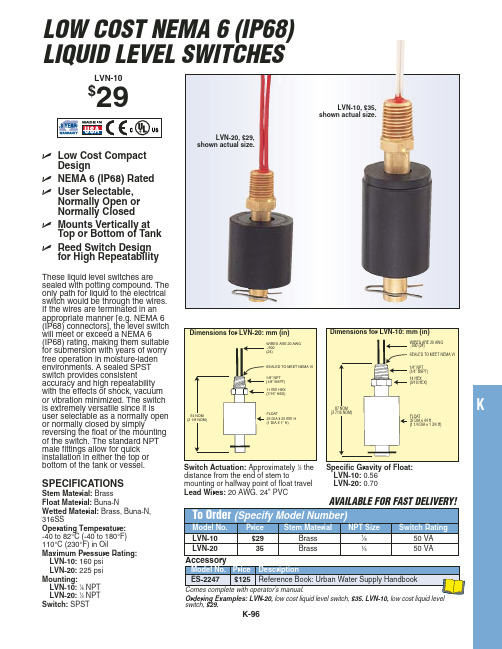
ߜ Reed Switch Design for High Repeatability
LVN-20, $29, shown actual size.
These liquid level switches are
sealed with potting compound. The
only path for liquid to the electrical
switch would be through the wires.
If the wires are terminated in an
appropriate manner [e.g. NEMA 6
(IP68) connectors], the level switch will meet or exceed a NEMA 6
LVN-10: 1⁄8 NPT LVN-20: 1⁄4 NPT Switch: SPST
Comes complete with operator’s manual.
Ordering Examples: LVN-20, low cost liquid level switch, $35. LVN-10, low cost liquid level switch, $29.
54 NOM (2 1/8 NOM)
SEALED TO MEET NEMA VI
1/8" NPT (1/8" BSPT) 11 mm HEX (7/16" HEX)
FLOAT 25 DIA x 25 mm H (1 DIA x 1" H)
87 NOM (3 7/16 NOM)
水流计使用方法说明书
水流计使用方法说明书使用方法说明书一、产品说明本说明书主要介绍水流计的使用方法。
水流计是一种用来检测流体流量的仪器,适用于各种液体和气体的流量测量。
本水流计采用先进的技术和高精度传感器,能够准确、稳定地测量流体的流量。
二、使用前准备1.确认产品完整:在开始使用前,检查水流计是否完好无损,并确保配件齐全。
2.仔细阅读说明书:请认真阅读本使用方法说明书,了解产品的结构、性能和使用要求。
3.检查流体参数:在使用水流计时,需要了解被测流体的温度、压力和介质等参数,确保测量的准确性和安全性。
三、使用步骤以下是水流计的使用步骤:步骤一:安装与接线1.选择合适的安装位置:根据实际需要,选择合适的安装位置并固定水流计。
2.连接电源:将水流计的电源接线与电源线连接,确保电源供应稳定。
3.接线:将水流计的信号接线与检测设备接线端口连接,确保信号传输畅通。
步骤二:参数设置1.打开电源:接通电源并确认电源指示灯亮起。
2.进入设置界面:根据产品说明书,进入相应的设置界面。
3.设置参数:根据被测流体的实际参数,按照说明书中的指导进行参数的设置。
步骤三:校准1.开始校准:在校准前,请确保水流计已经预热并稳定工作。
2.按照校准操作说明:根据产品说明书中的校准操作说明,按照要求进行校准。
3.保存校准数据:根据说明书中的指引,将校准数据保存在水流计中。
步骤四:开始测量1.打开水流计:根据产品说明书中的指引,打开水流计并等待其初始化完成。
2.选择测量模式:根据需要选择合适的测量模式,并调整相应参数。
3.开始测量:按下开始按钮,水流计将开始测量流体的流量。
4.记录数据:在测量过程中,可以查看实时数据,并记录需要的数据。
步骤五:维护与保养1.定期清洁:根据产品说明书,定期清洁水流计,确保其正常工作。
2.保护仪器:使用水流计时,请避免剧烈震动和碰撞,保护仪器免受外界损伤。
3.定期维护:按照产品说明书中的要求,定期对水流计进行维护和保养。
四、注意事项1.安全使用:使用水流计时,请遵守相关安全操作规程,确保人员和设备的安全。
水流开关水流量开关安全操作及保养规程
水流开关水流量开关安全操作及保养规程1. 前言水流开关水流量开关是用于监测水流状态并控制水流量的装置。
本文将介绍水流开关水流量开关的安全操作规程以及保养规程,帮助用户正确和有效地使用和维护该装置。
2. 安全操作规程2.1 安装前的准备在安装水流开关水流量开关之前,需要进行以下准备工作:•确保安装位置符合设备要求,并能够方便监测水流状态;•检查设备包装是否完好,确保设备没有损坏;•确保安装人员具备相关的安装经验和技能。
2.2 安装步骤按照以下步骤进行水流开关水流量开关的安装:1.关闭水源,确保工作环境安全;2.清洁安装位置,确保没有杂物和污垢;3.将水流开关水流量开关安装在合适的位置,使用螺丝固定;4.确保装置与水管连接紧密并且无泄漏;5.打开水源,检查设备是否正常工作。
2.3 操作注意事项•使用前请仔细阅读产品说明书,并按照操作步骤进行操作;•请勿在高压下操作该装置,以免发生危险;•请勿将棉布等可燃物放置在装置附近,以免发生火灾;•请勿使用尖锐物体损坏装置,以免影响正常使用。
3. 保养规程正确保养水流开关水流量开关可以延长其使用寿命,并确保其性能正常。
以下是一些常见的保养规程:1.定期清洁:定期清洁装置以去除污垢和杂物。
首先,关闭水源,将装置拆卸下来,用清水和中性清洁剂清洁各个部位,然后用干净的布擦干并重新安装。
2.注意防冻:在寒冷的冬季,如遇到结冰的情况,请关闭水源并将装置从水管中拆卸下来,放置在温暖干燥的地方,等待冰融化后再重新安装。
3.定期检查:定期检查装置的工作状态,确保其正常运行。
特别注意观察是否有泄漏现象,如有泄漏及时处理。
4. 总结水流开关水流量开关是一项重要的设备,用于监测水流状态并控制水流量。
正确的操作和保养可以确保该装置的正常性能和安全使用。
本文介绍了水流开关水流量开关的安全操作规程以及保养规程,希望能对您有所帮助。
注意:本文仅用于提供操作和保养的参考信息,具体操作和保养应根据设备使用说明书进行。
FSW300系列流量开关说明书
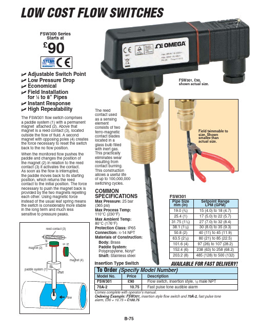
FSW300 Series Starts at
£90
Adjustable Switch Point
Low Pressure Drop
Economical
Field Installation for 1⁄2 to 8" Pipes
Instant Response
Dimensions (Excluding Paddle or Tee): 114 x 38 x 89 mm (4.5 x 1.5 x 3.5")
SPECIFICATIONS FSW302, 303, 304
Max Pressure: 25 bar (362 psi)
Max Process Temp: 110°C (230°F)
4.9 to 6.8 (1.3 to 1.8) 9.5 to 12.1 (2.5 to 3.2) 10.6 to 14.8 (2.8 to 3.9)
Comes complete with operator’s manual. Ordering Example: FSW305-G, inline flow switch, 1⁄2" PVC tee connection, 70A-2, audible alarm, £90 + 10.75 = £100.75
Comes complete with operator's manual.
Ordering Example: FSW301, insertion style flow switch and 70A-2, fast pulse tone alarm, £90 + 10.75 = £100.75
B-75
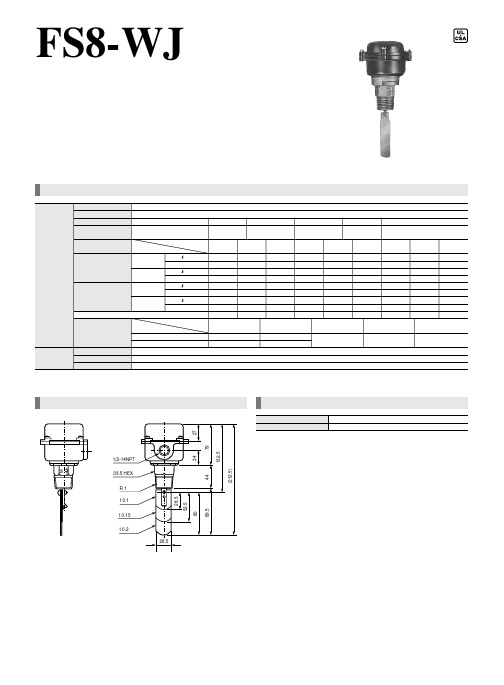
FS8-WJ 防溅型流量开关 说明书
重量 约 0.9Kg 2 55 0.39 35 0.27 210 1.6 180 1.36 对应2B 2 1/2 70 0.36 45 0.24 270 1.44 220 1.19 57mm 115VDC 0.3A
颜色 黑色 3 95 0.31 65 0.21 330 1.16 270 0.95 对应3B
最大使用压力 1.03MPa 11 20 0.55 15 0.37 65 2.0 55 1.7 对应1B 115VAC 7.4A 44.4A 1 14 / 30 0.48 20 0.34 110 1.9 90 1.6 32mm
温度范围 0~107℃ 1/2 35 0.45 25 0.31 140 1.8 120 1.5 38mm 230VAC 3.7A 22.2A
FS8-WJ
防溅型流量开关
FS8-WJ防溅型流量开关是一插入型的流量开关,安装于1~6(B) 英寸的水流管道上,用于探测水的断流或低流量。 其传感部分由一挡板和一内藏微动开关小箱组成,挡板连接一个 微动开关,当流量变化时,挡板带动微动开关动作,其动作流量 可以通过一个流速调整螺丝调整。
规格书
本体/ 操作单元 适用流体 输出信号 型号 FS4-WJ 动作流量 最小调整值 (出厂设定) 水 (无腐蚀性) ON-OFF (微动开关SPDT 接点) 接液部材质 本体:青铜 挡板:蒙乃雨 管道尺寸(B) 流量 动作 停止 最大调整值 动作 停止 插入挡板尺寸 接点容量 /min m/s /min m/s /min m/s /
型号 FS8-WJ 说明 防溅型流量开关, NEMA-4X (IP56)
27 79 1/2-14NPT
M
132.5 89.5 (212.5) 44
33.5 HEX R1 t 0.1 t 0.15 t 0.2 28.5 28.5
IO-Link数字流量开关操作手册说明书

Before UseDigital Flow SwitchPF3A703H/PF3A706H/PF3A712H-LSafety InstructionsThese safety instructions are intended to prevent hazardous situations and/orequipment damage.These instructions indicate the level of potential hazard with the labels of"Caution", "Warning" or "Danger". They are all important notes for safety and mustbe followed in addition to International standards (ISO/IEC) and other safetyregulations.OperatorThank you for purchasing an SMC PF3A703H/PF3A706H/PF3A712H-L DigitalFlow Switch.Please read this manual carefully before operating the product and make sure youunderstand its capabilities and limitations. Please keep this manual handy forfuture reference.Safety Instructions1324DisplayBody(IN side)Connector pin numbers(on the product)Mounting•Never mount the product in a place that will be used as a mechanical support during piping.•Never mount the product upside down.•Attach the piping so that the fluid flows in the direction indicated by the arrow on the body.•The monitor with integrated display can be rotated.Rotating the display with excessive force will damage the end stop.•Visibility decreases if the display is viewed from the opposite side to the buttons.Check the settings and display from in front of the display.Mounting and InstallationRefer to the product catalogue or SMC website (URL https://) for moredetailed information.IN OUTArrowthe IN side of the product.When installing a regulator at the IN side of the product, make sure that hunting is not generated.•The piping on the IN side must have a straight section of piping whose length is 8 timesthe piping diameter or more.If a straight section of piping is not installed, the accuracy will vary by approximately 3%F.S.•Avoid sudden changes to the pipingsize on the IN side of the product.The accuracy may vary.•Do not release the OUT side pipingport of the product directly to theThe accuracy may vary.○Flow direction○Rotation of the display•Use the correct tightening torque for piping. (Refer to the table below for the requiredtorque values.)•If the tightening torque is exceeded, the product can be damaged.If the tightening torque is insufficient, the fittings may become loose.•Avoid any sealing tape getting inside the fluid passage.•Ensure there is no leakage after piping.•When mounting the fitting, a spanner should be used on the body (metal part) of thefitting only.Holding other parts of the product with a spanner may damage the product.Specifically, make sure that the spanner does not damage the M12 connector.■WiringConnection•Connections should only be made with the power supply turned off.•Use a separate route for the product wiring and any power or high voltage wiring. If wiresand cables are routed together with power or high voltage cables, malfunction may resultdue to noise.•If a commercially available switching power supply is used, be sure to ground the frameground (FG) terminal. If the product is connected to the commercially available switchingpower supply, switching noise will be superimposed and the product specifications will notbe satisfied. In that case, insert a noise filter such as a line noise filter/ ferrite between theswitching power supplies or change the switching power supply to the series power supply.Connecting/Disconnecting•Align the lead wire connector with the connector keygroove, and insert it straight in. Turn the knurled partclockwise. Connection is complete when the knurledpart is fully tightened. Check that the connection is notloose.•To remove the connector, loosen the knurled part andpull the connector straight out.Connector pin numbers (lead wire)Outline of SettingsPower is supplied.∗: If a button operation is not performed for 3 seconds during the setting, the display will flash. (This is toprevent the setting from remaining incomplete if, for instance, an operator were to leave during setting.)∗: 3 step setting mode, simple setting mode and function selection mode settings will reflect on each other.■3 step setting modeIn the3 step setting mode, the set value selected in the sub display and the hysteresiscan be changed in just 3 steps.Switch ONP_1Flow[L/min]H_1settingsWhen shipped, the default setting is as follows.When the flow exceeds the set value [P_1], the switch will be turned ON.When the flow falls below the set value by the amount of hysteresis [H_1] or more, theswitch will turn OFF.If the operation shown below is acceptable, then keep these settings.For more detailed settings, set each function in the function selection mode.(1) Press the S button once when the item to be changed is displayed on the subdisplay.The set value on the sub display (right) will start flashing.S<Operation>[Hysteresis mode]In the 3 step setting mode, the set value (P_1 or n_1) and hysteresis (H_1) can bechanged.Set the items on the sub display (set value and hysteresis) using the ▲ or ▼ buttons.When changing the set value, follow the operation below. The hysteresis setting can bechanged in the same way.(2) Press the ▲ or ▼ button to change the set value.The ▲ button is to increase and the ▼ button is to decrease the set value.●Press the ▲ button once to increase the value by one digit, press and hold tocontinuously increase.●When ▲ and ▼ buttons are pressed simultaneously for 1 second or more, the setvalue is displayed as [ - - - ], and the set value will be set to the same as thedisplayed value automatically. Afterwards, it is possible to adjust the value bypressing ▲ or ▼.●Press the ▼ button once to reduce the value by one digit, press and hold tocontinuously reduce.(3) Press the S button to complete the setting.To change setting, refer to the operation manual from SMC website(URL https://) or contact SMC.<Operation>[Hysteresis mode](1) Press the S button for 1 second or longer(but less than 3 seconds) in measurementmode. [SEt] is displayed on the main display.When the button is released while in the [SEt] display, the current flow value isdisplayed on the main display, [P_1] or [n_1] is displayed on the sub display (left)and the set value is displayed on the sub display (right).(2) Change the set value using the ▲ or ▼ button, and press the SET button to set thevalue. Then, the setting moves to hysteresis setting.(5) Press and hold the S button for 2 seconds or longer to complete the simple setting.(If the button is pressed for less than 2 seconds, the setting will be returned to P_1.)(3) Change the set value with the ▲ or ▼ button, and press the S button to set thevalue. Then, the setting moves to the setting of OUT2.∗1: Selected items of (1) to (4) become valid after pressing the S button.∗2: After enabling the setting by pressing the S button, it is possible to return to measurementmode by pressing the S button for 2 seconds or longer.∗3: When the output mode is set to accumulated pulse, error output or output OFF, the simplesetting mode cannot be used.(the setting returns to measurement mode by releasing the button when [SEt] is displayed.)■Simple setting modeIn the simple setting mode, the set value, hysteresis and delay time can be changed whilechecking the current flow value (main display).(4) Like the setting of OUT1, the setting returns to the setting of OUT2 by pressing theS button after setting the set value and hysteresis.∗: When [F 1] and [F 2] are set to accumulatedpulse output, error output or output OFF [---]will be displayed in the sub screen when[SEt] is displayed. It is not possible to moveto the Simple setting mode.Change the Function Settings∗1: Setting is only possible for models with the units selection function.∗2: [F 2] The OUT2 setting can be set on the product screen, but since there is no OUT2 switch outputfunction as an output specification, it is not possible to output the ON/OFF signal to an external device.∗3: When the 1 switch output type (output specification symbol is L) is used, [F5] is displayed as [---]and cannot be set.1 to 5 V or 0 to 10 V can be selected when the analogue voltage output type is used.Analogue output free range function can be selected.∗4: When Line name is selected, a suitable line name can be input.To change setting, refer to the operation manual from SMC website(URL https://) or contact SMC.■Function selection modeIn measurement mode, press theS button for 3 seconds or longer,to display [F 0].The [F] indicates the mode forchanging each Function Setting.Press the S button for 2 secondsor longer in function selectionmode to return to measurementmode.To change setting, refer to the operation manual from SMC website(URL https://) or contact SMC.○Reset operationThe Accumulated Flow, Peak Value and Bottom Value can be reset.To reset the accumulated value, press the ▼ and S button for 1 second or longer.○Snap shot functionThe current flow rate value can be stored to the switch output ON/OFF set point.When the items on the Sub display (left) are selected in either 3 step setting mode, Simplesetting mode or Setting of each function mode, by pressing the ▲ and ▼ buttonssimultaneously for 1 second or longer, the value of the sub display (right) will show "----",and the values corresponding to the current flow rate are automatically displayed.MaintenanceHow to reset the product after a power loss or when the power has beenunexpectedly removedThe settings for the product are retained in memory prior to the power loss or de-energizingof the product.The output condition is also recoverable to that prior to the power loss or de-energizing.However, this may change depending on the operating environment. Therefore, check thesafety of the whole installation before operating the product.If the installation is using accurate control, wait until the product has warmed up(approximately 10 to 15 minutes) before operation.Refer to the product catalogue or operation manual from SMC website(URL https://) for more information about the product specifications anddimensions.Specifications / Dimensions○Key-lock function(1) Press the S button for 5 seconds or longer in measurement mode. When [oPE] isdisplayed on the main display, release the button.The current setting "LoC" or "UnLoC" will be displayed on the sub display.(2) Select the key locking/un-locking using the ▲ or ▼ button, and press the S button toset.To use each of these functions, refer to the operation manual from SMC website(URL https://) or contact SMC.The IODD file can be downloaded from the SMC website (URL https://).Note: Specifications are subject to change without prior notice and any obligation on the part of the manufacturer.© 2020 SMC Corporation All Rights ReservedAkihabara UDX 15F, 4-14-1, Sotokanda, Chiyoda-ku, Tokyo 101-0021, JAPANPhone: +81 3-5207-8249 Fax: +81 3-5298-5362URL https://PF※※-OMX0003Troubleshootingdisplayed, please contact SMC.Refer to the operation manual from SMC website (URL https://) for moreinformation about troubleshooting.。
BL-FRC电子式流量开关说明书

Tianjin Bily Science and Technology Development Co., Ltd. BL-FRC电子式流量开关应用领域:主要适用于气动和液压系统,可用于循环水,切割液及润滑油的断流监测,以及泵的空转保护。
一、概述基于热式原理在封闭的探头内包含两个电阻,其中一个被加热作为探测电阻,另一个未被加热作为基准电阻,当介质流动时,加热电阻上的热量被带走,电阻值被改变,两个电阻差值被用作判断流速的依据。
二、特点无活动部件,免维护。
安装方便,一种型号适用于多种管径要求。
开关量连续调节,极低的压力损失。
结构紧凑,LED显示流动趋势及开关状态。
三、适用场合主要适用于气动和液压系统,可用于循环水,切割液及润滑油的断流监测,以及泵的空转保护。
四、技术参数插入式设定范围1---150cm/s(水)3---300cm/s(油),20---2000cm/s(空气)信号输出PNP、NPN、继电器供电24V±20%DC接通电源最大40mA(PNP或NPN型)最大1A@48V ac/dc(继电器型)空载电流最大80mA设定方式电位器设定耐压范围100bar介质温度变化≤4℃/s响应时间1…13s,典型值2s初始化时间约8s电气保护反相,短路,过载保护防护等级IP67介质温度-20…80℃环境温度:-20…80℃储存温度:-20…10℃材质探头:不锈钢,外壳:不锈钢测量精度±2.5%六、外形尺寸图Tianjin Bily Science and Technology Development Co., Ltd.七、接线图继电器型输出接线 PNP 型输出接线 NPN 型输出接线八、LED 功能及设定(开关量型)九、安装注意事项L+L+棕。
流量开关zwpcl01说明书
流量开关zwpcl01说明书
1.打开流量开关外壳;
2.开关出厂时已设定在约为最小流量值。
调高流量设定值,顺时针旋转调节螺丝①;
3.按动靶片来检查微动开关是否正常工作,过多的逆时针旋转调节螺丝,可能导致流量开关失效;
4.安装结束后,请通过按动流量开关杠杆数次来检查,一旦发下杠杆回复时没有“咔嗒“声,顺势正旋转调节螺丝直到回复时有“咔嗒“声;
5.禁止取出螺丝固定夹②,否则将造成流量调节螺丝失效;
6.漆封的调节螺丝③仅供出厂调整流量开关状态,请勿改变或调解;
7.应观察三个工作周期,确定开关和与之联系运转正常,并及时盖上开关外壳。
- 1、下载文档前请自行甄别文档内容的完整性,平台不提供额外的编辑、内容补充、找答案等附加服务。
- 2、"仅部分预览"的文档,不可在线预览部分如存在完整性等问题,可反馈申请退款(可完整预览的文档不适用该条件!)。
- 3、如文档侵犯您的权益,请联系客服反馈,我们会尽快为您处理(人工客服工作时间:9:00-18:30)。
水流开关使用说明书
概述:3S系列液体水流开关用于流经管道的液体流量变化,例如水、
乙二醇或其它非危害性液体。
当液体流量超过或低于设定的流量值
时,其单刀双掷开关触点(SPDT)可使一个回路导通,而同时切断
另外一个回路。
该水流开关通常使用在需要连锁作用或“断流”保护
场所。
典型的应用为当冷冻机系统中冷却水断流时,可有效的切断压
缩机电流,以保护冷冻机及整个冷冻系统的损坏。
⏹特点:
●液体压力可高达1MPa,使用范围广。
●不锈钢叶片有四,用于直径25~150mm通径的管路。
●可根据需要拆卸叶片的节数或修正叶片的长度。
●设定点可调整,用户可根据需要进行修整其流量值。
●外壳采用全封闭结构,对电器装置有效的防尘,防水汽(可能会有少量凝露)●电器开关为整件,封闭式,对少量凝露不会产生漏电的危险。
●接线空间大,方便用户接线。
技术参数:
●电器负载AC250V 15A AC380V 10A
绝缘电阻Over 100MΩ,DC500VM
耐压AC 1500V/1minute
触点寿命1000K 次
波纹管寿命5000K 次
最大压力17.5kg f/cm2(1750KPa)
工作压力10kgf/cm2(1000KPa)
●环境温度0~60℃
流体温度Max 100℃(212°F),150℃
●防护标准IP53
接口规格DN15(1/2") DN20(3/4") DN25(1") NPT
重量0.7kKg
●3S流量开关可根据所安装总管线的管径,使用不同叶片。
⏹水流开关的安装
●3S系列水流开关采用NPT 密封螺纹管路接头,有1英寸、4分、6分三种规格,用户订货时选
择与管径配套的接头。
●外壳的箭头方向应与管路内流向一致
●水流开关应安装在水平管路上。
如必须安装在垂直管道上,则液体流向应向下往上流。
绝不允许
安装在自上往下流向的垂直管路上。
●水流开关在使用中绝不允许流向倒流,以免造成叶片反向断裂。
附:叶片修整图:
注意:带*的叶片为出厂时安装的
带∆的为附加的叶片(未安装)
其余尺寸为修正用
休整后的叶片安装时,其顶端不得与管壁有任何摩擦,且与管壁底部有5~10mm间隙接线图:
典型安装图:
⏹水流开关的调节
1、打开水流开关外壳;
2、开关出厂时已设定在约为最小流量值。
调高流量设定值,顺时针旋转调节螺丝①;
3、按动挡片来检查微动开关是否能正常工作,过多的逆时针旋转调节螺丝,可能导致流量开关失效;
4、安装结束后,请通过按动流量开关杠杆数次来检查,一旦发现杠杆回复时没有“咔嗒”声,顺时针旋转调节螺丝直到回复时有“咔嗒”声;
5、禁止取出调节螺丝固定夹②,否则将造成流量调节螺丝失效;
6、漆封的调整螺丝③仅供出厂调整水流开关状态,请勿改变或调节;
7、应观察三个工作周期,确定开关和与之连接的系统运转正常,并及时盖上开关外壳。
水流开关调节注意问题
水流开关上面的调节螺丝其基本作用是可以调节其灵敏度。
1.更精确地讲上面的螺丝③是用来调节微动开关的,一般建议请勿改变或调节。
2.下面的螺丝①是用来调节传感元件-波纹管松与紧的程度。
用户需要根据不同的水流量工况进行调节。
一般来説比调节成比较松的波纹管,不大的水流量就可以推动水流开关杠杆,并通过波纹管传递给微动开关。
使微动开关进行切换动作。
反过来调节成比较紧的波纹管,需要相对比较大的水流量。
才能推动水流开关杠杆,并通过波纹管传递给微动开关。
使微动开关进行切换动作。