溶解氧分析仪传感器OxymaxWCOS61
溶氧
传感器监测
COS 41
与变送器组成一个特殊的传感器检测 系统(SCS),自动检测传感器故障, 并立即产生报警信息:
·电缆折断或短路 ·测量值太高或太低 ·传感器钝化,如不管介质中氧含量
如何变,测量值无变化或仅有非常 迟缓的变化
0
t
当传感器信号发生超时切换故障时, 活性检测发出报警信号,说明可能发 生传感器阻滞、钝此、与过程脱离等 现象。
Timer on off
Chemoclean on off on off
t
t
最多四付触点可用于限位触点(也可用 于温度),实现P(ID)控制和清洗功 能。
过程检测系统使用可调的时间间隔来 监测
继电器1*
继电器2*
继电器3*
继电器4* *触点状态
描述: 失电或 故障
电源
8
尺寸
ENDRESS+HAUSER LIQUISYS S
CAL
E
REL
REL 1 REL 2
ALAR M
REL1 REL2
6 90
LiquisysMCOM223 尺寸
ELINQDUIRSEYSSS+SHAU SER
CAL
E
完整订货号
□ COY 31-WP 2套现成的用于COS41的带覆膜的 电解液腔
□ COY 3-F COS41充填电解液用 10支塑料针剂,透明 订货号:50053349
□零位溶液 用于生成不含氧溶液,供测试用 订货号:50001041
□COY31-OP 密封圈,3个 订货号:51506985
□CYK71 传感器和变送器之间的扩展电缆 订货号:50085333
溶氧分析仪的工作原理

溶氧分析仪的工作原理溶氧分析仪是一种用于测量液体中溶解氧浓度的仪器。
它广泛应用于水质监测、环境保护、水产养殖、生命科学研究等领域。
溶氧分析仪的工作原理主要基于氧气与电极表面发生氧化还原反应的特性。
一般来说,溶氧分析仪由电极系统、测量电路和显示系统组成。
1. 电极系统溶氧分析仪的核心部分是电极系统,它包括溶氧传感器和参比电极。
溶氧传感器通常采用膜型传感器或极谱传感器。
- 膜型传感器:膜型传感器通常由一个氧气透过性良好的膜和一个电极组成。
膜的作用是阻止其他物质进入传感器,只允许溶解在液体中的氧气通过。
当氧气通过膜进入传感器时,它与电极上的还原剂发生反应,产生电流信号。
根据电流信号的大小,可以推算出液体中的溶解氧浓度。
- 极谱传感器:极谱传感器通过测量氧气与电极表面的氧化还原反应电流来确定溶解氧浓度。
它通常由一个工作电极和一个参比电极组成。
工作电极上涂有一个催化剂,用于促进氧气的还原反应。
参比电极用于提供稳定的电势参考。
2. 测量电路溶氧分析仪的测量电路用于接收和处理电极系统传输的电流信号。
它通常包括放大器、滤波器和模数转换器等组件。
- 放大器:放大器用于放大电极系统传输的微弱电流信号,以便更准确地测量溶解氧浓度。
- 滤波器:滤波器用于滤除电磁干扰和其他杂散信号,确保测量结果的准确性和稳定性。
- 模数转换器:模数转换器将模拟信号转换为数字信号,以便后续处理和显示。
3. 显示系统溶氧分析仪的显示系统用于显示测量结果。
它通常由液晶显示屏、控制按钮和数据处理芯片等组件组成。
- 液晶显示屏:液晶显示屏用于显示溶解氧浓度值和其他相关信息,如温度、时间等。
- 控制按钮:控制按钮用于设置分析仪的参数,如校准、单位选择等。
- 数据处理芯片:数据处理芯片用于处理和存储测量数据,提供数据分析和导出功能。
溶氧分析仪的工作原理基于电极系统的氧化还原反应和测量电路的信号处理。
通过正确操作和校准,溶氧分析仪可以提供准确、可靠的溶解氧浓度测量结果,帮助用户监测和控制液体中的溶解氧含量,保证水质和环境的安全与稳定。
Oxymax W COS41 溶解氧传感器说明书
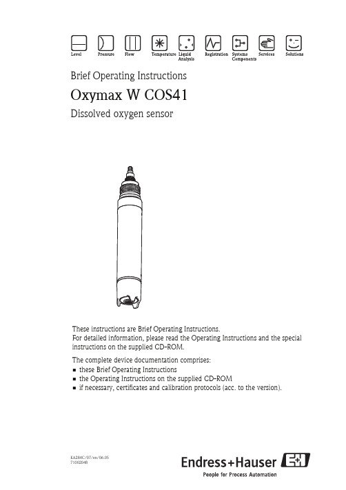
Brief Operating InstructionsOxymax W COS41Dissolved oxygen sensorThese instructions are Brief Operating Instructions.For detailed information, please read the Operating Instructions and the special instructions on the supplied CD-ROM.The complete device documentation comprises:•these Brief Operating Instructions•the Operating Instructions on the supplied CD-ROM•if necessary, certificates and calibration protocols (acc. to the version).KA284C/07/en/06.0571002048Table of contents Oxymax W COS41 Table of contents1 Safety instructions. . . . . . . . . . . . . . . . . . . . . . . . . . . . . . . . . . . . . . . . . . . . . . . . . 21.1 Designated use . . . . . . . . . . . . . . . . . . . . . . . . . . . . . . . . . . . . . . . . . . . . . . . . . . . . . . . . . . . . . . . . . . . . . . . . . . 21.2 Installation, commissioning and operation . . . . . . . . . . . . . . . . . . . . . . . . . . . . . . . . . . . . . . . . . . . . . . . . . . . . . . 21.3 Operational safety . . . . . . . . . . . . . . . . . . . . . . . . . . . . . . . . . . . . . . . . . . . . . . . . . . . . . . . . . . . . . . . . . . . . . . . . 32 Installation. . . . . . . . . . . . . . . . . . . . . . . . . . . . . . . . . . . . . . . . . . . . . . . . . . . . . . 32.1 Installation conditions . . . . . . . . . . . . . . . . . . . . . . . . . . . . . . . . . . . . . . . . . . . . . . . . . . . . . . . . . . . . . . . . . . . . . 32.2 Installation instructions . . . . . . . . . . . . . . . . . . . . . . . . . . . . . . . . . . . . . . . . . . . . . . . . . . . . . . . . . . . . . . . . . . . . 42.3 Installation examples . . . . . . . . . . . . . . . . . . . . . . . . . . . . . . . . . . . . . . . . . . . . . . . . . . . . . . . . . . . . . . . . . . . . . 52.4 Post installation check . . . . . . . . . . . . . . . . . . . . . . . . . . . . . . . . . . . . . . . . . . . . . . . . . . . . . . . . . . . . . . . . . . . . 83 Wiring . . . . . . . . . . . . . . . . . . . . . . . . . . . . . . . . . . . . . . . . . . . . . . . . . . . . . . . . . 93.1 Direct connection to the transmitter . . . . . . . . . . . . . . . . . . . . . . . . . . . . . . . . . . . . . . . . . . . . . . . . . . . . . . . . . . 93.2 Connection via junction box . . . . . . . . . . . . . . . . . . . . . . . . . . . . . . . . . . . . . . . . . . . . . . . . . . . . . . . . . . . . . . . 104 Commissioning. . . . . . . . . . . . . . . . . . . . . . . . . . . . . . . . . . . . . . . . . . . . . . . . . . 114.1 Function check . . . . . . . . . . . . . . . . . . . . . . . . . . . . . . . . . . . . . . . . . . . . . . . . . . . . . . . . . . . . . . . . . . . . . . . . . 114.2 Polarization . . . . . . . . . . . . . . . . . . . . . . . . . . . . . . . . . . . . . . . . . . . . . . . . . . . . . . . . . . . . . . . . . . . . . . . . . . . 114.3 Calibration . . . . . . . . . . . . . . . . . . . . . . . . . . . . . . . . . . . . . . . . . . . . . . . . . . . . . . . . . . . . . . . . . . . . . . . . . . . . 121Safety instructions1.1Designated useThe oxygen sensor is suitable for continuous measurement of dissolved oxygen in water.Typical applications are:•Measuring, monitoring and regulating the oxygen content in activated sludge basins.•Monitoring the oxygen content in the sewage treatment plant outlet.•Monitoring, measuring and regulating the oxygen content in public waters and fish farming water.•Monitoring of oxygen enrichment in drinking water.Any other use than the one described here compromises the safety of persons and the entire measuring system and is, therefore, not permitted.The manufacturer is not liable for damage caused by improper or non-designated use.1.2Installation, commissioning and operation•The device/measuring system may only be installed, connected, operated and maintained by trained technical personnel (e.g. certified electrician). The technical personnel must strictlyadhere to the Operating Instructions, prevailing standards, legal regulations and certificates(depending on application).•If the Brief Operating Instructions do not provide sufficient information, you must read theOperating Instructions. There, you can find detailed information on the device.2Endress+HauserOxymax W COS41InstallationEndress+Hauser 3•The operator may only perform modifications and repairs of the device/measuring system that are explicitly permitted in the Operating Instructions.•Do not operate damaged products and secure them against unintentional commissioning. Mark the damaged product as being defective.•If faults can not be rectified, the products must be taken out of service and secured against unintentional commissioning.1.3Operational safetyThe sensor has been designed and tested according to the state of the art and left the factory in perfect functioning order.Relevant regulations and European standards have been met.As the user, you are responsible for complying with the following safety conditions: •Installation instructions•Local prevailing standards and regulations."Caution!Pay attention to the technical data on the name plate!2Installation2.1Installation conditions2.1.1OrientationOther angles are not permitted. Do not install the sensor overhead.Fig. 1: Angle of installation ARecommended angle of installation: 0 ... 180 °Installation Oxymax W COS414Endress+Hauser2.1.2Mounting location•Select the installation location so that there is easy access for later calibration.•Make sure that upright posts and assemblies are secured safely and vibration-free.•For immersed operation in an activated sludge basin, select an installation location which produces a typical oxygen concentration.2.2Installation instructions2.2.1Installing a measuring point!Note!For immersed operation, install the individual modules away from the basin on a solid base. Only carry out the final installation at the intended installation location.For a complete installation of a measuring point, proceed as follows:1.Install a retractable or a flow assembly (if used) into the process.2.Connect the water supply to the rinse connections (if you use an assembly with cleaning function).3.Install and connect the oxygen sensor.4.Install an immersion or an suspension assembly (if used) into the process."Caution!•For immersed operation, the sensor must be installed in an immersion assembly (e.g. CYA611). Do not install the sensor suspended from the cable.•Screw the sensor into the assembly so that the cable is not twisted.•Avoid exerting excessive tensile force on the cable (e.g. from jerky pulling).•Select the installation location so that there is easy access for later calibration.#Warning!When using metallic assemblies and installation equipment, comply with national grounding regulations.Oxymax W COS41InstallationEndress+Hauser 52.3Installation examples2.3.1Immersion operationUniversal assembly holder and chain assemblyFig. 2: CYH101 with immersible pendulum assembly 1Weather protection cover2Upright post, square pipe SS AISI 3043Transverse pipe SS AISI 3044Star handle5Second fixing possibility for transverse pipe 6Immersion assembly CYA 611Fig. 3: Immersion assembly CYA 6111Protection cap2Worm drive hose clip3Pipe clips (detailed drawing in right half)4PVC pipe5Threaded couplingInstallation Oxymax W COS41 Universal assembly holder and fixed immersion assemblyFig. 4: Universal suspension assembly holder CYH101 with immersion assembly CYY1051Star handle2Pipe holder3Fixing bracket4Immersion assembly (= immersion tube)6Endress+HauserOxymax W COS41InstallationEndress+Hauser 7Basin rim mounting with immersion tubeFloating bodyFig. 5: Horizontal basin rim mounting 1Protection cover for cable entry 2Assembly holder3Immersion assembly SS 1.4301 (AISI 304)Fig. 6: Vertical basin rim mounting 4Basin rim mounting 5Star handleFig. 7: Floating body1234567Cable route with strain relief and rain protection Mounting ring for ropes and chains with locking screwLugs Ø15, 3 x 120 ° for anchoring Saltwater-resistant plastic floatPipe 40x1, stainless steel 1.4571 (AISI 316Ti)Shock absorber and weight Oxygen sensorInstallation Oxymax W COS418Endress+Hauser2.3.2Flow assembly2.4Post installation check•Check the membrane for leak tightness und replace it if necessary.•Sensor and cable undamaged?•Compliance with permissible sensor installation position?•Is the sensor installed in an assembly and is not suspended from the cable?•Avoid moisture by rain by fitting the protective cap to the immersion assembly?Fig. 8: Flow assembly COA250-B 1Screw-in part for sensor 2Screw ring 3Meter body4Connection thread G¾5Dummy plug (connection for spray head COR3)Fig. 9: Bypass installation1Main line 2Medium return 3Oxygen sensor4, 7Manually actuated or solenoid valves 5Flow assembly COA250-B 690 ° pipe bracket 8Medium removalOxymax W COS41WiringEndress+Hauser 93Wiring#Warning!•The electrical connection must only be carried out by a certified electrician.•Technical personnel must have read and understood the instructions in this manual and must adhere to them.•Ensure that there is no voltage at the power cable before beginning the connection work.3.1Direct connection to the transmitterThe sensor is connected using a special measuring cable (→å 10). The wiring diagram is contained in the Operating Instructions of the COM223/253-DX/DS transmitter.!Note!The interior white and yellow pilot wires have no function.Fig. 10: Special measuring cable CYK 71Terminal S 12909111AssignmentOuter shieldActive inner shield (NTC)Cathode AnodeNTC temperature sensorWiring Oxymax W COS413.2Connection via junction boxTo lengthen the sensor connection beyond the length of the fixed cable, you require a junction box VBM. The connection is lengthened to the transmitter using the special measuring cable CYK71.Fig. 11: Connection via junction box VBM1Sensor2Junction box3Extension cable4Transmitter10Endress+HauserOxymax W COS41CommissioningEndress+Hauser 114Commissioning 4.1Function checkBefore first commissioning, check if:•the sensor is correctly installed•the electrical connection is correct.If using an assembly with automatic cleaning, check the correct water connection at theassembly rinse connection.#Warning!Danger of medium leaking offBefore applying compressed air to an assembly with cleaning facility, make sure the connections are correctly fitted. Otherwise, the assembly may not be insert into the process.4.2PolarizationThe sensor was tested in the factory for perfect functionality and is supplied ready for operation.To prepare for calibration, proceed as follows:1.Remove the sensor protective cap.2.Place the externally dry sensor in atmospheric air. The air should be saturated with watervapour. Therefore, install the sensor as close to the water surface as possible. Whencalibrating the sensor membrane, make sure the membrane remains dry. Therefore, avoidany direct contact with the water surface.3.Connect the sensor to the transmitter and switch on the transmitter.4.Switch-on the transmitter.If you connect the sensor to the transmitter Liquisys M COM223/253, polarisation isautomatically performed after switching on the transmitter.5.The polarisation time takes about 1 hour.!Note! Polarisation starts high, then drops gradually. You will recognise the end of polarisation when the display stabilises and remains practically constant."Caution!•When you remove the sensor from the medium, protect the sensor from strong sunlight.•Make sure you comply with the instructions for commissioning and calibration in theOperating Instructions of the transmitter.4.3CalibrationCalibrate the sensor (calibration type "Air") immediately after it’s polarization.1.Remove the sensor from the medium.2.Clean the outside of the sensor with a damp cloth. Then dry the sensor membrane e.g.by using a tissue.3.If the sensor is removed from a closed pressure system with a process pressure greaterthan atmospheric pressure:–Open the membrane cap to equilibrate the pressure and clean the cap if necessary.–Replace the electrolyte filling and close the membrane cap again.–Wait for the polarisation time to end.4.Then wait while the sensor adjusts to the temperature of the ambient air. This takesabout 20 minutes. Check that the sensor is not in direct sunlight during this time.5.If the measured value display on the transmitter is stable, carry out the calibration inaccordance with the Operating Instructions of the transmitter.6.Place the sensor in the medium again.!Note!Make sure you comply with the instructions for calibration in the Operating Instructions of the transmitter./worldwideKA284C/07/en/06.05Printed in Germany / FM+SGML 6.0 /DT71002048。
Endress+Hauser Oxymax COS61D 产品说明说明书
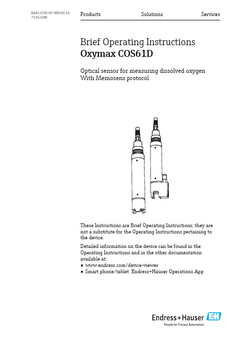
Products Solutions Services Brief Operating Instructions Oxymax COS61DOptical sensor for measuring dissolved oxygenWith Memosens protocolThese Instructions are Brief Operating Instructions; they arenot a substitute for the Operating Instructions pertaining tothe device.Detailed information on the device can be found in theOperating Instructions and in the other documentationavailable at:•/device-viewer•Smart phone/tablet: Endress+Hauser Operations AppKA01133C/07/EN/02.1671341288Oxymax COS61DEndress+Hauser Operations App 2Endress+HauserOxymax COS61D Table of contentsEndress+Hauser 3Table of contents1Document information (4)1.1Warnings ............................................................................41.2Symbols (4)2Basic safety instructions (5)2.1Requirements for the personnel ............................................................52.2Designated use ........................................................................52.3Occupational safety .....................................................................52.4Operational safety ......................................................................62.5Product safety .........................................................................63Installation (7)3.1Installation conditions ...................................................................73.2Mounting the sensor ....................................................................83.3Installation examples ..................................................................103.4Post-installation check (15)4Electrical connection (16)4.1Connecting the sensor ..................................................................164.2Ensuring the degree of protection .........................................................164.3Post-connection check (16)5Commissioning (18)5.1Function check .......................................................................185.2Sensor calibration .....................................................................185.3Cleaning the sensor automatically (18)Document information Oxymax COS61D 1 Document information1.1 Warnings1.2 Symbols4Endress+HauserOxymax COS61D Basic safety instructionsEndress+Hauser 52Basic safety instructions2.1Requirements for the personnel•Installation, commissioning, operation and maintenance of the measuring system may be carried out only by specially trained technical personnel.•The technical personnel must be authorized by the plant operator to carry out the specified activities.•The electrical connection may be performed only by an electrical technician.•The technical personnel must have read and understood these Operating Instructions and must follow the instructions contained therein.•Measuring point faults may be repaired only by authorized and specially trained personnel.Repairs not described in the Operating Instructions provided may only be carried out directly by the manufacturer or by the service organization.2.2 Designated useThe oxygen sensor is suitable for continuous measurement of dissolved oxygen in water.The main areas of application are:•Wastewater treatment plants–Oxygen measurement and regulation in the activated sludge basin for a highly efficient biological cleaning process–Monitoring the oxygen content in the wastewater treatment plant outlet •Water monitoringOxygen measurement in rivers, lakes or seas as an indicator of the water quality •Water treatmentOxygen measurement for status monitoring, e.g. of drinking water (oxygen enrichment,corrosion protection etc.)•Fish farmingOxygen measurement and regulation for optimum living and growth conditions Use of the device for any purpose other than that described, poses a threat to the safety of people and of the entire measuring system and is therefore not permitted.The manufacturer is not liable for damage caused by improper or non-designated use.2.3 Occupational safetyAs the user, you are responsible for complying with the following safety conditions:•Installation guidelines•Local standards and regulationsElectromagnetic compatibility•The product has been tested for electromagnetic compatibility in accordance with the applicable European standards for industrial applications.•The electromagnetic compatibility indicated applies only to a product that has been connected in accordance with these Operating Instructions.Basic safety instructions Oxymax COS61D6Endress+Hauser2.4Operational safety1.Before commissioning the entire measuring point, verify that all connections are correct. Ensure that electrical cables and hose connections are undamaged.2.Do not operate damaged products, and safeguard them to ensure that they are not operated inadvertently. Label the damaged product as defective.3.If faults cannot be rectified:Take the products out of operation and safeguard them to ensure that they are not operated inadvertently.Non-designated useIncorrect measurements, malfunctions and even measuring point failure could result ‣Only use the product in accordance with the product specifications.‣Pay particular attention to the technical data on the nameplate.2.5 Product safetyThe product is designed to meet state-of-the-art safety requirements, has been tested, and left the factory in a condition in which it is safe to operate. The relevant regulations and European standards have been observed.Oxymax COS61D InstallationEndress+Hauser 73Installation3.1Installation conditions3.1.1Orientation1Angle of installationRecommended angle of inclinationThe sensor must be installed at an angle of inclination in an assembly, bracket or appropriate process connection. Recommended angle: 45°, to prevent the formation of air bubbles. At angles of inclination of 45 to 135°, air bubbles at the oxygen-sensitive membrane may increase the measured value.The sensor can be installed up to the horizontal in an assembly, support or suitable process connection. The optimum installation angle is 45°.Other angles and upside-down installation are not recommended. Reason: Possible sediment formation and resulting falsification of measured value.Observe the instructions for installing sensors in the Operating Instructions for the assembly used.3.1.2Mounting location•Choose a mounting location that can be easily accessed at a later stage.•Ensure that upright posts and fittings are fully secured and vibration-free.•Select an installation location which produces a typical oxygen concentration for the individual application.Installation Oxymax COS61D8Endress+Hauser3.2Mounting the sensor3.2.1 Mounting the cleaning unitIf the cleaning unit is not supplied in a preassembled state:1.Unscrew the protection guard.Retain the protection guard for possible reuse at a later stage without the cleaningunit.2.Carefully screw on the shaft sleeve as far as it will go.The cleaning nozzle should now be level with the spot.1Cleaning nozzle 2SpotOxymax COS61D InstallationEndress+Hauser93.Connect the hose for the compressed air supply (to be provided onsite) or compressor to the hose connection of the cleaning unit.3.2.2Installing a measuring pointInstallation in suitable assembly is required (depending on the application)L WARNINGElectrical voltageIn the event of a fault, non-grounded metallic assemblies may be under voltage and then are not touchable.‣When using metallic assemblies and installation equipment, observe the nationalgrounding provisions.For immersion operation, install the individual modules away from the basin on a solid base. Only carry out the final installation at the intended installation location. Select an installation location that is easy to access.For a complete installation of a measuring point, proceed as follows:1.Install a retractable or a flow assembly (if used) into the process.2.Connect the water supply to the rinse connections (if you use an assembly with cleaning function).3.Install and connect the oxygen sensor.Installation errorCable open circuit, loss of sensor due to cable separation, unscrewing of fluorescence cap ‣Do not install the sensor suspended from the cable.‣Screw the sensor into the assembly so that the cable is not twisted.‣When installing or uninstalling the sensor body, hold it tightly. Turn using only the hexagonal nut on the armored coupling. Otherwise you might unscrew the fluorescence cap. This will then remain in the assembly or process.‣Avoid exerting excessive tensile force on the cable (e.g. from jerky pulling).‣Select an installation location that is easy to access for later calibrations.‣Observe the instructions for installing sensors in the Operating Instructions for the assembly used.Installation Oxymax COS61D10Endress+Hauser3.3Installation examples3.3.1Immersion operationUniversal holder and chain assembly2Chain holder on railing1Chain2Holder Flexdip CYH1123Rail4Sensor Oxymax5Wastewater assembly Flexdip CYA1123Chain holder on upright post 1Weather protection cover CYY1012Controller / transmitter 3Chain4Wastewater assembly Flexdip CYA1125Sensor Oxymax6Holder Flexdip CYH112Oxymax COS61D Installation Universal holder and fixed immersion tube4Assembly holder with immersion tube1Protective cover2Controller / transmitter3Flexdip CYA112 immersion assembly4Sensor Oxymax5Assembly holder Flexdip CYH112Endress+Hauser11Installation Oxymax COS61D Basin rim mounting with immersion tube5Basin rim mounting1Pendulum holder CYH1122Assembly Flexdip CYA1123Assembly float4Sensor Oxymax12Endress+HauserOxymax COS61D Installation Endress+Hauser 13FloatThe CYA112 float is for use in the case of large fluctuations in water level, for example in rivers or lakes.6Dimensions in mm (inch)1Cable run with strain relief and rain shield 2Fixing ring for rope and chains with terminal screw3Eyelets Ø15, 3 x 120 ° for anchoring 4Plastic float, resistant to salt water 5Pipe 40 x 1, stainless steel 1.45716Bumper and ballast 7Oxygen sensorInstallation Oxymax COS61D14Endress+Hauser3.3.2Flow assembly COA2507COA250 8Bypass installation with manually actuated valves or solenoid valves 1Main pipe 2Medium return 3Oxygen sensor 4, 7Manually actuated or solenoid valves 5Flow assembly COA250-A 690 ° pipe elbow 8Medium removalOxymax COS61D InstallationEndress+Hauser 153.3.3 Retractable assembly COA4519Permissible and impermissible sensor installation positions with retractable assembly COA4511Ascending pipe, best position 2Horizontal pipe, sensor top down, impermissible due to air cushion or foam bubble forming 3Horizontal pipe, lateral installation with permissible installation angle (acc. to sensor version)4Down pipe, impermissibleNOTICESensor not fully immersed in the medium, deposit on sensor membrane or sensor optics,sensor installed upside down Incorrect measurements are possible and these may affect the measuring point.‣Do not install the assembly at points where air pockets or bubbles form or where suspended particles may build up at the sensor membrane or sensor optics (item 2).3.4Post-installation check •Are the sensor and cable undamaged?•Is the orientation correct?•Is the sensor installed in an assembly and is not suspended from the cable?•Avoid the penetration of moisture by fitting the protective cap to the immersion assembly.Electrical connection Oxymax COS61D 16Endress+Hauser4 Electrical connectionL WARNINGDevice is live Incorrect connection may result in injury or death ‣The electrical connection may be performed only by an electrical technician.‣The electrical technician must have read and understood these Operating Instructions and must follow the instructions contained therein.‣Prior to commencing connection work, ensure that no voltage is present on any cable.4.1 Connecting the sensorConnection data •Sensor cable connected directly to the terminal connector of the basic module •Optional: Sensor cable plug connected to the M12 sensor socket on the underside of the transmitter With this type of connection, the transmitter is already wired at the factory.10Sensor fixed cable with terminated cable cores4.2 Ensuring the degree of protectionOnly the mechanical and electrical connections which are described in these instructions and which are necessary for the required, designated use, may be carried out on the device delivered.‣Exercise care when carrying out the work.Otherwise, the individual types of protection (Ingress Protection (IP), electrical safety, EMC interference immunity) agreed for this product can no longer be guaranteed due, for example,to covers being left off or cable (ends) which are loose or insufficiently secured.4.3 Post-connection checkOxymax COS61D Electrical connectionEndress+Hauser17Commissioning Oxymax COS61D 18Endress+Hauser5Commissioning 5.1 Function checkBefore first commissioning, check if:•the sensor is correctly installed •the electrical connection is correct.If using an assembly with automatic cleaning, check that the cleaning medium (e.g. water or air) is connected correctly.L WARNINGEscaping process medium Risk of injury from high pressure, high temperatures or chemical hazards ‣Before applying compressed air to an assembly with cleaning facility, make sure the connections are correctly fitted.‣Do not install the assembly in the process if you cannot make the correct connection reliably.5.2Sensor calibration The sensor is calibrated at the factory. A new calibration is only needed in special situations.5.3 Cleaning the sensor automatically Compressed air is most suitable for cyclic cleaning. The cleaning unit is either provided or can be retrofitted, and is attached to the sensor head. It operates at a capacity of 20-60 l/min.Optimum results are achieved at 2 bar (29 psi) and 60 l/min.The following settings are recommended for the cleaning unit:*71341288*71341288。
溶解氧传感器工作原理

溶解氧传感器工作原理
溶解氧传感器的工作原理如下:
1. 溶解氧传感器是一种用于测量液体中溶解氧浓度的传感器。
它通常由两个电极组成:阳极和阴极。
2. 阳极通常是一根银棒,而阴极则是由铂制成的线丝。
3. 在传感器工作时,阳极和阴极浸入待测液体中。
4. 当液体中存在溶解氧时,氧气分子会在阴极表面还原成氢离子。
5. 阳极则会接受这些氢离子,并将其氧化成水。
6. 在阳极和阴极之间,会形成一个电流,其强度与液体中溶解氧浓度成正比。
7. 通过测量这个电流,可以确定液体中的溶解氧浓度。
8. 通常情况下,溶解氧传感器会和温度传感器结合在一起,以补偿温度对溶解氧测量的影响。
总的来说,溶解氧传感器通过测量液体中溶解氧引起的电流变化,来确定液体中的溶解氧浓度。
氧分析仪的工作原理
氧分析仪的工作原理氧分析仪的工作原理在现在的工业环境中,氧气的含量对工业生产有着重要的作用,因此经常对其测量。
仪器市场上的产品多种多样,但是就测量原理来分,主要有2中测量方法:(1)热磁式氧分析仪其原理是利用烟气组分中氧气的磁化率特别高这一物理特性来测定烟气中含氧量。
氧气为顺磁性气体(气体能被磁场所吸引的称为顺磁性气体),在不均匀磁场中受到吸引而流向磁场较强处。
在该处设有加热丝,使此处氧的温度升高而磁化率下降,因而磁场吸引力减小,受后面磁化率较高的未被加热的氧气分子推挤而排出磁场,由此造成“热磁对流”或“磁风”现象。
在一定的气样压力、温度和流量下,通过测量磁风大小就可测得气样中氧气含量。
由于热敏元件(铂丝)既作为不平衡电桥的两个桥臂电阻,又作为加热电阻丝,在磁风的作用下出现温度梯度,即进气侧桥臂的温度低于出气侧桥臂的温度。
不平衡电桥将随着气样中氧气含量的不同,输出相应的电压值。
(2)氧化锆传感器式氧分析仪氧化锆(ZrO2)是一种陶瓷,一种具有离子导电性质的固体。
在常温下为单斜晶体,当温度升高到1150℃时,晶型转变为立方晶体,同时约有7%的体积收缩;当温度降低时,又变为单斜晶体。
若反复加热与冷却,ZrO2就会破裂。
因此,纯净的ZrO2不能用作测量元件。
如果在ZrO2中加入一定量的氧化钙(CaO)或氧化钇(Y2O3)作稳定剂,再经过高温焙烧,则变为稳定的氧化锆材料,这时,四价的锆被二价的钙或三价的钇置换,同时产生氧离子空穴,所以ZrO2属于阴离子固体电解质。
ZrO2主要通过空穴的运动而导电,当温度达到600℃以上时,ZrO2就变为良好的氧离子导体。
氧分析仪,该产品重量轻,所以携带方便,小功率操作(GPR-1100充电一次可连续操作30天,超过8小时的内部泵运行),并可测量小于10ppm的氧含量。
使用过程中,用户喜欢简单直观的操作,搭配一个坚固的外壳,防止重工业环境下的意外损坏。
为了最大限度的提高氧分析仪寿命,的结构中有一个快速连接件,用来保护仪器不工作时传感器暴露在空气中所带来的损坏,这样传感器寿命可达用户所期望的24个月。
溶解氧测试仪的原理

溶解氧测试仪的原理在污水处理过程中,通过增加污水中的氧含量使污染物通过活化泥浆被分解出来,达到污水净化的目的,测量氧含量有助于确定最佳的净化方法和最经济的曝气池配置。
在生物发酵过程中氧含量的测量数据可对工艺过程进行指导,如判断发酵过程的临界氧浓度、发酵罐的供氧能力以及菌体的活性和菌体的生长量等,并根据发酵时的供氧和需氧变化来指导补料操作。
一、溶解氧分析仪测量原理氧在水中的溶解度取决于温度、压力和水中溶解的盐。
溶解氧分析仪传感部分是由金电极(阴极)和银电极(阳极)及氯化钾或氢氧化钾电解液组成,氧通过膜扩散进入电解液与金电极和银电极构成测量回路。
当给溶解氧分析仪电极加上0.6~0.8V 的极化电压时,氧通过膜扩散,阴极释放电子,阳极接受电子,产生电流,整个反应过程为:阳极Ag+Cl→AgCl+2e- 阴极O2+2H2O+4e→4OH- 根据法拉第定律:流过溶解氧分析仪电极的电流和氧分压成正比,在温度不变的情况下电流和氧浓度之间呈线性关系。
二、溶解氧含量的表示方法溶解氧含量有3 种不同的表示方法:氧分压(mmHg);百分饱和度(%);氧浓度(mg/L 或10-6),这3 种方法本质上没什么不同。
(1)分压表示法:氧分压表示法是最基本和最本质的表示法。
根据Henry 定律可得,P=(Po2+P H2O )×0.209,其中,P 为总压;Po2 为氧分压(mmHg);P H2O 为水蒸气分压;0.209 为空气中氧的含量。
(2)百分饱和度表示法:由于曝气发酵十分复杂,氧分压不能计算得到,在此情况下用百分饱和度的表示法是最合适的。
例如将标定时溶解氧定为100%,零氧时为0%,则反应过程中的溶解氧含量即为标定时的百分数。
(3)氧浓度表示法:根据Henry 定律可知氧浓度与其分压成正比,即:C=Po2 ×a,其中C 为氧浓度(mg/L);Po2 为氧分压(mmHg);a 为溶解度系数(mg/mmHg·L)。
西门子OXYMAT 61型氧气分析仪氧气浓度测量仪

参比气体
量程
0 ~ ...% v/v O2 …~ 100% v/v O2 (满刻度归零 100% v/v O2) 约 21% v/v O2 (21%v/v O2 下,量程范围内归零)
预处理系统的外部信号) • 六个继电器输出可自由配置 (例如:故障、维护请求、维护开
关、超限报警、外部电磁阀) • 两个可编程模拟量输入 (交叉干扰校正或外部压力传感器) • 八个扩展的二进制输入和八个继电器输出可用来进行多达四种
标气的自动标定
通讯 • RS 485 为基本配置
选项 • RS485/RS 232 的转接器 • RS485/ 以太网的转接器 • PROFIBUS-DP/-PA 网卡接入网络 • SIPROM GA 软件
(OX1)YM,A另T 一61种中是,样这气两(种5气)体。一参种比是气参经比过气两个(参N2比,气O通2 道或者(空3)气进) 入样气室 (6)。其中一路参比气在磁场区域 (7)和样气相遇。 因这两个通道是连通的,所以与氧浓度成正比的压力差使得两路 参比气在图 2 中位置 4 处形成气流。微流量传感器 (4)感知该 气流并将其转变为电信号。
如联需系购人买:此余产经品理欢迎联联系系电重话庆:艾18利28顿02自27动00氧化7 气O分XY析M仪AT 61
19" 机架式
■ 电气连接图
针脚分配 (电气连接)
OXYMAT 61, 19" 机架式,针脚分配
7
OXY氧M气AT分6析1 如仪联需系购人买:此余产经品理欢迎联联系系电重话庆:艾18利28顿02自27动00化7
- 1、下载文档前请自行甄别文档内容的完整性,平台不提供额外的编辑、内容补充、找答案等附加服务。
- 2、"仅部分预览"的文档,不可在线预览部分如存在完整性等问题,可反馈申请退款(可完整预览的文档不适用该条件!)。
- 3、如文档侵犯您的权益,请联系客服反馈,我们会尽快为您处理(人工客服工作时间:9:00-18:30)。
测量电缆 接线盒
· 测量电缆OMK 用于接线盒和变送器之间的延长电缆,长度没有限制; 按“米”销售-订货号:50004124
·VS接线盒 带插拔式插座和7针插头 用于延长从探头到变送器的连接电缆,IP65防护等级 订货号:50001054
·测量结果: - 探头给出一个与介质中氧浓度相关的信号。 -流体温度和空气压力影响已考虑在探头测量内。
光学信号可以连续测量,可靠地分析 当有故障发生时,会在变送器中发出出错信息
自动监测探头老化,一段时期后变送器会显示一个预先维护的报警信息,到期未维护会产 生一个出错信息。
另外,通过Liquisys M COM2x3 仪表的探头自检测系统,会将下列测量 故障也显示出来: ·测量结果不可信地过高或过低 ·因不正常测量而造成的明显干扰
·污水处理厂 活性污泥池中氧的测量和调节,以便在生物降解过程中
达到最高效
·水文监测 测量河流、湖泊、海洋中的含氧量,从而指示水的质量
·水处理 氧气测量,对饮用水的状态检测(富氧量/腐蚀预防等)
·渔场 氧气的测量和调节以便维持最佳的生存和生长环境
优点
·光电技术 -维护率低 -可靠性高
·与带COM2x3W 兼容,替代目前使用良好的COS31 探头 -光电技术能方便地改变测量点
图1:测量系统 1 浸入式支架CYA611 2 VS接线盒(备选) 3 Liquisys M COM253 变送器 4 测量电缆,备选扩展电缆 5 探头电缆 6 溶解氧探头 COS61
2
输入
测量变量
测量范围
环境
环境温度范围 储存温度 防护等级
过程
过程温度 过程压力
性能特点
响应时间t90 最大测量误差 重现性 传感器帽寿命
6
TI 387C/28/zh/ (03.08)
·与带COM2x3D(带转换套件)兼容,替代COS41 探头
·带数字信号处理的传感器 -标定数据储存在传感器内 通信实现高度的EMC 保护
-与变送器的数字
·长期稳定性高,维护率低
·智能自检确保测量值的可靠性
·无流速要求,测量可在静水中进行
TI38 7C/28 /zh /( 0 3.08)
功能和系统设计
溶解氧[ mg/l,%SAT,hPa] 温度[ ℃,°F ] 与变送器Liquisys M COM223/253 配合使用: 0 ...20 mg/l(0...20ppm) 0 ...200 % SAT 0 ...400 hPa
-20...+60 ℃(-4到140°F ) -20...+70 ℃(-4...158°F ) 95%相对湿度,无冷凝 IP 68
-5...+50 ℃(23...122°F ) 最大允许过压:10bar(145psi)
t90:60s ±2%量程范围 ±0.5%量程范围 1年(避免阳光直射)
3
机械结构
设计,尺寸
重量
材质
过程 传感器电缆 变送器电缆入口 电缆规格 温度补偿 串行接口
φ40/1.57 固定电缆型
TOP68 型
φ40/1.57
·沉入式安装支架DipfitCW Y A6 11 用于敞口池、明渠和罐体的安装,PVC; 按照订货信息定购(技术资料TI166C/07/en)
·流通式安装支架 COA 250 用于探头在管道上的安装,PVC; 按照订货信息定购(技术资料TI 111C/07/en)
·伸缩式安装支架CleanfitCOA4 51 手动操作的伸缩式支架,不锈钢材质,带球阀,用于溶氧探头; 按照订货信息定购(技术资料TI368C107/en)
完整的测量系统: ·溶解氧探头 ·变送器,如 Liquisys M COM 223/253 ·可根据需要配特殊长度电缆 · 附件:流通式支架COA 250 、插入式支架CYA 611 或插入式可伸缩支架COA451
备选: ·用于固定插入式安装杆的通用框架式固定支架CYH101 ·VS接线盒(用于扩展电缆) ·Chemclean 自动清洗系统
Level
Pressure
Flow
Temperature Liquid Analysis
Registration System
Services
Components
Solutions
技术资料 Oxymax W COS61 溶解氧探头 基于荧光法原理的光电传感器
应用
水中溶解氧浓度的连续测量在许多场合起着非常重要的作用:
带7m(22.97ft)长电缆:0.7kg(1.5lb.) 带15m(49.22ft)长电缆:1.1kg(2.4lb.) 带TOP68 插装头连接:0.3kg(0.7lb.)
传感器主体: 荧光层帽: 荧光层:
不锈钢1.4571(AISI 316Ti) POM 硅
G1
带屏蔽的7芯固定电缆或者带4针航空接头的双屏蔽的同轴电缆。
测量原理
探头测量 测量系统
·探头结构: -氧敏感分子(标记体)集成于光学活性层内(荧光层)。 -荧光层表面直接与被测介质接触。 -探头光路系统直接安装在荧光层背面。
·介质中的氧分压与荧光层内的压力平衡: -一旦探头插入测量介质中,此平衡会立刻达到。
·测量过程: -探头内光路系统将脉冲绿色光束打到荧光层。 -标记体以脉冲红光受激“响应”(发荧光)。 -受激反应信号的持续时间和强度直接与氧的成份和分压有关。 -若介质中不含任何氧,响应信号会很长,并很强。 -因氧分子会淬灭标记体分子,这样,也就使得响应信号变短变弱。
探头 F G1,带SXP插头的固定电缆 S G1,TOP68插头
附件 0 无附件
完整产品型号
供货范围 ·氧传感器,带运输帽 ·操作指南,英文
5
附件
安装件(选配)
通用型 沉入式安装悬挂支架
·沉入式安装支架 COA 110 用于敞口池的沉入式安装,PVC管道以及PUR浮箱安装,带SS1.4571(A1SI 316Ti)插入 管; 按照订货信息定购(技术资料TI035C/07/en)
·SXP 插头(现场设备) ·端子连接(盘式安装设备)
最大100m/328ft(包括扩展电缆)
内置温度传感器
RS485
4
证书和认证EMC兼容性订货来自息选型表供货范围
干扰辐射和抗干扰符合EN61326:1997/A1:1998
COS61-
证书 A 无防爆
电缆长度 0 电缆长度:1.5m(4.9ft) 1 电缆长度:7.5m(23ft) 2 电缆长度:15m(49ft) 8 无电缆(用于TOP68型插头) 9 根据客户需要的特殊要求