PIC18F87K22系列与XLP 8位开发板主要特性
Microchip PIC18F87K22极低功耗8位MCU开发方案

Microchip PIC18F87K22极低功耗8位MCU开发方案公司的18F87K22系列是采纳极低功耗(nanoWatt XLP)技术的高性能,集成了1Mb增加性闪存和24路12位,具有高达16性能,8x8单周期硬件乘法器,工作频率高达64MHz,工作1.8V-5.5V,有10个CCP/ECCP模块,11个8/16位定时器/计数器模块,两个主同步串口模块,特殊适用于功率有严格要求和以电池为能源的应用.本文介绍了PIC18F87K22低功耗特性,MCU特性以及外设特性, 方框图以及XLP 8位开发板主要特性,主要元件及分布图以及.PIC18F87K22 Family 64/80-Pin, High-Performance, 1-Mbit Enhanced Flash Microcontrollers with 12-Bit A/D and nanoWatt XLPTechnologyThis document contains device-specific information for the following devices: This family combines the traditional advantages of all PIC18 microcontrollers – namely, high computational performance and a rich feature set – with an extremely competitive price point. These features make the PIC18F87K22 family a logical choice for many high-performance applications where price is a primary consideration.PIC18F87K22低功耗特性:Power-Managed modes:- Run: CPU on, peripherals on- Idle: CPU off, peripherals on- Sleep: CPU off, peripherals offTwo-Speed Oscillator Start-upFail-Safe Clock MonitorPower-Saving Peripheral Module Disable (PMD)第1页共4页。
PIC18F8723 数据手册
• 2 个带输入复用的模拟比较器 • 高灌 / 拉电流:25 mA/25 mA • 4 个可编程外部中断 • 4 个输入电平变化中断
外部存储器接口:
• 寻址能力最高可达 2 MB • 8 位或 16 位接口 • 8 位、 12 位、 16 位和 20 位地址模式
注 1: ECCP2/P2A 引脚位置取决于 CCP2MX 配置位的设置。
DS39894A_CN 第2 页
初稿
2007 Microchip Technology Inc.
引脚图 (续)
80 引脚 TQFP
PIC18F8723
RH1/A17 RH0/A16 RE2/AD10/CS/P2B RE3/AD11/P3C(2) RE4/AD12/P3B(2) RE5/AD13/P1C(2) RE6/AD14/P1B(2) RE7/AD15/ECCP2(1)/P2A(1) RD0/AD0/PSP0 VDD VSS RD1/AD1/PSP1 RD2/AD2/PSP2 RD3/AD3/PSP3 RD4/AD4/PSP4/SDO2 RD5/AD5/PSP5/SDI2/SDA2 RD6/AD6/PSP6/SCK2/SCL2 RD7/AD7/PSP7/SS2 RJ0/ALE RJ1/OE
RE1/WR/P2C RE0/RD/P2D RG0/ECCP3/P3A RG1/TX2/CK2 RG2/RX2/DT2 RG3/CCP4/P3D RG5/MCLR/VPP RG4/CCP5/P1D
VSS VDD RF7/SS1 RF6/AN11 RF5/AN10/CVREF RF4/AN9 RF3/AN8 RF2/AN7/C1OUT
Microchip新款高端8位PIC

Microchip 新款高端8 位PIC
美国微芯科技公司(Microchip Technology)近日宣布推出新款PIC18F 高端
8 位单片机系列产品。
与上一代产品相比,该系列产品的价格低了30%,配
备了可提高连接性能的更多串行端口,以及具备更快测量能力的快速模数转
换器(ADC)。
凭借纳瓦技术,新产品在上一代产品的基础上降低了40%的待
机电流和50%以上的工作电流。
目前,设计工程师面临与日俱增的挑战,既要满足用户对强大处理能力
和提升连通性的需求,又要进一步降低产品功耗和整体系统成本。
PIC18F8622/8527/6622/6527 系列单片机利用10 位100 ksps 模数转换器提高了性能,两个同步和两个异步串行端口扩展了通信能力,纳瓦技术和8 MHz
内置振荡器延长了电池寿命。
此外,Microchip 的MPLAB 开发工具支持
PIC18F8622,使其具有极佳的C 代码效率。
Microchip 先进单片机架构部副总裁Mitch Obolsky 表示:“PIC18F8622
系列单片机的推出,使Microchip 备受欢迎的PIC18F 高端8 位单片机系列遍
布48 至128 KB 的闪存产品,从而在采用纳瓦技术的产品间形成一条完整的
升级路径。
这一系列单片机的待机电流得到显着改善,非常适用于21 世纪复
杂的便携式应用。
”
PIC18F8622 系列可应用于:工业领域(HVAC、通信控制和电池供电的
仪器)及消费类产品(白色家电和电池供电的电子产品)。
PIC18FxxK22 Family - Rev1 - June10 - (8-bit Leadership Campaign)

June 2010 Rev - 1
Broadest Line of Low-Power, 5V 8-bit Microcontrollers
Fourteen new eXtreme Low Power PIC® MCUs
Industry-leading sleep current consumption Reduced active current consumption Ideal for battery-powered or power-constrained applications
2 2 2 2 2 2 2 2 2 2 3 3 3 3 3 3
0/1 0/1 1/1 1/1 2/3 2/3 1/1 1/1 2/3 2/3 5/3 7/3 7/3 5/3 7/3 7/3
N N Y Y Y Y Y Y Y Y Y Y Y Y Y Y
PIC18FXXK22 – 8-bit PIC® MCUs
EUSART 1 1 2 2 2 2 2 2 2 2 2 2 2 2 2 2
RAM
ADC
Pins
I/O
Summary
Fourteen new eXtreme Low Power PIC® MCUs Operating voltage range: 1.8 to 5.5V Scalability
20 pins to 80 pins 8 KB to 128 KB Flash memory
PIC18FXXK22 – 8-bit PIC® MCUs
Benefit
Battery life up to 20 years From single-cell battery applications to automotive and appliances Can drive multiple simultaneous functions, such as RGB LEDs, buzzers, motors, etc., and time multiple external events simultaneously High resolution for precision measurements in medical and metering applications Large number of cap.-touch sliders, buttons and keys Enhanced connectivity options for data logging, LIN, serial peripherals and memory
PIC18F单片机内核组成

PIC18F单片机内核组成
1.中央处理器(1)运算器:8 位运算/逻辑运算部件,累加器(工作寄存器W)
(2)8*8 硬件乘法器:可执行无符号运算,产生一个16 位运算结果
(3)控制单元:定时控制逻辑,RAM 文件寄存器,地址多路选择器,指令寄存器,文件选择寄存器
2.程序存储器和程序计数器
单片机内存放程序指令的存储器称为程序存储器。
程序计数器是21 位宽,可寻址2MB 的程序存储器空间
3.状态寄存器
PIC 单片机的状态寄存器是8 位寄存器,用来存放运算结果的一些特征
bit7~bit5:未用,该位读出时始终为0
bit4:N 表示负标志位,用于有符号的算术运算,结果表明是否为负数1=结果为负
0=结果为正
bit3:表示溢出为,用于有符号算术运算,表明溢出了7 位二进制数的范围1=算术运算或逻辑运算中发生溢出
0=没有发生溢出
bit2:Z 表示全0 标志位
1=算术运算或逻辑运算结果为0
0=算术运算或逻辑运算结果不为0
bit1:DC 表示辅助进位/借位标志位,用于
ADDWF、ADDLW、SUBLW、SUBWF。
pin18系列开发板应用说明

目前,在工业控制等应用领域中,大多数设备的通信接口都符合RS-232 通信标准。
RS-232 通信方式的数据传输半径十分有限,远远不能满足远程传输的需求,且不能与Internet 直接通信。
针对上述问题,在系统设计中,一般采用两种方法将串口设备进行有效改进后与Internet进行通信:①更新原有系统,采用能够接入Internet 的新产品,或者对原有系统的全部或局部进行重新设计。
这种方法可能从根本上解决系统连接到Internet 的问题,但是成本较高、周期较长;②在原来的设备上使用RS-232-Internet 的协议转换器,实现Internet 的接入。
本文主要讲述第二种方法,即如何利用P IC18F66J60 微控制器实现将因特网发送的数据包提取出来,通过串口送入用户设备,达到远程控制的目的。
1. 概述PIC18F66J60 微控制器实现的Ethernet- RS-232 协议转换器的Demo 板实物图如图1 所示,具有以下特征:①单芯片完成协议转换功能,大大降低系统成本和复杂程度。
②模块尺寸只有一张信用卡的一半大小,功耗不到1W,方便将其集成到系统设备中。
③ETORS232 内部集成TCP/IP 协议栈,用户无须编程TCP/IP 协议,即可将用户产品接入到以太网中。
④10MEthernet 接口,最大波特率为115200 b/s。
⑤支持动态(DHCP) 或静态获取IP地址。
⑥支持三种不同的网络连接模式:TCP SERVER 模式、TCP CLIENT 模式和UDP 模式。
⑦可以方便的使用Windows 应用程序NetConfig,进行网络参数查看和配置。
2. 硬件设计2.1 PIC18F66J60 微控制器PIC18F66J60芯片是Micro Chip公司新推出的一款以太网微控制器,具有出色的计算性能、丰富的功能集和极具竞争力的价格优势。
PIC18F66J60微控制器包含一系列串行通信外设:2 个独立的增强型US ART 和2个主控SSP 模块,能够进行SPI 和I2CTM(主控和从动)模式操作;通用I/O 端口中包含一个可重新配置为8 位并行从动端口,用于处理器之间的通信;本系列的所有器件均包含2 个捕捉/ 比较/PWM (CC P) 模块和3个增强型CCP(ECCP)模块,可方便灵活地实现控制应用,在同一时间内,微控制器最多可以使用4 种不同时基执行不同项目的操作。
PIC16f877中文资料1
PIC16F877原理简介1.1 PIC16F877特性:PIC16F877是由Microchip公司所生产开发的新产品,属于PICmicro系列单片微机,具有Flash program程序内存功能,可以重复烧录程序,适合教学、开发新产品等用途;而其内建ICD(In Circuit Debug)功能,可以让使用者直接在单片机电路或产品上,进行如暂停微处理器执行、观看缓存器内容等,让使用者能快速地进行程序除错与开发。
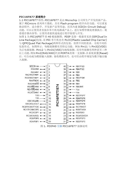
如图1为PIC16F877的40根接脚图,PDIP是指一般最常见的DIP(Dual In Line Package)包装,而PIC单片机也有PLCC(Plastic Leaded Chip Carrier)与QFP(Quad Flat Package)两种形式的包装,依照不同的需求,寻找不同的包装形式。
如图所示,每根接脚都有其特定功能,例如Pin11与Pin32(VDD)为正电源接脚,Pin12与Pin31(VSS)为地线接脚;而有些接脚有两种甚至三种以上功能,例如Pin2(RA0/AN0)代表PORTA的第一支接脚,在系统重置(Reset)后,可自动成为模拟输入接脚,接收模拟讯号,也可经由程序规划为数字输出输入接脚。
图1. PDIP40引脚PIC16F877接脚说明图2. PDIP28和SOIC28引脚PIC16F877接脚图说明图3. PLCC44引脚PIC16F877脚位图说明图4. QFP44引脚PIC16F877引脚图说明PIC16F877属于闪控式(Flash)单片机,可以重复烧录,其ROM的容量总共是8K words,以2K为一个page,区分为4个pages;内部RAM总共有512个字节(00f~1FFh),以128个字节为一个Bank,共区分为4个Bank,如图5所示,每个Bank的前半段都有其特殊用途,分别连接到其特殊功能模块,例如I/O、CCP、Timer、USART、MSSP等。
MikroElektronika PIC18FK 4K 系列开发板说明书
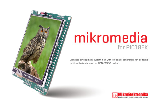
Compact development system rich with on-board peripherals for all-round multimedia development on PIC18F67K40 device.for PIC18FKmikromediaNebojsa MaticGeneral ManagerThe PIC®, dsPIC®, PIC24®, PIC32® and Windows® logos and product names are trademarks of Microchip Technology® and Microsoft® in the U.S.A. and other countries.Introduction to mikromedia for PIC18FK4 Package Contains 5 Key Features 6 System Specification 7 1. Power supply 8Battery power supply 8 USB power supply 8 2. PIC18F67K40 microcontroller 9Key microcontroller features 9 3. Programming the microcontroller 10 Programming with mikroBootloader 11 step 1 – Connecting mikromedia 11 step 2 – Browsing for .HEX file 12 step 3 – Selecting .HEX file 12 step 4 – Uploading .HEX file 13 step 5 – Finish upload 14 Programing with mikroProg programmer15 mikroProg Suite for PIC® Software 16 Programing with ICD2® or ICD3® programmer 174. Reset Button 185. microSD Card Slot 196. Crystal oscillator 207. Audio Module 218. Touch Screen 229. Accelerometer 2310. USB connection 2411. Flash Memory 2512. Pinouts 2613. Dimensions 2714. Schematic 2815. Mikromedia accessories 32 What’s next? 33Table of Contentsit convenient platform for mobile devices.0916010203040506070809101112131415Connection Pads TFT 320x240 display Micro USB connector CHARGE indication LED LI-Polymer battery connector 3.5mm headphone connector Power supply regulator Serial Flash memory RESET buttonVS1053 Stereo mp3 coder/decoder PIC18F87J50 microcontroller Accelerometer Crystal oscillator Power indication LED microSD Card Slot ICD2/3 connector mikroProg connector170306070811101213141516040517System Specificationpower supplyVia USB cable (5V DC)board dimensions81.2 x 60.5 mm (3.19 x 2.38 inch)weight~45.5g (0.10lbs)power consumption52 mA with erased MCU (when back-light is ON)CAUTION: Electrostatic Sensitive DevicePermanent damage may occur on devices subjected to high energy electrostatic discharges which readily accumulate on the human body or test equipment and can discharge without detection.class B productProduct complies with the Class B limit of EN 55022 and can be used in the domestic, residential, commercial and industrial environments.USB power supply - You can apply power supply to the board using micro USB cable provided with the board. On-board voltage regulators provide the appropriate voltage levels to each component on the board. Power LED (green) will indicate the presence of power supply.You can also power the board using Li-Polymer battery, via on-board battery connector. On-board battery charger circuit MCP73832 enables you to charge the battery over USB connection. LED diode (RED) will indicate when battery is charging. Charging current is ~250mA and charging voltage is 4.2V DC.Battery power supplyUSB power supplyFigure 1-1: Connecting USB power supplyFigure 1-2: Connecting Li-Polymer batteryKey MCU features- 128K bytes Program Flash - 3568 Bytes Data SRAM - 1024 Bytes Data EEPROMSleep mode: Lowest Power ConsumptionPIC18F67K40 is a 64-Pin, low-power, high performance microcontroller with XLP technology. equipped with a 10-bit ADC with Computation (ADCC) automating Capacitive Voltage Divider (CVD) techniques for advanced touch sensing, averaging, filtering, oversampling and performing automatic threshold comparisons.The microcontroller can be programmed in three ways:01 02 03Via USB UART mikroBootloader Using mikroProg external programmer Using ICD2/3® external programmerPIC18F67K40 microcontrollerYou can program the microcontroller with a bootloader which is preprogrammed by default. To transfer .hex file from a PC to MCU you need bootloader software (mikroBootloader USB HID) which can be downloaded from:Figure 3-2: mikroBootloader windowstep 1 – Connecting clicker 2 for PIC18FK01To start, connect the USB cable, or if already connected pressthe Reset button on your clicker 2 for PIC18FK. Click the Connect button within 5s to enter the bootloader mode, otherwise existingmicrocontroller program will execute.After the mikroBootloader software is downloaded, unzip it to desired location and start it.https:///examples/starter-boards/clicker-2/pic18fk/clicker-2-pic18fk-mikrobootloader-v100.zipclicker 2 for PIC18FK Bootloader WinRAR ZIP archiveclicker 2 for PIC18FK Bootloader File folderSoftware File foldermikroBootloader USB.exeBootloader tool for mikroElektron...mikroElektronikaPIC18F67K40_Bootloader_Firmware_v100.hex HEX FileFirmware File folder01step 3 – Selecting .HEX filestep 2 – Browsing for .HEX file Figure 3-3: Browse for HEXFigure 3-4: Selecting HEX0101020101Click the Browse for HEX button and from apop-up window (Figure 3-4) choose the .HEX file which will be uploaded to MCU memory.Select .HEX file using open dialog window.Click the Open button.step 4 – Uploading .HEX fileFigure 3-5: Begin uploadingFigure 3-6: Progress bar010101To start .HEX file bootloading click theBegin uploading button.Progress bar enables you to monitor .HEX file uploading.step 5 – Finish uploadFigure 3-7: Restarting MCU Figure 3-8: mikroBootloader ready for next job010102Click OK button after the uploading process is finished.Press Reset button on clicker 2 for PIC18FK board and waitfor 5 seconds. Your program will run automatically.The microcontroller can be programmed with mikroProg programmer and mikroProg Suite for PIC ® software. The mikroProg programmer is connected to the development system via the CN6 connector, Figure 3-9.mikroProg is a fast USB 2.0 programmer with mikroICD ™ hardware In-Circuit Debugger. Smart engineering allows mikroProg ™ to support PIC10®, PIC12®, PIC16®, PIC18®, dsPIC30/33®, PIC24® and PIC32® devices in a single programmer. It supports over 570 microcontrollers from Microchip ®. Outstanding performance, easy operation and elegant design are it’s key features.Programing with mikroProg programmerFigure 3-9:Connecting mikroProg to mikromediaspecial programming softwarecalled mikroProg Suite for PIC. Thissoftware is used for programmingof ALL Microchip® microcontrollerfamilies, including PIC10®, PIC12®,PIC16®, PIC18®, dsPIC30/33®, PIC24®and PIC32®. Software has intuitiveinterface and SingleClick™ programmingtechnology. Just by downloading thelatest version of mikroProg Suite yourprogrammer is ready to program newdevices. mikroProg Suite is updatedregularly, at least four times a year, soyour programmer will be more and morepowerful with each new release.Figure 3-10: Main window of mikroProg Suite for PIC® programming softwarePrograming with ICD2® or ICD3® programmerThe microcontroller can be also programmedwith ICD2® or ICD3® programmer. Theseprogrammers connects with mikromediaboard via ICD2 CONNECTOR BOARD.In order to enable the ICD2® and ICD3®programmers to be connected to thedevelopment system, it is necessary to providethe appropriate connector such as the ICD2CONNECTOR BOARD. This connector should befirst soldered on the CN5 connector. Then youshould plug the ICD2® or ICD3® programmerinto it, Figure 3-11.Figure 3-11:Connecting ICD2®or ICD3® programmerBoard is equipped with reset button, which is located at the top of the front side (Figure 4-2). If you want to reset the circuit, press the reset button. It will generate low voltage level on microcontroller reset pin (input). In addition, a reset can be externally provided through pin 27 on side headers(Figure 4-3).Figure 4-2: Frontal reset buttonFigure 4-1: Location of additional reset buttonFigure 4-1.5. microSD Card SlotFigure 6-1: microSD card slotBoard contains microSD card slot for using microSD cards in yourprojects. It enables you to store large amounts of data externally, thus savingmicrocontroller memory. microSD cards use Serial Peripheral Interface (SPI) forcommunication with the microcontroller.Figure 5-1:Crystal oscillator moduleBoard is equipped with 16MHz crystal oscillator (Y1) circuitthat provides external clock waveform to the microcontrollerCLKO and CLKI pins. This base frequency is suitable for further clockmultipliers and ideal for generation of necessary USB clock, which ensuresproper operation of bootloader and your custom USB-based applications.The use of crystal in all other schematics is implied even if it is purposely left out, because of the schematics clarity.Figure 8-2: 3.5mm headphones jackThe development system features a TFT 320x240 displaycovered with a resistive touch panel. Together they form afunctional unit called a touch screen. It enables data to beentered and displayed at the same time. The TFT display iscapable of showing graphics in 262.144 diffe r ent colors. Figure 7-1: Touch ScreenOn board ADXL345 accelerometer is used to measure accelerationin three axis: x, y and z. The accelerometer function is defined by theuser in the program loaded into the microcontroller. Communicationbetween the accelerometer and the microcontroller is performed viathe I2C interface.You can set the accelerometer address to 0 or 1 by re-soldering the SMDjumper (zero-ohm resistor) to the appropriate position. Jumper is placed inaddress 1 position by default.10. USB connectionFigure 9-1: ConnectingUSB cable to Micro USBconnectorPIC18F67K40 microcontroller has an integrated USB module, which enables you toimplement USB communication functionality to your mikromedia board. Connection withtarget USB host is done over micro USB connector which is positioned next to the battery connector.Figure 11-1: Flash memory moduleSince multimedia applications are getting increasingly demanding, it is necessary to provide additional memory spaceto be used for storing more data. The flash memory module enables the microcontroller to use additional 8Mbit flash memory. It is connected to the microcontroller via the Serial Peripheral Interface (SPI).VSYS RST GND GND RA0L RA1R RA2RC2RB4RC6RA4RC7RA5RG6RF0RA3RB0RB5RB1RB6RB2RB7RB3RH0RE0RH1RE1RD1RE2RD2RE3RD3RE4RD4RE5RA6RE6RA7RE7RG2RC3RG7RC4RD6RC5RD53.3V 3.3V GNDGNDSPI LinesInterrupt Lines Analog Lines Digital linesI2C Lines UART lines PWM lines81.1560.45 1.6 47144080LegendVCC-3V3R2610kC17100n0203BatteryBoost shieldPROTO shield0607Li-Polymer batteryWire Jumpers05mikroBUS shieldYou still don’t have an appropriate compiler? Locate PIC ® compiler that suits you best on our site:Choose between mikroC, mikroBasic and mikroPascal and download fully functional demo version, so you can begin building your first applications.Once you have chosen your compiler, and since you already got the board, you are ready to start writing your first projects. Visual TFT software for rapid development of graphical user interfaces enables you to quickly create your GUI. It will automatically create necessary code which is compatible with mikroElektronika compilers. Visual TFT is rich with examples, which are an excellent starting point for your future projects. Just load the example, read well commented code, and see how it works on hardware. Visual TFT is also available on our site:You have now completed the journey through each and every feature of mikromedia for PIC18FK board. You got to know it’s modules and organization. Now you are ready to start using your new board. We are suggesting several steps which are probably the best way to begin. We invite you to join the users of mikromedia ™ brand. You will find very useful projects and tutorials and can get help from a large ecosystem of users. Welcome!CompilerProjectsIf you want to learn more about our products, please visit our web site at If you are experiencing some problems with any of our products or just need additional information, please place your ticket at /supportIf you have any questions, comments or business proposals,do not hesitate to contact us at *****************。
- 1、下载文档前请自行甄别文档内容的完整性,平台不提供额外的编辑、内容补充、找答案等附加服务。
- 2、"仅部分预览"的文档,不可在线预览部分如存在完整性等问题,可反馈申请退款(可完整预览的文档不适用该条件!)。
- 3、如文档侵犯您的权益,请联系客服反馈,我们会尽快为您处理(人工客服工作时间:9:00-18:30)。
PIC18F87K22系列与XLP 8位开发板主要特性及相关图形类别:电子综合MICROCHIP公司的PIC18F87K22系列是采用极低功耗(nanoWatt XLP)技术的高性能MCU,集成了1Mb增强性闪存和24路12位ADC,具有高达16MIPS性能,8x8单周期硬件乘法器,工作频率高达64MHz,工作电压1.8V-5.5V,有10个CCP/ECCP 模块,11个8/16位定时器/计数器模块,两个主同步串口模块,特别适用于功率有严格要求和以电池为能源的应用.本文介绍了PIC18F87K22低功耗特性,MCU特性以及外设特性, 方框图以及XLP 8位开发板主要特性,主要元件及分布图以及电路图.PIC18F87K22 Family 64/80-Pin, High-Performance, 1-Mbit Enhanced Flash Microcontrollers with 12-Bit A/D and nanoWatt XLP TECHNOLOGYThis document contains device-specific information for the following DEVICES:This family combines the traditional advantages of all PIC18 microcontrollers –namely, high computational performance and a rich feature set – with an extremely competitive price point. These features make the PIC18F87K22 family a logical choice for many high-performance applications where price is a primary consideration.PIC18F87K22低功耗特性:Power-Managed modes:- Run: CPU on, peripherals on- Idle: CPU off, peripherals on- Sleep: CPU off, peripherals offTwo-Speed Oscillator Start-upFail-Safe Clock MONITORPower-Saving Peripheral MODULE Disable (PMD)Ultra Low-Power Wake-upFast Wake-up, 1 us TypicalLow-Power WDT, 300 nA TypicalUltra Low 50 nA Input LeakageRun mode Currents Down to 5.5 uA, TypicalIdle mode Currents Down to 1.7 uA TypicalSleep mode Currents Down to Very Low 20 nA, TypicalRTCC Current Downs to Very Low 700 nA, TypicalPIC18F87K22 MCU特性:Operating VOLTAGE Range: 1.8V to 5.5VOn-Chip 3.3V REGULATOROperating Speed up to 64 MHzUp to 128 Kbytes On-Chip Flash PROGRAM MEMORYData EEPROM of 1,024 Bytes4K x 8 GENERAL Purpose Registers (SRAM)10,000 Erase/Write Cycle Flash Program Memory, MINIMUM1,000,000 Erase/write Cycle Data EEPROM Memory, TypicalFlash Retention: 40 Years, MinimumThree Internal Oscillators: LF-INTRC (31 kHz), MF-INTOSC (500 kHz) and HF-INTOSC(16 MHz)Self-Programmable under SOFTWARE ControlPriority Levels for Interrupts8 x 8 Single-Cycle HARDWARE MultiplierExtended Watchdog Timer (WDT):- Programmable period from 4 ms to 4,194s (about 70 minutes)In-Circuit Serial PROGRAMMING (ICSP) via Two PinsIn-Circuit Debug via Two PinsProgrammable:- BOR- LVDPIC18F87K22外设亮点:Up to Ten CCP/ECCP MODULES:- Up to seven Capture/Compare/PWM (CCP) modules- Three Enhanced Capture/Compare/PWM (ECCP) modulesUp to Eleven 8/16-Bit Timer/Counter modules:- Timer0 – 8/16-bit timer/counter with 8-bit programmable prescaler- Timer1,3 – 16-bit timer/counter- Timer2,4,6,8 – 8-bit timer/counter- Timer5,7 – 16-bit timer/counter for 64k and 128k parts- Timer10,12 – 8-bit timer/counter for 64k and 128k partsThree ANALOG ComparatorsConfigurable Reference Clock OUTPUTHardware Real-Time Clock and Calendar (RTCC) module with Clock, Calendar and Alarm FunctionsCharge Time Measurement Unit (CTMU):- Capacitance measurement for mTouch sensing solution- Time measurement with 1 ns typical resolution- INTEGRATED temperature sensorHigh-Current Sink/Source 25 mA/25 mA (PORTB and PORTC)Up to Four External InterruptsTwo MASTER Synchronous Serial Port (MSSP) modules: - 3/4-wire SPI (supports all four SPI modes)- I2C Master and Slave modesTwo Enhanced Addressable USART modules:- LIN/J2602 support- Auto-Baud Detect (ABD)12-Bit A/D CONVERTER with up to 24 Channels:- Auto-acquisition and Sleep operation- Differential input mode of operationIntegrated Voltage Reference图1.PIC18F6XK22 (64引脚)方框图XLP 8位开发板The board provides a low-cost, highly configurable development SYSTEM for Microchip’s new line of 64 and 80-pin Extreme Low-Power (XLP) microcontrollers, including the PIC16(L)F1947 and PIC18F87K22 families.The XLP 8-bit board permits users to explore and EVALUATE extreme low-power features, and learn low-power software and hardware techniques. Various headers are available to measure the power consumption of both the microcontroller and development board. It is flexible, supporting five different power sources over a wide voltage range. It is highly configurable, equipped with a variety of COMMONperipheral COMPONENTS that can be selectively enabled. Finally, it is expandable through its MODULAR INTERFACE, providing for the addition of ADVANCED interfaces and connectivity methods.As provided, the XLP 8-Bit Development Board functions as a demonstration platform on initial power-up. The included demonstration software takes a temperature measurement, datalogs information to the serial data EEPROM, and displays information to the on-board LCD. Additional software is provided to demonstrate low-power techniques and IC interface routines.XLP 8位开发板主要特性:The XLP 8-Bit Development Board includes these features:Support for both 64-pin and 80-pin versions of both PIC16 (L)F-series and PIC18 K-series Flash microcontrollers via Plug-In Modules (PIMs)Built-in capability for separately measuring microcontroller and board current consumptionMultiple oscillator optionsAccommodations for five different power source optionsConfigurability for a wide range of operating voltages (1.8V to 3.3V)Configuration selection JUMPERS to disable board componentsA hardware switchable option to control power to board components with port pinThree push buttonsSeven LEDsPotentiometer for analog input16x2 character LCD with controllerSerial EEPROM storagePICtail interface for connection to various application daughter BOARDSSerial Accessory Port (SAP)Temperature sensorPrototyping AreaSupport for all Microchip compatible programmers and emulatorsXLP 8位开发板包括:The XLP 8-Bit Development Board includes the following:XLP 8-Bit Development BoardPIC16(L)F1947 Plug-In ModulePIC18F87K22 Plug-In ModuleUSB mini-B cablePower Analyzer cable图2. XLP 8位开发板元件分布图XLP 8位开发板所对应元件如下:The board includes these specific features, as indicated in the diagram:1. CONNECTOR for Plug-In Modules (PIM)2. Oscillator circuits (10 MHz and 32.768 kHz) for microcontroller on PIM3. Power supply area (BATTERY holders, external power supply input, LDO regulator and power supply select jumper) interface headers for the energy harvester demonstration board4. Power LED5. LDO regulator6. IC power-select jumpers7. Microcontroller Master Clear switch8. Push buttons9. Potentiometer10. LEDs11. 2x16 character LCD12. Serial EEPROM13. Temperature sensor14. PICkit? programmer/debugger 6-pin interface15. Modular 28-pin riser interface for daughter boards16. Serial Accessory Port17. Prototype area with supply voltage and I2C? signal access18. Current measurement jumpers and access point图3.PIC16LF1947 PIM BREAKOUT图4. XLP 8位开发板电路图(1)图5. XLP 8位开发板电路图(2)。