D571-10F中文资料
水轮机进水重锤式液压控制蝶阀产品使用说明书
水轮机进水重锤式液压控制蝶阀产品使用说明书 The following text is amended on 12 November 2020.一、主要性能特点、用途及适用范围本产品为新型的水轮机进水重锤式液压控制蝶阀,全称为希斯威系列水轮机进水重锤式液控蝶阀或希斯威系列水电站开阀锁定型自动保压重锤式液控止回蝶阀,分普通型和防泥沙型两种,防泥沙型液控蝶阀用于水中含泥沙等杂质较多的水电站工程。
希斯威系列液控蝶阀开启采用液压驱动,油压可达16Mpa,减少了接力器的体积,开启过程中,同时将一重锤举起,利用举起的重锤蓄能关闭,取消蓄能罐,开启后锁锭自动投入,液压系统自动保压,重锤不下掉,蝶板不抖动。
关闭时不需动力油源,自动解除锁锭销、按预定的程序关闭,简单可靠,大大简化了液压系统。
采用双偏心阀板,水平安装的阀轴在管道中心线上抬高一定距离,使阀板下半部迎水面积大于上半部,能利用动水力的作用帮助阀门关闭以减小重锤的重量,将结构简单、体积小的油压装置、蝴蝶阀控制柜、电气自动控制箱、接力器、控制油管很紧凑的与阀门集聚在一起,不需用户另外配置。
该阀能实现就地控制、远方控制及联动控制,可满足“无人值班、少人值守”的要求,是一种理想的新型管路控制设备。
这种液控蝶阀是水电站中管线系统截断或接通介质的理想设备,适用于装在水轮机前的压力钢管处,作为水轮机进水阀,其作用为:1、水轮机发生事故且导叶不能关闭时,动水关闭阀门,紧急关闭截断水流,防止水轮机发生飞逸,确保机组安全。
2、机组停机备用时,关闭阀门,截断水流,防止水轮导叶长期漏水,既减少水能损失,又可防止在导叶端面和立面处产生间隙气蚀。
3、机组停机检修时,静水关闭阀门,截断水流。
本蝶阀还适用于高位布置在压力钢管的始端,用作压力钢管保护阀,在压力钢管发生爆裂等情况时紧急关闭截断水流,防止事故扩大,确保安全。
本系列蝶阀的驱动装置可根据厂房的需要设计在水流方向的左边或右边,重锤可根据电站需要而设计成倒向顺水流方向或逆水流方向。
571分析仪说明书-9页精选文档

1概述1.1仪器的主要特点1.2仪器的正常工作条件1.3型号编制1.4安全2结构特征2.1仪器的外形图2.2仪器的操作面板图2.3仪器的后视图2.4仪器的侧面图3技术特性4尺寸、重量5开箱及检查6安装7使用步骤7.1反应管预处理及密封圈和隔膜装配7.2样品准备工作7.3消解操作步骤7.4测量准备7.5低浓度COD的测量7.6高浓度COD的测量7.7废液处理7.8测量结束工作8仪器的日常维护附录一COD标准溶液的配制方法附录二专用氧化剂A或B的配制方法附录三重蒸馏水的制备方法1 概述化学需氧量(Chemical Oxygen Demand,简称COD)是在一定条件下,用强氧化剂处理水样时所消耗氧化剂的量,结果一般以氧的量来表示(以mg/L计),反映了水受还原性物质污染的程度。
通常情况下,还原性物质主要是有机物,因此,化学需氧量也是作为有机物相对含量的指标之一。
化学需氧量测定方法通常是重铬酸钾法或高锰酸钾法。
欧美多采用重铬酸钾法,日本则广泛采用高锰酸钾法,我国根据自己的国情规定了用重铬酸钾法测定化学需氧量。
COD-571型化学需氧量分析仪是采用比色法测定化学需氧量的实验室仪器。
参照了我国有关化学需氧量的测定方法,我们专门设计了与分析仪配套的消解装置,可同时进行21个样品加热回流仪器,具有体积小,操作方便,节约大量水、电及试剂,减少二次污染等优点,主要适用于焦化、造纸、石化、印染、皮毛、制革、制药、试剂、食品加工等工业废水中化学需氧量的测定。
1.1仪器的主要特点1.采用单片机技术,中文菜单显示操作简单明了。
2.COD分析仪可直接读取COD结果,无需滴定等其它方法进行分析。
3.采用PP40打印机,可将结果打印输出。
1.2仪器的正常工作条件1.环境温度:(5~35)℃;2.相对湿度:不大于85%;3.供电电源:AC(220±22)V,频率(50±0.5)Hz;4.周围空气中无腐蚀性的气体存在;5.周围无影响性能的振动存在;6.周围除地磁场外无其它影响性能的电磁场干扰。
流量计

上海迪华科技有限公司
中华人民共和国计量器具制造许可
DTFX1020 系列超声流量计用户手册
目录
第一章 概述......................................................................................................................................................... 1
第三章 变送器的安装、接线及面板操作 ......................................................................................................... 8
§3.1 变送器的安装选点 .................................................................................................................................. 8 §3.2 DTFX1020 变送器外形尺寸图和接线..................................................................................................... 8
§1.1 引言 ............................................................................................................................................................ 1 §1.2 DTFX1020 的工作原理........................................................................................................................... 1 §1.3 DTFX1020 的典型用途 ............................................................................................................................ 2 §1.4 DTFX1020 的主要技术特点 .................................................................................................................... 2 §1.5 主要技术参数.......................................................................................................................................... 3
松下DH57系列说明最终版

Panasonic Information Systems Co., Ltd.
パナソニック インフォメーションシステム
Panasonic 末端紧固绝缘子安装说明
4
Panasonic Information Systems Co., Ltd.
パナソニック インフォメーションシステム
Panasonic 末端紧固绝缘子安装说明
5
Panasonic Information Systems Co., Ltd.
パナソニック インフォメーションシステム
100m~150m
连接件
非标准品的安装说明及注意事项: 1,当距离在100~150米之间的时候,需要 使用特注的末端紧固绝缘子,确保产品能够 正常运行。 2,吊夹的间隔距离为1.5M以下
Panasonic Information Systems Co., Ltd.
パナソニック インフォメーションシステム
パナソニック インフォメーションシステム
Panasonic 本体安装说明
3
安装说明及注意事项: 1,将本体放置在场地中抽出。切勿将本体竖 立起推着走,否则很容易将树脂片弄断裂(附 图:因将竖立推着拉出,导致树脂片断裂)
Panasonic Information Systems Co., Ltd.
パナソニック インフォメーションシステム
11
Panasonic Information Systems Co., Ltd.
パナソニック インフォメーションシステム
Panasonic 连接件,馈电连接件及吊夹安装说明
12
中间馈点连接件的安装说明及注意事项: 1,需要将本体间的树脂片锉去垂直距离 为4~5MM,横向距离为≈30MM 2,需将铜体弯折为90° 3,使端子紧贴连接体本体,不能留出空 隙 4,端子S与端子L需按照图纸正确安装 5,注:中间馈电连接件的电线拉出口侧 需要放置吊夹,距离为450~550MM。 另一侧的距离为550MM~750MM
5713中文资料
lOFF
VON
ILK VD lCC(1) lCC(0)
— — — — NOM NOM NOM NOM
MIN OPEN
MIN MIN NOM NOM MAX MAX
2.0 V 2.0 V 0.8 V 0.8 V 0V VCC 5.0 V 0V
0V
80 V
—
0V
80 V
—
0.8 V 150 mA —
0.8 V 300 mA —
Suppression Diode On-State Current,
I O ION . . . . . . . . . . . . . . . . . . . . . . 600 mA D F Power Dissipation at TA = 25°C, PD
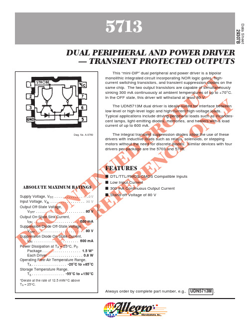
FEATURES
s DTL/TTL/PMOS/CMOS Compatible Inputs s Low Input Current s 300 mA Continuous Output Current s Stand-off Voltage of 80 V
Storage Temperature Range,
TS . . . . . . . . . . . . . . . . -55°C to +150°C
*Derate at the rate of 12.5 mW/°C above TA = 25°C.
Always order by complete part number, e.g., UDN5713M .
—
— -50 -100 µA
2
IIN(0)
—
MAX 0.4 V 30 V
—
— -100 -200 µA —
茨浮变频器

◆可选配GPRS远程通讯模块实现远程控制与操作,便于工程商、代理商、最终用户的使用和维护。
该系列产品根据用途可分为通用型和多种专用型产品。
内置多项自主专有技术的模组,具有节能负载跟踪能力,可在50HZ的频率下实现节能运行。采用美国TI公司 32BIT DSP控制,驱动电路采用美国高可靠专用驱动保护模块、双重光电隔离、光纤传输、内置智能PID调节器、 内置485串行通讯接口,及标准modbus工业现场总线协议;SC总线协议。设有风机自动控制电路,根据环境温度和 散热片温度自动控制风机的启动停止和速度,从而延长了风机的寿命。该产品还具有参数拷贝功能,可以通过键 盘或远程拷贝或设置功能参数。可选配GPRS远程通讯模块。实现变频器的远程控制和参数设置。可实现油田抽油 机的监控和电流工图传输和显示。可靠性高、EMI低,使用寿命长,结构紧凑合理、体积小、便于安装、可柜内安 装。
(High Voltage Inverters)
是带能量回馈的四象限运行的三电平直接转矩控制的中压变频器(690V~10kV,100~1000kHP),带有PWM整 流,可使输入功率因数接近于1。机械特性硬度高。零速可达150%的转矩。适用于中压起重机械、牵引、轧制机 械等对速度、转矩有高精度要求的场合。
·PWM整流单元
·PWM回馈单元
·APFC模块
·直流制动单元
·GPRS通讯模块
·输入电抗器
·输入EMI滤波器
(High Voltage Inverter)
是完美无谐波中压变频器(2.3~13.8kV,300~10000KW)可提供无与伦比的高可靠性及效率。该产品采用我 所自主研发的MASTDRIVE作为控制器。控制器功能齐全,算法独特,运算精确,波形质量高。在节能方面更是独 树一帜。完美无谐波变频器在电压和电流谐波方面能够满足要求最为严格的IEEE519标准。选择完美无谐波中压 变频器,无论是何种工业、何种应用都意味着保持高产量的同时降低维护成本,改进节能工艺的同时降低运营成 本。为了验证和测试控制波形的正确性,我们研制成功了在线单元串联高压变频器计算机仿真系统平台,在这个 平台上可以验证各种控制算法的正确性和控制性能。
D571中文资料

Advance Data Sheet April 2000D571-Type Digital 1.5 µ m Uncooled DFBFastLight ™ Laser ModuleThe low-profile D571-Type Laser Module is ideally suited for L u c e n t D 571-10A S /N -L 651036 s Hermetically sealed active components s Internal back-facet monitorsQualification program: Telcordia Technologies * TA-983* Telcordia Technologies is a trademark of Bell Communications Research, Inc.ApplicationssLong-reach SONET OC-3/STM-1, OC-12/STM-4 systemss Telecommunications sSecure digital data systemsBenefitss Easily board mounted s Requires no lead bending s No additional heat sinks requiredsPin compatible with industry-standard 14-pin laser modulesHighly efficient DFB-MQW laser structure allows for lower threshold and drive currents, and reduced power consumptionDescriptionThe D571-Type Uncooled Laser Module consists of a laser diode coupled to a single-mode fiber pigtail. The device is available in a standard, 8-pin configu-ration (see Figure 1 and/or Table 1) and is ideal for long-reach (SONET) and other high-speed digital applications.The laser diode is a narrow linewidth (<1 nm) DFB-MQW single-mode laser and an InGaAs PIN photo-diode back-facet monitor in an epoxy-free, hermeti-cally sealed package.元器件交易网D571-Type Digital 1.5 µ m Uncooled DFB Advance Data SheetFastLight Laser ModuleApril 20002Lucent Technologies Inc.Description (continued)The device characteristics listed in this document are met at 2.0 mW output power. Higher- or lower-power operation is possible. Under conditions of a fixed pho-todiode current, the change in optical output is typically ± 0.5 dB over an operating temperature range of –40 ° C to +85 ° C.This device incorporates the new Laser 2000 manufac-turing process developed by the Optoelectronic unit of Lucent Technologies Microelectronics Group. Laser 2000 is a low-cost platform that targets high-volume manufacturing and tighter product distributions on all optical subassemblies. The platform incorporates an advanced optical design that is produced on a highly automated production line. The Laser 2000 platform isqualified for the central office and uncontrolled environ-ments, and can be used for applications requiring high performance and low cost. Table 1. Pin DescriptionsPin NumberConnection 1NC/Reserved 2Case ground 3NC/Reserved 4Photodiode cathode 5Photodiode anode 6Laser diode cathode 7Laser diode anode 8NC/ReservedFigure 1. D571-Type Digital Uncooled DFB Flat-PAC Laser Module Schematic, Top ViewAbsolute Maximum RatingsStresses in excess of the absolute maximum ratings can cause permanent damage to the device. These are abso-lute stress ratings only. Functional operation of the device is not implied at these or any other conditions in excess of those given in the operations sections of the data sheet. Exposure to absolute maximum ratings for extended periods can adversely affect device reliability.* Rating varies with temperature.ParameterSymbol Min Max Unit Maximum Peak Laser Drive Current or Maximum Fiber Power* I OP P MAX ——15010mA mW Peak Reverse Laser Voltage:Laser MonitorV RL V RM ——220V V Monitor Forward CurrentI FD —2mA Operating Case Temperature Range T C–4085 ° C Storage Case Temperature Range T stg –4085 ° C Lead Soldering Temperature/Time — —260/10 °C/s Relative Humidity (noncondensing)RH—85%1-900 (C)元器件交易网元器件交易网Advance Data Sheet D571-Type Digital 1.5 µm Uncooled DFBApril 2000FastLight Laser ModuleD571-Type Digital 1.5 µm Uncooled DFB Advance Data Sheet FastLight Laser Module April 20000.17(4.32)元器件交易网Advance Data Sheet D571-Type Digital 1.5 µm Uncooled DFBApril 2000FastLight Laser ModuleD571-Type Digital 1.5 µm Uncooled DFB Advance Data Sheet FastLight Laser Module April 200010 mW 1.5 µmAdvance Data Sheet D571-Type Digital 1.5 µm Uncooled DFB April 2000FastLight Laser ModuleFor additional information, contact your Microelectronics Group Account Manager or the following:INTERNET:/micro, or for Optoelectronics information, /micro/optoE-MAIL:docmaster@N. AMERICA:Microelectronics Group, Lucent Technologies Inc., 555 Union Boulevard, Room 30L-15P-BA, Allentown, P A 181031-800-372-2447, FAX 610-712-4106 (In CANADA: 1-800-553-2448, FAX 610-712-4106)ASIA PACIFIC:Microelectronics Group, Lucent Technologies Singapore Pte. Ltd., 77 Science Park Drive, #03-18 Cintech III, Singapore 118256 Tel. (65) 778 8833, FAX (65) 777 7495CHINA:Microelectronics Group, Lucent Technologies (China) Co., Ltd., A-F2, 23/F, Zao Fong Universe Building, 1800 Zhong Shan Xi Road, Shanghai 200233 P. R. China Tel. (86) 21 6440 0468, ext. 316, FAX (86) 21 6440 0652JAP AN:Microelectronics Group, Lucent Technologies Japan Ltd., 7-18, Higashi-Gotanda 2-chome, Shinagawa-ku, Tokyo 141, Japan Tel. (81) 3 5421 1600, FAX (81) 3 5421 1700EUROPE:Data Requests: MICROELECTRONICS GROUP DATALINE: Tel. (44) 7000 582 368, FAX (44) 1189 328 148Technical Inquiries:OPTOELECTRONICS MARKETING: (44) 1344 865 900 (Ascot UK)Lucent Technologies Inc. reserves the right to make changes to the product(s) or information contained herein without notice. No liability is assumed as a result of their use or application. No rights under any patent accompany the sale of any such product(s) or information. FastLight is a trademark of Lucent Technologies Inc.Copyright © 2000 Lucent Technologies Inc.All Rights ReservedApril 2000DS00-136OPTO (Replaces DS99-056LWP)。
Yokogawa DL系列差分探测器(Model 700924)用户手册说明书
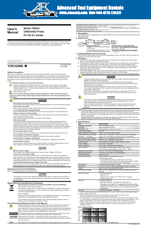
User's ManualThank you for purchasing the Differential Probe (Model 700924) for the DL series. To ensure correct use, please read this manual thoroughly before beginning operation. After reading the manual, keep it in a convenient location for quick reference whenever a question arises during operation.IM 700924-01E IM 700924-01EModel 700924Differential Probe for the DL SeriesYOKOGAWA ELECTRIC CORPORATION, Communication & Measurement Business Headquarters Phone: (81)-422-52-67689-32, Nakacho 2-chome, Musashino-shi, Tokyo, 180-8750 JAPANYOKOGAWA CORPORATION OF AMERICA Phone: (1)-770-253-70002 Dart Road, Newnan, Ga. 30265-1094, U.S.A.YOKOGAWA EUROPE B.V. Phone: (31)-33-4641858Databankweg 20, 3821 AL, Amersfoort, THE NETHERLANDS YOKOGAWA ENGINEERING ASIA PTE. LTD. Phone: (65)-624199335 Bedok South Road, Singapore 469270, SINGAPORE7th Edition7th Edition : October 2007 (YK)All Rights Reserved, Copyright © 2007, Yokogawa Electric CorporationSafety PrecautionsMake sure to comply with the safety precautions mentioned hereafter when handling the probe.Yokogawa Electric Corporation assumes no responsibility for any consequences resulting from failure to comply with these safety precautions. Also, read the User’s Manual of the measuring instrument thoroughly so that you are fully aware of its specifications and handling, before starting to use the probe.The following symbols are used on this instrument.Warning: handle with care. Refer to the user’s manual or service manual. This symbol appears on dangerous locations on the instrument which require special instructions forproper handling or use. The same symbol appears in the corresponding place in the manual to identify those instructions. Risk of electric shockMake sure to comply with the following safety precautions in order to prevent accidents such as an electric shock which impose serious health risks to the user and damage to theGrounding of the measuring instrumentThe protective grounding terminal of the measuring instrument must be connected to ground.Earth cable of the probeMake sure to connect the earth cable of the probe to the ground (grounding potential). Do not operated with suspected failuresIf you suspect that there is damage to this probe, have it inspect by a service personnel.Observe maximum working voltageTo avoid any injury,do not use the probe above 1400 Vpeak between each input lead and earth or between the two inputs.This voltage rating applies to both 1/100 and 1/1000 settings.Must be groundedThis probe must be grounded with the BNC shell and an auxiliary grounding terminal, through the grounding conductor of the power cord of the measuring instrument or other appropriate grounding conductor. Before making connections to the input terminals of the product, ensure that the output connector is attached to the BNC connector of the measuring instrument and the auxiliary grounding terminal is connected to a proper ground, while the measuring instrument is properly grounded.Do not operate without coverTo avoid electric shock or fire hazard, do not operate this probe with the cover removed.Do not operate in wet/damp conditionsTo avoid electric shock, do not operate this probe in wet or damp conditions.Do not operate in explosive atmosphereTo aviod injury or fire hazard, do not operate this probe in an explosive atmosphere.Avoid exposed circuitryTo avoid injury, remove jewelry such as rings, watches, and other metallic objects. Do not touch exposed connections and components when power is present.CAUTIONMaximum input voltageDo not apply any voltages exceeding the maximum input voltage to the probe.Correct use of the power supplyPower the probe with either 4 AA dry cells, a 6 VDC/200 mA or 9 VDC/150 mA externalpower supply, or by connecting the probe’s power cable to a probe power supply terminal on a DL series measuring instrument or to the 700938 or 701934. Operating the probe under a power supply greater than the voltage specified above may cause damage to the instrument. Connecting the external power supply to the probeAlways turn OFF the probe’s power switch when connecting or disconnecting the external power supply. Also, do not install the dry cells when using an external power supply.Operating environment limitationsSee below for operating environment limitations.CAUTIONThis product is a Class A (for industrial environments) product. Operation of this product in a residential area may cause radio interference in which case the user is required to correct the interference.Waste Electrical and Electronic Equipment (WEEE), Directive 2002/96/EC (This directive is only valid in the EU.)This product complies with the WEEE Directive (2002/96/EC) marking requirement. This marking indicates that you must not discard this electrical/electronic product in domestic household waste.Product CategoryWith reference to the equipment types in the WEEE directive Annex 1, this product is classified as a “Monitoring and Control instrumentation” product.Do not dispose in domestic household waste. When disposing products in the EU, contact your local Yokogawa Europe B. V. office.The Following Symbols are Used in this Manual.Improper handling or use can lead to injury to the user or damage to the instrument. This symbol appears on the instrument to indicate that the user must refer to theuser’s manual for special instructions. The same symbol appears in the corresponding place in the user’s manual to identify those instructions. In the manual, the symbol is used in conjunction with the word “WARNING” or “CAUTION.”WARNING Calls attention to actions or conditions that could cause serious or fatal injury to theuser, and precautions that can be taken to prevent such occurrences.CAUTION Calls attentions to actions or conditions that could cause light injury to the user ordamage to the instrument or user’s data, and precautions that can be taken to prevent such occurrences.NoteCalls attention to information that is important for proper operation of the instrument.1 DescriptionBy using this device, oscilloscopes with single-ended input can be easily used as oscilloscopes with differential inputs.2 Appearance22 Pinchers tips3 Ground extention lead (length = 100 cm)Power cable*Pinchers tip B9852MJ Black: B9852MM, Red: B9852MN* Power can be supplied from the DL, 700938,or 701934.Optional Accessories (Sold Separately)3 Installing/Replacing the Dry CellsShift the lid at the back side of the probe and install/replace the four dry cells. The dry cells are not installed on receipt of the instrument.4 Operation1. Install four AA cells. When using an external power supply, do not install the dry cells. Supply power only through the external power supply.2. Simply plug-in the BNC output connector to the vertical input of a oscilloscope, and connect the auxiliary grounding terminal to a proper ground. If necessary, use a ground extention lead.3. Select the proper range setting. For higher resolution and less noise when measuring signals below 350V, switch the attenuation to 1/100. Otherwise, set the attenuation to 1/1000 when measuring signals above 350V.4. If the offset voltage is large, short the top of input leads, and turn the ADJUST variable resistor (DC voltage adjustment) using a flat-head screwdriver to adjust the offset voltage.• To protect against electric shock the ground side of the output cable (the shielded side of the BNC connector) must be grounded.• Make sure to avoid an electric shock when connecting the probe to the object ofmeasurement. Do not remove the probe from the measuring instrument after the object of measurement is connected.• When disconnecting the probe BNC output connector, first turn OFF the power to the circuit under measurement. Then, disconnect the probe from the high voltage parts of the circuit under measurement.• When replacing batteries or connecting an external power supply, first turn OFF the power to the circuit under measurement. Then, remove the input lead from the circuit under measurement.CAUTION• This probe is to carry out differential measurement between two points on the circuit under measurement. This probe is not for electrically insulating the circuit under measurement and the measuring instrument.• Use a soft cloth to clean the dirt. Prevent damage to the probe. Avoid immersing the probe, using abrasive cleaners, and using chemicals contains benzene or similar solvents.Note• Connect the BNC connector to the input terminal of the oscilloscope and for two pointmeasurement (differential measurement), connect both input leads. Because the performance declines in case you carry out measurements with only one input lead connected, make sure to always connect both.• Accurate measurement may not be possible near objects with strong electric fields (such as cordless equipment, transformers, or circuits with large currents).5 SpecificationsItemSpecificationsFrequency bandwidth *1DC to 100 MHz (−3 dB)Input typeBalancing difference inputAttenuation ratioswitched ratios of 100:1 and 1000:1Output offset voltage *1 *2±7.5 mVInput resistance and capacity 4 M Ω + 10 pF each side to groundDifferential allowable voltage ±1400 V (DC + ACpeak) or 1000 Vrms at 1000:1 attenuation (between + − terminal)±350 V (DC + ACpeak) or 250 Vrms at 100:1 attenuation Max common mode voltage ±1400 V (DC + ACpeak) or 1000 Vrms Max input voltage(to ground)±1400 V (DC + ACpeak) or 1000 VrmsCMRR (typical)*160 Hz: less than −80 dB; 1 MHz: less than −50 dB Output voltage *1±3.5 V (DC + ACpeak)Output impedance Using 1 M Ω input system oscilloscopeGain accuracy *1±2% (common mode voltage ≤ 400 V and ≥ −400 V)±3% (common mode voltage ≤ 1000 V and ≥ −1000 V)Operating environment 5 to 40°C, 25 to 85% (no condensation)Storage environment −30 to 60°C, 25 to 85% (no condensation)Operating altitude 2,000 m or lessPower requirements *3Internal battery: four dry cells (AA, R6)External power supply:6 VDC/200 mA or more, or 9 VDC/150 mA or more.From the DL series instrument’s probe power supply, 700938, or 701934 using the probe’s power supply cable. Cell life time In continuous duty, approx. 2 hoursDimensions 207 mm × 83 mm × 38 mm (excluding connector and cable)WeightApprox. 800 g ( excluding the dry cells)Withstanding voltage 2000 VACrms (between input terminal and BNC-ground), for 5 minutesSafety standardsComplying standards EN61010-031Measurement category III *4: 1400 V (DC + ACpeak)Pollution degree 2*5EmissionComplying standardsEN61326, EN55011, EN61000-3-2, EN61000-3-3This product is a Class A (for industrial environment) product. Operation of this product in a residential area may cause radio interference in which case the user is required to correct the interference.ImmunityComplying standards EN61326*1 When the power supply voltage from the dry cells is 5 V or more, or when using an external power supply.*2 Ambient temperature 23±5°C*3 When the capacity of dry cells goes down LED blinks. In such a case, replace the dry cells. Also, do not install the dry cells when using an external power supply.*4This equipment is for measurement category III (CAT III). Do not use it with measurement category IV (CAT IV). CAT III applies to measurement of the distribution level, that is , building wiring, fixed installations. CAT IV applies to measurement of the primary supply level, that is, overhead lines, cable systems, and so on.*5 Pollution degree applies to the degree of adhesion of a solid, liquid, or gas which deteriorates withstandvoltage or surface resistivity. Pollution degree 2 applies to normal indoor atmospheres (with only non-conductive pollution).Input voltage deratingFrequency (Hz)0.1 M1010010001400 1 M 10 M 100 M M a x i n p u t v o l t a g e (V )1981。
- 1、下载文档前请自行甄别文档内容的完整性,平台不提供额外的编辑、内容补充、找答案等附加服务。
- 2、"仅部分预览"的文档,不可在线预览部分如存在完整性等问题,可反馈申请退款(可完整预览的文档不适用该条件!)。
- 3、如文档侵犯您的权益,请联系客服反馈,我们会尽快为您处理(人工客服工作时间:9:00-18:30)。
Advance Data Sheet April 2000D571-Type Digital 1.5 µ m Uncooled DFBFastLight ™ Laser ModuleThe low-profile D571-Type Laser Module is ideally suited for L u c e n t D 571-10A S /N -L 651036 s Hermetically sealed active components s Internal back-facet monitorsQualification program: Telcordia Technologies * TA-983* Telcordia Technologies is a trademark of Bell Communications Research, Inc.ApplicationssLong-reach SONET OC-3/STM-1, OC-12/STM-4 systemss Telecommunications sSecure digital data systemsBenefitss Easily board mounted s Requires no lead bending s No additional heat sinks requiredsPin compatible with industry-standard 14-pin laser modulesHighly efficient DFB-MQW laser structure allows for lower threshold and drive currents, and reduced power consumptionDescriptionThe D571-Type Uncooled Laser Module consists of a laser diode coupled to a single-mode fiber pigtail. The device is available in a standard, 8-pin configu-ration (see Figure 1 and/or Table 1) and is ideal for long-reach (SONET) and other high-speed digital applications.The laser diode is a narrow linewidth (<1 nm) DFB-MQW single-mode laser and an InGaAs PIN photo-diode back-facet monitor in an epoxy-free, hermeti-cally sealed package.元器件交易网D571-Type Digital 1.5 µ m Uncooled DFB Advance Data SheetFastLight Laser ModuleApril 20002Lucent Technologies Inc.Description (continued)The device characteristics listed in this document are met at 2.0 mW output power. Higher- or lower-power operation is possible. Under conditions of a fixed pho-todiode current, the change in optical output is typically ± 0.5 dB over an operating temperature range of –40 ° C to +85 ° C.This device incorporates the new Laser 2000 manufac-turing process developed by the Optoelectronic unit of Lucent Technologies Microelectronics Group. Laser 2000 is a low-cost platform that targets high-volume manufacturing and tighter product distributions on all optical subassemblies. The platform incorporates an advanced optical design that is produced on a highly automated production line. The Laser 2000 platform isqualified for the central office and uncontrolled environ-ments, and can be used for applications requiring high performance and low cost. Table 1. Pin DescriptionsPin NumberConnection 1NC/Reserved 2Case ground 3NC/Reserved 4Photodiode cathode 5Photodiode anode 6Laser diode cathode 7Laser diode anode 8NC/ReservedFigure 1. D571-Type Digital Uncooled DFB Flat-PAC Laser Module Schematic, Top ViewAbsolute Maximum RatingsStresses in excess of the absolute maximum ratings can cause permanent damage to the device. These are abso-lute stress ratings only. Functional operation of the device is not implied at these or any other conditions in excess of those given in the operations sections of the data sheet. Exposure to absolute maximum ratings for extended periods can adversely affect device reliability.* Rating varies with temperature.ParameterSymbol Min Max Unit Maximum Peak Laser Drive Current or Maximum Fiber Power* I OP P MAX ——15010mA mW Peak Reverse Laser Voltage:Laser MonitorV RL V RM ——220V V Monitor Forward CurrentI FD —2mA Operating Case Temperature Range T C–4085 ° C Storage Case Temperature Range T stg –4085 ° C Lead Soldering Temperature/Time — —260/10 °C/s Relative Humidity (noncondensing)RH—85%1-900 (C)元器件交易网元器件交易网Advance Data Sheet D571-Type Digital 1.5 µm Uncooled DFBApril 2000FastLight Laser ModuleD571-Type Digital 1.5 µm Uncooled DFB Advance Data Sheet FastLight Laser Module April 20000.17(4.32)元器件交易网Advance Data Sheet D571-Type Digital 1.5 µm Uncooled DFBApril 2000FastLight Laser ModuleD571-Type Digital 1.5 µm Uncooled DFB Advance Data Sheet FastLight Laser Module April 200010 mW 1.5 µmAdvance Data Sheet D571-Type Digital 1.5 µm Uncooled DFB April 2000FastLight Laser ModuleFor additional information, contact your Microelectronics Group Account Manager or the following:INTERNET:/micro, or for Optoelectronics information, /micro/optoE-MAIL:docmaster@N. AMERICA:Microelectronics Group, Lucent Technologies Inc., 555 Union Boulevard, Room 30L-15P-BA, Allentown, P A 181031-800-372-2447, FAX 610-712-4106 (In CANADA: 1-800-553-2448, FAX 610-712-4106)ASIA PACIFIC:Microelectronics Group, Lucent Technologies Singapore Pte. Ltd., 77 Science Park Drive, #03-18 Cintech III, Singapore 118256 Tel. (65) 778 8833, FAX (65) 777 7495CHINA:Microelectronics Group, Lucent Technologies (China) Co., Ltd., A-F2, 23/F, Zao Fong Universe Building, 1800 Zhong Shan Xi Road, Shanghai 200233 P. R. China Tel. (86) 21 6440 0468, ext. 316, FAX (86) 21 6440 0652JAP AN:Microelectronics Group, Lucent Technologies Japan Ltd., 7-18, Higashi-Gotanda 2-chome, Shinagawa-ku, Tokyo 141, Japan Tel. (81) 3 5421 1600, FAX (81) 3 5421 1700EUROPE:Data Requests: MICROELECTRONICS GROUP DATALINE: Tel. (44) 7000 582 368, FAX (44) 1189 328 148Technical Inquiries:OPTOELECTRONICS MARKETING: (44) 1344 865 900 (Ascot UK)Lucent Technologies Inc. reserves the right to make changes to the product(s) or information contained herein without notice. No liability is assumed as a result of their use or application. No rights under any patent accompany the sale of any such product(s) or information. FastLight is a trademark of Lucent Technologies Inc.Copyright © 2000 Lucent Technologies Inc.All Rights ReservedApril 2000DS00-136OPTO (Replaces DS99-056LWP)。