A digitally controlled switch mode power supply based on matrix converter
MT3339

Pin Assignment and Descriptions .............................................................................................. 9 2.1 2.2 Pin assignment (top view) .................................................................................................... 9 Pin descriptions .................................................................................................................... 9
ห้องสมุดไป่ตู้
Description Update TFBGA ball map and pin description Update pin-mux and strap information Update RF part description Update System overview Update RF part electrical characteristics Update analog part electrical characteristics Update RF LDO electrical characteristics Update power scheme Add RTC domain power scheme Modify according to YC Chien’s suggestion Update by JN Yang about UART baud rate and SPI/I2C clock rate Update RF related description Update system overview by Andy Lee Update host interface related description Update power scheme Update block diagram Update crystal frequency range Update external LNA related information Update power scheme diagram and EEPROM I2C interface timing diagram Update power related description Update footprint size Change minimum input power to 2.7V Sync PIN naming of DC characteristic table and change minimum input power to 2.8V Update power scheme and RF information Update description of 32K_OUT pin Add ECLK and SYNC description Add 1.2V IO characteristic for TIMER and 32K_OUT and update serial flash size to 128Mb Remove description about factory testing and internal SRAM size Remove description about strap function tcxo on/off 1. Update RTC leakage information to typ 2. Update package dimensions information Update RF related descriptions 1. Remove Vcc description in 6.3.1 2. Add strap pin tldo_sw_sel description Change MAX of VIH for TIMER and 32K_OUT to 3.6V Change description in 5.20 about CLDO off Add RF LNA MIN of VGA gain and MAX of noise figure © 2011 MediaTek Inc. Page 2 of 37
Native Instruments MASCHINE MK3 用户手册说明书
The information in this document is subject to change without notice and does not represent a commitment on the part of Native Instruments GmbH. The software described by this docu-ment is subject to a License Agreement and may not be copied to other media. No part of this publication may be copied, reproduced or otherwise transmitted or recorded, for any purpose, without prior written permission by Native Instruments GmbH, hereinafter referred to as Native Instruments.“Native Instruments”, “NI” and associated logos are (registered) trademarks of Native Instru-ments GmbH.ASIO, VST, HALion and Cubase are registered trademarks of Steinberg Media Technologies GmbH.All other product and company names are trademarks™ or registered® trademarks of their re-spective holders. Use of them does not imply any affiliation with or endorsement by them.Document authored by: David Gover and Nico Sidi.Software version: 2.8 (02/2019)Hardware version: MASCHINE MK3Special thanks to the Beta Test Team, who were invaluable not just in tracking down bugs, but in making this a better product.NATIVE INSTRUMENTS GmbH Schlesische Str. 29-30D-10997 Berlin Germanywww.native-instruments.de NATIVE INSTRUMENTS North America, Inc. 6725 Sunset Boulevard5th FloorLos Angeles, CA 90028USANATIVE INSTRUMENTS K.K.YO Building 3FJingumae 6-7-15, Shibuya-ku, Tokyo 150-0001Japanwww.native-instruments.co.jp NATIVE INSTRUMENTS UK Limited 18 Phipp StreetLondon EC2A 4NUUKNATIVE INSTRUMENTS FRANCE SARL 113 Rue Saint-Maur75011 ParisFrance SHENZHEN NATIVE INSTRUMENTS COMPANY Limited 5F, Shenzhen Zimao Center111 Taizi Road, Nanshan District, Shenzhen, GuangdongChina© NATIVE INSTRUMENTS GmbH, 2019. All rights reserved.Table of Contents1Welcome to MASCHINE (25)1.1MASCHINE Documentation (26)1.2Document Conventions (27)1.3New Features in MASCHINE 2.8 (29)1.4New Features in MASCHINE 2.7.10 (31)1.5New Features in MASCHINE 2.7.8 (31)1.6New Features in MASCHINE 2.7.7 (32)1.7New Features in MASCHINE 2.7.4 (33)1.8New Features in MASCHINE 2.7.3 (36)2Quick Reference (38)2.1Using Your Controller (38)2.1.1Controller Modes and Mode Pinning (38)2.1.2Controlling the Software Views from Your Controller (40)2.2MASCHINE Project Overview (43)2.2.1Sound Content (44)2.2.2Arrangement (45)2.3MASCHINE Hardware Overview (48)2.3.1MASCHINE Hardware Overview (48)2.3.1.1Control Section (50)2.3.1.2Edit Section (53)2.3.1.3Performance Section (54)2.3.1.4Group Section (56)2.3.1.5Transport Section (56)2.3.1.6Pad Section (58)2.3.1.7Rear Panel (63)2.4MASCHINE Software Overview (65)2.4.1Header (66)2.4.2Browser (68)2.4.3Arranger (70)2.4.4Control Area (73)2.4.5Pattern Editor (74)3Basic Concepts (76)3.1Important Names and Concepts (76)3.2Adjusting the MASCHINE User Interface (79)3.2.1Adjusting the Size of the Interface (79)3.2.2Switching between Ideas View and Song View (80)3.2.3Showing/Hiding the Browser (81)3.2.4Showing/Hiding the Control Lane (81)3.3Common Operations (82)3.3.1Using the 4-Directional Push Encoder (82)3.3.2Pinning a Mode on the Controller (83)3.3.3Adjusting Volume, Swing, and Tempo (84)3.3.4Undo/Redo (87)3.3.5List Overlay for Selectors (89)3.3.6Zoom and Scroll Overlays (90)3.3.7Focusing on a Group or a Sound (91)3.3.8Switching Between the Master, Group, and Sound Level (96)3.3.9Navigating Channel Properties, Plug-ins, and Parameter Pages in the Control Area.973.3.9.1Extended Navigate Mode on Your Controller (102)3.3.10Navigating the Software Using the Controller (105)3.3.11Using Two or More Hardware Controllers (106)3.3.12Touch Auto-Write Option (108)3.4Native Kontrol Standard (110)3.5Stand-Alone and Plug-in Mode (111)3.5.1Differences between Stand-Alone and Plug-in Mode (112)3.5.2Switching Instances (113)3.5.3Controlling Various Instances with Different Controllers (114)3.6Host Integration (114)3.6.1Setting up Host Integration (115)3.6.1.1Setting up Ableton Live (macOS) (115)3.6.1.2Setting up Ableton Live (Windows) (116)3.6.1.3Setting up Apple Logic Pro X (116)3.6.2Integration with Ableton Live (117)3.6.3Integration with Apple Logic Pro X (119)3.7Preferences (120)3.7.1Preferences – General Page (121)3.7.2Preferences – Audio Page (126)3.7.3Preferences – MIDI Page (130)3.7.4Preferences – Default Page (133)3.7.5Preferences – Library Page (137)3.7.6Preferences – Plug-ins Page (145)3.7.7Preferences – Hardware Page (150)3.7.8Preferences – Colors Page (154)3.8Integrating MASCHINE into a MIDI Setup (156)3.8.1Connecting External MIDI Equipment (156)3.8.2Sync to External MIDI Clock (157)3.8.3Send MIDI Clock (158)3.9Syncing MASCHINE using Ableton Link (159)3.9.1Connecting to a Network (159)3.9.2Joining and Leaving a Link Session (159)3.10Using a Pedal with the MASCHINE Controller (160)3.11File Management on the MASCHINE Controller (161)4Browser (163)4.1Browser Basics (163)4.1.1The MASCHINE Library (163)4.1.2Browsing the Library vs. Browsing Your Hard Disks (164)4.2Searching and Loading Files from the Library (165)4.2.1Overview of the Library Pane (165)4.2.2Selecting or Loading a Product and Selecting a Bank from the Browser (170)4.2.2.1[MK3] Browsing by Product Category Using the Controller (174)4.2.2.2[MK3] Browsing by Product Vendor Using the Controller (174)4.2.3Selecting a Product Category, a Product, a Bank, and a Sub-Bank (175)4.2.3.1Selecting a Product Category, a Product, a Bank, and a Sub-Bank on theController (179)4.2.4Selecting a File Type (180)4.2.5Choosing Between Factory and User Content (181)4.2.6Selecting Type and Character Tags (182)4.2.7List and Tag Overlays in the Browser (186)4.2.8Performing a Text Search (188)4.2.9Loading a File from the Result List (188)4.3Additional Browsing Tools (193)4.3.1Loading the Selected Files Automatically (193)4.3.2Auditioning Instrument Presets (195)4.3.3Auditioning Samples (196)4.3.4Loading Groups with Patterns (197)4.3.5Loading Groups with Routing (198)4.3.6Displaying File Information (198)4.4Using Favorites in the Browser (199)4.5Editing the Files’ Tags and Properties (203)4.5.1Attribute Editor Basics (203)4.5.2The Bank Page (205)4.5.3The Types and Characters Pages (205)4.5.4The Properties Page (208)4.6Loading and Importing Files from Your File System (209)4.6.1Overview of the FILES Pane (209)4.6.2Using Favorites (211)4.6.3Using the Location Bar (212)4.6.4Navigating to Recent Locations (213)4.6.5Using the Result List (214)4.6.6Importing Files to the MASCHINE Library (217)4.7Locating Missing Samples (219)4.8Using Quick Browse (221)5Managing Sounds, Groups, and Your Project (225)5.1Overview of the Sounds, Groups, and Master (225)5.1.1The Sound, Group, and Master Channels (226)5.1.2Similarities and Differences in Handling Sounds and Groups (227)5.1.3Selecting Multiple Sounds or Groups (228)5.2Managing Sounds (233)5.2.1Loading Sounds (235)5.2.2Pre-listening to Sounds (236)5.2.3Renaming Sound Slots (237)5.2.4Changing the Sound’s Color (237)5.2.5Saving Sounds (239)5.2.6Copying and Pasting Sounds (241)5.2.7Moving Sounds (244)5.2.8Resetting Sound Slots (245)5.3Managing Groups (247)5.3.1Creating Groups (248)5.3.2Loading Groups (249)5.3.3Renaming Groups (251)5.3.4Changing the Group’s Color (251)5.3.5Saving Groups (253)5.3.6Copying and Pasting Groups (255)5.3.7Reordering Groups (258)5.3.8Deleting Groups (259)5.4Exporting MASCHINE Objects and Audio (260)5.4.1Saving a Group with its Samples (261)5.4.2Saving a Project with its Samples (262)5.4.3Exporting Audio (264)5.5Importing Third-Party File Formats (270)5.5.1Loading REX Files into Sound Slots (270)5.5.2Importing MPC Programs to Groups (271)6Playing on the Controller (275)6.1Adjusting the Pads (275)6.1.1The Pad View in the Software (275)6.1.2Choosing a Pad Input Mode (277)6.1.3Adjusting the Base Key (280)6.1.4Using Choke Groups (282)6.1.5Using Link Groups (284)6.2Adjusting the Key, Choke, and Link Parameters for Multiple Sounds (286)6.3Playing Tools (287)6.3.1Mute and Solo (288)6.3.2Choke All Notes (292)6.3.3Groove (293)6.3.4Level, Tempo, Tune, and Groove Shortcuts on Your Controller (295)6.3.5Tap Tempo (299)6.4Performance Features (300)6.4.1Overview of the Perform Features (300)6.4.2Selecting a Scale and Creating Chords (303)6.4.3Scale and Chord Parameters (303)6.4.4Creating Arpeggios and Repeated Notes (316)6.4.5Swing on Note Repeat / Arp Output (321)6.5Using Lock Snapshots (322)6.5.1Creating a Lock Snapshot (322)6.5.2Using Extended Lock (323)6.5.3Updating a Lock Snapshot (323)6.5.4Recalling a Lock Snapshot (324)6.5.5Morphing Between Lock Snapshots (324)6.5.6Deleting a Lock Snapshot (325)6.5.7Triggering Lock Snapshots via MIDI (326)6.6Using the Smart Strip (327)6.6.1Pitch Mode (328)6.6.2Modulation Mode (328)6.6.3Perform Mode (328)6.6.4Notes Mode (329)7Working with Plug-ins (330)7.1Plug-in Overview (330)7.1.1Plug-in Basics (330)7.1.2First Plug-in Slot of Sounds: Choosing the Sound’s Role (334)7.1.3Loading, Removing, and Replacing a Plug-in (335)7.1.3.1Browser Plug-in Slot Selection (341)7.1.4Adjusting the Plug-in Parameters (344)7.1.5Bypassing Plug-in Slots (344)7.1.6Using Side-Chain (346)7.1.7Moving Plug-ins (346)7.1.8Alternative: the Plug-in Strip (348)7.1.9Saving and Recalling Plug-in Presets (348)7.1.9.1Saving Plug-in Presets (349)7.1.9.2Recalling Plug-in Presets (350)7.1.9.3Removing a Default Plug-in Preset (351)7.2The Sampler Plug-in (352)7.2.1Page 1: Voice Settings / Engine (354)7.2.2Page 2: Pitch / Envelope (356)7.2.3Page 3: FX / Filter (359)7.2.4Page 4: Modulation (361)7.2.5Page 5: LFO (363)7.2.6Page 6: Velocity / Modwheel (365)7.3Using Native Instruments and External Plug-ins (367)7.3.1Opening/Closing Plug-in Windows (367)7.3.2Using the VST/AU Plug-in Parameters (370)7.3.3Setting Up Your Own Parameter Pages (371)7.3.4Using VST/AU Plug-in Presets (376)7.3.5Multiple-Output Plug-ins and Multitimbral Plug-ins (378)8Using the Audio Plug-in (380)8.1Loading a Loop into the Audio Plug-in (384)8.2Editing Audio in the Audio Plug-in (385)8.3Using Loop Mode (386)8.4Using Gate Mode (388)9Using the Drumsynths (390)9.1Drumsynths – General Handling (391)9.1.1Engines: Many Different Drums per Drumsynth (391)9.1.2Common Parameter Organization (391)9.1.3Shared Parameters (394)9.1.4Various Velocity Responses (394)9.1.5Pitch Range, Tuning, and MIDI Notes (394)9.2The Kicks (395)9.2.1Kick – Sub (397)9.2.2Kick – Tronic (399)9.2.3Kick – Dusty (402)9.2.4Kick – Grit (403)9.2.5Kick – Rasper (406)9.2.6Kick – Snappy (407)9.2.7Kick – Bold (409)9.2.8Kick – Maple (411)9.2.9Kick – Push (412)9.3The Snares (414)9.3.1Snare – Volt (416)9.3.2Snare – Bit (418)9.3.3Snare – Pow (420)9.3.4Snare – Sharp (421)9.3.5Snare – Airy (423)9.3.6Snare – Vintage (425)9.3.7Snare – Chrome (427)9.3.8Snare – Iron (429)9.3.9Snare – Clap (431)9.3.10Snare – Breaker (433)9.4The Hi-hats (435)9.4.1Hi-hat – Silver (436)9.4.2Hi-hat – Circuit (438)9.4.3Hi-hat – Memory (440)9.4.4Hi-hat – Hybrid (442)9.4.5Creating a Pattern with Closed and Open Hi-hats (444)9.5The Toms (445)9.5.1Tom – Tronic (447)9.5.2Tom – Fractal (449)9.5.3Tom – Floor (453)9.5.4Tom – High (455)9.6The Percussions (456)9.6.1Percussion – Fractal (458)9.6.2Percussion – Kettle (461)9.6.3Percussion – Shaker (463)9.7The Cymbals (467)9.7.1Cymbal – Crash (469)9.7.2Cymbal – Ride (471)10Using the Bass Synth (474)10.1Bass Synth – General Handling (475)10.1.1Parameter Organization (475)10.1.2Bass Synth Parameters (477)11Working with Patterns (479)11.1Pattern Basics (479)11.1.1Pattern Editor Overview (480)11.1.2Navigating the Event Area (486)11.1.3Following the Playback Position in the Pattern (488)11.1.4Jumping to Another Playback Position in the Pattern (489)11.1.5Group View and Keyboard View (491)11.1.6Adjusting the Arrange Grid and the Pattern Length (493)11.1.7Adjusting the Step Grid and the Nudge Grid (497)11.2Recording Patterns in Real Time (501)11.2.1Recording Your Patterns Live (501)11.2.2The Record Prepare Mode (504)11.2.3Using the Metronome (505)11.2.4Recording with Count-in (506)11.2.5Quantizing while Recording (508)11.3Recording Patterns with the Step Sequencer (508)11.3.1Step Mode Basics (508)11.3.2Editing Events in Step Mode (511)11.3.3Recording Modulation in Step Mode (513)11.4Editing Events (514)11.4.1Editing Events with the Mouse: an Overview (514)11.4.2Creating Events/Notes (517)11.4.3Selecting Events/Notes (518)11.4.4Editing Selected Events/Notes (526)11.4.5Deleting Events/Notes (532)11.4.6Cut, Copy, and Paste Events/Notes (535)11.4.7Quantizing Events/Notes (538)11.4.8Quantization While Playing (540)11.4.9Doubling a Pattern (541)11.4.10Adding Variation to Patterns (541)11.5Recording and Editing Modulation (546)11.5.1Which Parameters Are Modulatable? (547)11.5.2Recording Modulation (548)11.5.3Creating and Editing Modulation in the Control Lane (550)11.6Creating MIDI Tracks from Scratch in MASCHINE (555)11.7Managing Patterns (557)11.7.1The Pattern Manager and Pattern Mode (558)11.7.2Selecting Patterns and Pattern Banks (560)11.7.3Creating Patterns (563)11.7.4Deleting Patterns (565)11.7.5Creating and Deleting Pattern Banks (566)11.7.6Naming Patterns (568)11.7.7Changing the Pattern’s Color (570)11.7.8Duplicating, Copying, and Pasting Patterns (571)11.7.9Moving Patterns (574)11.7.10Adjusting Pattern Length in Fine Increments (575)11.8Importing/Exporting Audio and MIDI to/from Patterns (576)11.8.1Exporting Audio from Patterns (576)11.8.2Exporting MIDI from Patterns (577)11.8.3Importing MIDI to Patterns (580)12Audio Routing, Remote Control, and Macro Controls (589)12.1Audio Routing in MASCHINE (590)12.1.1Sending External Audio to Sounds (591)12.1.2Configuring the Main Output of Sounds and Groups (596)12.1.3Setting Up Auxiliary Outputs for Sounds and Groups (601)12.1.4Configuring the Master and Cue Outputs of MASCHINE (605)12.1.5Mono Audio Inputs (610)12.1.5.1Configuring External Inputs for Sounds in Mix View (611)12.2Using MIDI Control and Host Automation (614)12.2.1Triggering Sounds via MIDI Notes (615)12.2.2Triggering Scenes via MIDI (622)12.2.3Controlling Parameters via MIDI and Host Automation (623)12.2.4Selecting VST/AU Plug-in Presets via MIDI Program Change (631)12.2.5Sending MIDI from Sounds (632)12.3Creating Custom Sets of Parameters with the Macro Controls (636)12.3.1Macro Control Overview (637)12.3.2Assigning Macro Controls Using the Software (638)12.3.3Assigning Macro Controls Using the Controller (644)13Controlling Your Mix (646)13.1Mix View Basics (646)13.1.1Switching between Arrange View and Mix View (646)13.1.2Mix View Elements (647)13.2The Mixer (649)13.2.1Displaying Groups vs. Displaying Sounds (650)13.2.2Adjusting the Mixer Layout (652)13.2.3Selecting Channel Strips (653)13.2.4Managing Your Channels in the Mixer (654)13.2.5Adjusting Settings in the Channel Strips (656)13.2.6Using the Cue Bus (660)13.3The Plug-in Chain (662)13.4The Plug-in Strip (663)13.4.1The Plug-in Header (665)13.4.2Panels for Drumsynths and Internal Effects (667)13.4.3Panel for the Sampler (668)13.4.4Custom Panels for Native Instruments Plug-ins (671)13.4.5Undocking a Plug-in Panel (Native Instruments and External Plug-ins Only) (675)13.5Controlling Your Mix from the Controller (677)13.5.1Navigating Your Channels in Mix Mode (678)13.5.2Adjusting the Level and Pan in Mix Mode (679)13.5.3Mute and Solo in Mix Mode (680)13.5.4Plug-in Icons in Mix Mode (680)14Using Effects (681)14.1Applying Effects to a Sound, a Group or the Master (681)14.1.1Adding an Effect (681)14.1.2Other Operations on Effects (690)14.1.3Using the Side-Chain Input (692)14.2Applying Effects to External Audio (695)14.2.1Step 1: Configure MASCHINE Audio Inputs (695)14.2.2Step 2: Set up a Sound to Receive the External Input (698)14.2.3Step 3: Load an Effect to Process an Input (700)14.3Creating a Send Effect (701)14.3.1Step 1: Set Up a Sound or Group as Send Effect (702)14.3.2Step 2: Route Audio to the Send Effect (706)14.3.3 A Few Notes on Send Effects (708)14.4Creating Multi-Effects (709)15Effect Reference (712)15.1Dynamics (713)15.1.1Compressor (713)15.1.2Gate (717)15.1.3Transient Master (721)15.1.4Limiter (723)15.1.5Maximizer (727)15.2Filtering Effects (730)15.2.1EQ (730)15.2.2Filter (733)15.2.3Cabinet (737)15.3Modulation Effects (738)15.3.1Chorus (738)15.3.2Flanger (740)15.3.3FM (742)15.3.4Freq Shifter (743)15.3.5Phaser (745)15.4Spatial and Reverb Effects (747)15.4.1Ice (747)15.4.2Metaverb (749)15.4.3Reflex (750)15.4.4Reverb (Legacy) (752)15.4.5Reverb (754)15.4.5.1Reverb Room (754)15.4.5.2Reverb Hall (757)15.4.5.3Plate Reverb (760)15.5Delays (762)15.5.1Beat Delay (762)15.5.2Grain Delay (765)15.5.3Grain Stretch (767)15.5.4Resochord (769)15.6Distortion Effects (771)15.6.1Distortion (771)15.6.2Lofi (774)15.6.3Saturator (775)15.7Perform FX (779)15.7.1Filter (780)15.7.2Flanger (782)15.7.3Burst Echo (785)15.7.4Reso Echo (787)15.7.5Ring (790)15.7.6Stutter (792)15.7.7Tremolo (795)15.7.8Scratcher (798)16Working with the Arranger (801)16.1Arranger Basics (801)16.1.1Navigating Song View (804)16.1.2Following the Playback Position in Your Project (806)16.1.3Performing with Scenes and Sections using the Pads (807)16.2Using Ideas View (811)16.2.1Scene Overview (811)16.2.2Creating Scenes (813)16.2.3Assigning and Removing Patterns (813)16.2.4Selecting Scenes (817)16.2.5Deleting Scenes (818)16.2.6Creating and Deleting Scene Banks (820)16.2.7Clearing Scenes (820)16.2.8Duplicating Scenes (821)16.2.9Reordering Scenes (822)16.2.10Making Scenes Unique (824)16.2.11Appending Scenes to Arrangement (825)16.2.12Naming Scenes (826)16.2.13Changing the Color of a Scene (827)16.3Using Song View (828)16.3.1Section Management Overview (828)16.3.2Creating Sections (833)16.3.3Assigning a Scene to a Section (834)16.3.4Selecting Sections and Section Banks (835)16.3.5Reorganizing Sections (839)16.3.6Adjusting the Length of a Section (840)16.3.6.1Adjusting the Length of a Section Using the Software (841)16.3.6.2Adjusting the Length of a Section Using the Controller (843)16.3.7Clearing a Pattern in Song View (843)16.3.8Duplicating Sections (844)16.3.8.1Making Sections Unique (845)16.3.9Removing Sections (846)16.3.10Renaming Scenes (848)16.3.11Clearing Sections (849)16.3.12Creating and Deleting Section Banks (850)16.3.13Working with Patterns in Song view (850)16.3.13.1Creating a Pattern in Song View (850)16.3.13.2Selecting a Pattern in Song View (850)16.3.13.3Clearing a Pattern in Song View (851)16.3.13.4Renaming a Pattern in Song View (851)16.3.13.5Coloring a Pattern in Song View (851)16.3.13.6Removing a Pattern in Song View (852)16.3.13.7Duplicating a Pattern in Song View (852)16.3.14Enabling Auto Length (852)16.3.15Looping (853)16.3.15.1Setting the Loop Range in the Software (854)16.4Playing with Sections (855)16.4.1Jumping to another Playback Position in Your Project (855)16.5Triggering Sections or Scenes via MIDI (856)16.6The Arrange Grid (858)16.7Quick Grid (860)17Sampling and Sample Mapping (862)17.1Opening the Sample Editor (862)17.2Recording Audio (863)17.2.1Opening the Record Page (863)17.2.2Selecting the Source and the Recording Mode (865)17.2.3Arming, Starting, and Stopping the Recording (868)17.2.5Using the Footswitch for Recording Audio (871)17.2.6Checking Your Recordings (872)17.2.7Location and Name of Your Recorded Samples (876)17.3Editing a Sample (876)17.3.1Using the Edit Page (877)17.3.2Audio Editing Functions (882)17.4Slicing a Sample (890)17.4.1Opening the Slice Page (891)17.4.2Adjusting the Slicing Settings (893)17.4.3Live Slicing (898)17.4.3.1Live Slicing Using the Controller (898)17.4.3.2Delete All Slices (899)17.4.4Manually Adjusting Your Slices (899)17.4.5Applying the Slicing (906)17.5Mapping Samples to Zones (912)17.5.1Opening the Zone Page (912)17.5.2Zone Page Overview (913)17.5.3Selecting and Managing Zones in the Zone List (915)17.5.4Selecting and Editing Zones in the Map View (920)17.5.5Editing Zones in the Sample View (924)17.5.6Adjusting the Zone Settings (927)17.5.7Adding Samples to the Sample Map (934)18Appendix: Tips for Playing Live (937)18.1Preparations (937)18.1.1Focus on the Hardware (937)18.1.2Customize the Pads of the Hardware (937)18.1.3Check Your CPU Power Before Playing (937)18.1.4Name and Color Your Groups, Patterns, Sounds and Scenes (938)18.1.5Consider Using a Limiter on Your Master (938)18.1.6Hook Up Your Other Gear and Sync It with MIDI Clock (938)18.1.7Improvise (938)18.2Basic Techniques (938)18.2.1Use Mute and Solo (938)18.2.2Use Scene Mode and Tweak the Loop Range (939)18.2.3Create Variations of Your Drum Patterns in the Step Sequencer (939)18.2.4Use Note Repeat (939)18.2.5Set Up Your Own Multi-effect Groups and Automate Them (939)18.3Special Tricks (940)18.3.1Changing Pattern Length for Variation (940)18.3.2Using Loops to Cycle Through Samples (940)18.3.3Using Loops to Cycle Through Samples (940)18.3.4Load Long Audio Files and Play with the Start Point (940)19Troubleshooting (941)19.1Knowledge Base (941)19.2Technical Support (941)19.3Registration Support (942)19.4User Forum (942)20Glossary (943)Index (951)1Welcome to MASCHINEThank you for buying MASCHINE!MASCHINE is a groove production studio that implements the familiar working style of classi-cal groove boxes along with the advantages of a computer based system. MASCHINE is ideal for making music live, as well as in the studio. It’s the hands-on aspect of a dedicated instru-ment, the MASCHINE hardware controller, united with the advanced editing features of the MASCHINE software.Creating beats is often not very intuitive with a computer, but using the MASCHINE hardware controller to do it makes it easy and fun. You can tap in freely with the pads or use Note Re-peat to jam along. Alternatively, build your beats using the step sequencer just as in classic drum machines.Patterns can be intuitively combined and rearranged on the fly to form larger ideas. You can try out several different versions of a song without ever having to stop the music.Since you can integrate it into any sequencer that supports VST, AU, or AAX plug-ins, you can reap the benefits in almost any software setup, or use it as a stand-alone application. You can sample your own material, slice loops and rearrange them easily.However, MASCHINE is a lot more than an ordinary groovebox or sampler: it comes with an inspiring 7-gigabyte library, and a sophisticated, yet easy to use tag-based Browser to give you instant access to the sounds you are looking for.What’s more, MASCHINE provides lots of options for manipulating your sounds via internal ef-fects and other sound-shaping possibilities. You can also control external MIDI hardware and 3rd-party software with the MASCHINE hardware controller, while customizing the functions of the pads, knobs and buttons according to your needs utilizing the included Controller Editor application. We hope you enjoy this fantastic instrument as much as we do. Now let’s get go-ing!—The MASCHINE team at Native Instruments.MASCHINE Documentation1.1MASCHINE DocumentationNative Instruments provide many information sources regarding MASCHINE. The main docu-ments should be read in the following sequence:1.MASCHINE Getting Started: This document provides a practical approach to MASCHINE viaa set of tutorials covering easy and more advanced tasks in order to help you familiarizeyourself with MASCHINE.2.MASCHINE Manual (this document): The MASCHINE Manual provides you with a compre-hensive description of all MASCHINE software and hardware features.Additional documentation sources provide you with details on more specific topics:▪Controller Editor Manual: Besides using your MASCHINE hardware controller together withits dedicated MASCHINE software, you can also use it as a powerful and highly versatileMIDI controller to pilot any other MIDI-capable application or device. This is made possibleby the Controller Editor software, an application that allows you to precisely define all MIDIassignments for your MASCHINE controller. The Controller Editor was installed during theMASCHINE installation procedure. For more information on this, please refer to the Con-troller Editor Manual available as a PDF file via the Help menu of Controller Editor.▪Online Support Videos: You can find a number of support videos on The Official Native In-struments Support Channel under the following URL: https:///NIsupport-EN. We recommend that you follow along with these instructions while the respective ap-plication is running on your computer.Other Online Resources:If you are experiencing problems related to your Native Instruments product that the supplied documentation does not cover, there are several ways of getting help:▪Knowledge Base▪User Forum▪Technical Support▪Registration SupportYou will find more information on these subjects in the chapter Troubleshooting.1.2Document ConventionsThis section introduces you to the signage and text highlighting used in this manual. This man-ual uses particular formatting to point out special facts and to warn you of potential issues. The icons introducing these notes let you see what kind of information is to be expected:This document uses particular formatting to point out special facts and to warn you of poten-tial issues. The icons introducing the following notes let you see what kind of information can be expected:Furthermore, the following formatting is used:▪Text appearing in (drop-down) menus (such as Open…, Save as… etc.) in the software and paths to locations on your hard disk or other storage devices is printed in italics.▪Text appearing elsewhere (labels of buttons, controls, text next to checkboxes etc.) in the software is printed in blue. Whenever you see this formatting applied, you will find the same text appearing somewhere on the screen.▪Text appearing on the displays of the controller is printed in light grey. Whenever you see this formatting applied, you will find the same text on a controller display.▪Text appearing on labels of the hardware controller is printed in orange. Whenever you see this formatting applied, you will find the same text on the controller.▪Important names and concepts are printed in bold.▪References to keys on your computer’s keyboard you’ll find put in square brackets (e.g.,“Press [Shift] + [Enter]”).►Single instructions are introduced by this play button type arrow.→Results of actions are introduced by this smaller arrow.Naming ConventionThroughout the documentation we will refer to MASCHINE controller (or just controller) as the hardware controller and MASCHINE software as the software installed on your computer.The term “effect” will sometimes be abbreviated as “FX” when referring to elements in the MA-SCHINE software and hardware. These terms have the same meaning.Button Combinations and Shortcuts on Your ControllerMost instructions will use the “+” sign to indicate buttons (or buttons and pads) that must be pressed simultaneously, starting with the button indicated first. E.g., an instruction such as:“Press SHIFT + PLAY”means:1.Press and hold SHIFT.2.While holding SHIFT, press PLAY and release it.3.Release SHIFT.Unlabeled Buttons on the ControllerThe buttons and knobs above and below the displays on your MASCHINE controller do not have labels.。
全景闪光灯专家用户手册说明书
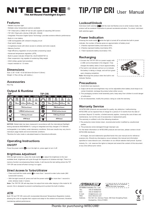
®The All-Round Flashlight ExpertUser ManualTIP/TIP CRIFeaturesMetallic keychain lightMultiple colour temperature options availableTIP: Fitted with a CREE XP-G2 S3 LED capable of outputting 360 lumens • TIP CRI: Fitted with a Nichia 219B LED, CRI≥90Integrated “Precision Digital Optics Technology” provides extreme reflector performance Built-in Li-ion batteryUSB rechargeable with onboard charging circuit Dual switch design4 brightness levels with direct access to ultralow and turbo outputs Memory functionHigh-efficiency regulation circuit provides unwavering output Advanced temperature regulation (ATR)Built-in power indicator (Patent No. ZL201220057767.4) Rear suspension ring capable of sustaining 30kg weight HAIII military grade hard-anodized Impact resistant to 1.5 metreDimensionsSize: 2.39” ×0.96” ×0.53”(60.8mm×24.5mm×13.8mm)Weight: 0.75oz (23.5g, with battery )AccessoriesKey ringOutput & RuntimeNOTICE: Stated data has been measured in accordance with the international flashlight testing standards ANSI/NEMA FL1 using an integrated and fully charged 3.7V 500mAh rechargeable Li-ion battery under laboratory conditions. End-user results may vary due to individual usage habits and environmental conditions.*Runtime for turbo mode is calculated based on theoretical arithmetic .Operating InstructionsON/OFFPress the power switch to turn the light on, press again to turn it off.Brightness AdjustmentWith the light turned on, press the mode switch to adjust the brightness to the next available level, brightness will cycle through the sequence of ultralow-mid-high. There is a memory function accompanying these modes, it will resume the last setting where the TIP /TIP CRI was turned off when turning it on again.Direct Access to Turbo/UltralowPress and hold the mode switch for more than 1 second to enter turbo mode (360 lumens/220 lumens).With the light turned off, press and hold the power switch for more than 1 second to enter ultralow mode (1 lumen).Note: The TIP/TIP CRI will step down its output from turbo after staying in this mode for 30 second, this is designed to prevent overheating and to protect the built-in battery.ATRBoth TIP and TIP CRI come with incorporated Advanced Temperature Regulation module, allowing the units to regulate their outputs and adapt to the ambient environment, therefore maintaining optimal performance.Lockout/UnlockHold down both switches until the main led flashes once to enter lockout mode, the product will be rendered inoperative to prevent accidental activation. To unlock, hold downboth switches again.Power IndicationPressing the mode switch while the light is turned off to activate the built-in power indicator, the number of flashes gives an approximation of battery level:1. 3 flashes represent battery level above 50%.2. 2 flashes represent battery level below 50%.3. 1 flash represents battery level below 10%.RechargingPrecautions1. Avoid direct eye exposure.2. Output will be dim and brightness may not be adjustable when battery level drops to to certain threshold, recharge the product when either occurs.3. This packaging contains small assembly parts, keep away from children to avoid danger of suffocation.4. Do not disassemble, modify this product, doing so voids the warranty.Warranty ServiceAll NITECORE products are warranted for quality. Any defective / malfunctioning NITECORE can be repaired free of charge for a period of 12 months from the date of purchase. Beyond 12 months, a limited warranty applies, covering the cost of labor and maintenance, but not the cost of accessories or replacement parts.The warranty is nullified in all of the following situations:1.The product(s) is/are broken down, reconstructed and/or modified by unauthorized parties.2. The product(s) is/are damaged through improper use.For the latest information on NITECORE products and services, please contact a local NITECORE distributor.※All images, text and statements specified herein this user manual are for reference purpose only. Should any discrepancy occurs between this manual and information specified on , information on our official website shall prevail. Sysmax Industry Co., Ltd. reserves the rights to interpret and amend the content of this document at any time without prior notice.Thanks for purchasing NITECORE!SYSMAX Industry Co., Ltd.TEL: +86-20-83862000 FAX: +86-20-83882723 E-mail: *****************Web: Address : Rm1401-03, Glorious Tower, 850 East Dongfeng Road,Guangzhou, China 510600Please find us on facebook: NITECORE Flashlights201608091.Connect the TIP/TIP CRI to a power supply with a USB cord as illustrated in the diagram. Fully charges the battery takes 2 hours approximately.2.The built-in red indicator will turn on to indicate the battery is taking a charge, and will turn green upon charging completion.Note: Recharge the product when the built-in red indicator flashes.150360351*30min 1h 30min 6h 30min 46h 74m (Beam Distance)1,400cd (Peak Beam Intensity)IP54 (Rated)1.5m (Impact Resistant)95240221*30min 1h 30min 6h 30min 46h56m (Beam Distance)810cd (Peak Beam Intensity) IP54 (Rated)1.5m (Impact Resistant)TIPTIP CRI。
pcm-d50英文说明书

For the customers in the USA and Canada
RECYCLING NICKEL METAL HYDRIDE BATTERIES Nickel Metal Hydride batteries are recyclable. You can help preserve our environment by returning your used rechargeable batteries to the collection and recycling location nearest you.
3-277-770-11(2)
Linear PCM Recorder
Operating Instructions
PCM-D50
© 2007 Sony Corporation
Owner’s Record
The model number is located at the rear and the serial number is located inside the battery compartment. Record the serial number in the space provided below. Refer to them whenever you call upon your Sony dealer regarding this product.
– Reorient or relocate the receiving antenna. – Increase the separation between the equipment and receiver. – Connect the equipment into an outlet on a circuit different from that to which the receiver is connected. – Consult the dealer or an experienced radio/TV technician for help. If you have any questions about this product, you may call: Sony Customer Information Services Center 1-800-2ation of Conformity Trade Name: SONY Model: PCM-D50 Responsible Party: Sony Electronics Inc. Address: 16530 Via Esprillo, San Diego, CA 92127 U.S.A. Telephone Number: 858-942-2230 This device complies with part 15 of the FCC Rules. Operation is subject to the following two conditions: (2) This device may not cause harmful interference, and (2) this device must accept any interference received, including interference that may cause undesired operation.
优麦CM828智能混音器说明书091028

A0906M-2.0Warning:Do not put the machine in rainy or damp placesin case of fire or electricity shock. Do not placecontainers with liquid on the machine.RoshINDEXI. Brief introduction of the product1. Brief introduction…………………………………………………………………2. Front panel…………………………………………………………………………3. Back panel…………………………………………………………………………1.Priority Set-up……………………………………………………………………2.Phantom Set-up …………………………………………………………………3. Low Cut Set-up…………………………………………………………………4. ID Set-up …………………………………………………………………………1.Microphone Input …………………………………………………………………2.Audio Output ………………………………………………………………………3.Earphone Monitor…………………………………………………………………4.Extension Connection ……………………………………………………………5.External Control …………………………………………………………………6.Power Supply Connection ………………………………………………………7. Volume Control …………………………………………………………………… 1.Audio Testing ……………………………………………………………………… …………………………………………………………. …………………………………………………….....1.Trouble Clearing ………………………………………………………………….2.Package List ……………………………………………………………………...II. Menu Set-up III. Connection IV. System TestingV.Technology Parameter VI. Application Reference VII. Appendix 121210119997-8665544432215.Reset (4)I. Brief IntroductionThe new smart digital auto mixer, monitored by high-speed DSP microproces-sor.It can be connected to low impedance microphone, neck microphone and wireless microphone or other line signals . digitally controlled, It has an oper-ating interface with a liquid screen. It is convenient to use with a simple and cl-ear menu.Adopting high-speed DSP digital control technology, it solves the probl-em of character skipping, it supports RS -232 External Control . At most16 extensions be used .Smart mixers for conferences, with its new functions and flexible application, will lead tr-aditional conferences, which were conducted in simulation mode, to a new smart age. Microphone, noise, and feedback are controlled by DSP micro processor, which improvesthe quality of sound. It is easy and convenient to operate , saving the trouble of connectingit to an external computer control interface.RS 232 external -controlled port to expand the mixer's application. Theclosing and opening of the noise gate can be controlled through anexternal control box, or it can be connected to a central control system.Each line is connected to phantom power supply, which can be selectedseparately, and it can be connected to all kinds of microphones conveniently.Each line is equipped with low-cut circuit , which can be selected separately,avoiding low-frequency noise.The channel gate can be opened automatically and quickly. The action levelcan be set up automatically.NOMA : It can adjust output level automatically , avoiding whistles by preve-nting the whole system from attenuating when using multi-extensions.2.Front panel1.Liquid Screen1.Function Set-up buttons3.Master Volume ( Tuning the master volume )4.Lock indicating light ( Indicating working mode )5.Volume POT for each line ( Tuning the volume of each line )6.Frequency General Output Level Indicating Line( Indicating the volume level of the general output )7.Channel indicating light ( appearing bright when it is on )8.Earphone monitor Volume POT ( Tuning the volume of earphone )9.Two channeled 6.3 earphone plug ( connected to the earphone )10.Power ( turning on/off the mixer )3.Back Panel1.Power Input ( Connected to external power supply AC 15V )2.RS 232 controlled Input Port ( connected to external control or central control )3.Extension Connecting Port ( Connected to it when more than one extensionis used.)4.Audio Signal General output Port ( connected to amplifiers. )5.Channel Input level switch ( Indicating microphone level when it ispopped, line level when it is pressed ).6.Channel gain Potentiometers - (adjust the input signal magnification is adj-usted clockwise to increase)7.Channel Input Port ( Connected to all kinds of microphones or other line levelfrequency signals. )1.PRI ORI TYPRIORITYPHANTOMLOW CUTID SETMENU123II. Menu Set-upSelect Priority in the menu, press the button “enter ” to enter the sub-menu, then press the D- pad to set up the required status. The black squares from left to right represent the status of 1-8 channels. Press the button “up ” to move the black square to “on ”, which means setting up “priority ”. Press the button “enter ” to confirm before exit.Function : It is set up as a channel for speech priority, which is only used by the host of a conference.Function :RESET2.PHAN TOM(It has the same setting- up procedures asthe one applied to “Priority “).When using a condenser microphone powered by phantom power , it is necessary to set up Phantom. Äll the required channels should beturned on. Turn off the phantom power by entering the the sub- menu when Phantom is not used.3.LOW CUT(It has the same setting- up procedures asthe one applied to “Priority “).Turn on the low-cut if hums occur when a microphone is used. Actuating circuit is ( 20 dB/oct, 130 Hz ) . It can eliminate low-frequency hums.4.ID SETPress the D-pad to set up .When more than one mixer extension is used, it is necessary to set up ID code for each . mixer. The ID address code is 1 when only one mixer is used.Note : The ID address code is in correspondence with the address of the camera and optical spot. For details, please refer to the extension conn-ection and the mapping table of ID address code.5.ResetAttention when using this function : Reset Function will return allFunction setup to Factory Reset.1.GND2.+3.-+-GNDIII. CONNECTION1.Microphone InputNote :Phantom Condenser microphone refer to ( II. 2 ). Turn on Phantompower. Input level selection button is popped out .Dynamic Microphone refer to ( II.2 ) , Turn off Phantom power. Input level selection button is popped out .Condenser microphone powered by battery refer to ( II. 2 ) . Turn off Phantom power. Input level selection button is popped out or pressed. Other line level audio equipment ( for example , when using a wireless microphone, connect the receiver's line output to the input port of the mixer first ) --- refer to ( II. 2 ) . Turn off phantom power. Input level se -lection button is popped out .Note : Phantom condenser microphone is recommended for best result . 2 . Audio OutputThe general audio collimated output Cannon can output level 16dBV at the maximum and impedance of 75 Ω. Use a balance line to con -nect it to the amplifier or the “Line” level input port of the mixer.Note : The line level signal of the general output port is above odBV.Do not connect the signal of the general output to the MIC input of the mixer's shunt . Or it will cause level mismatch , making a lot of noise. The accessory line is recommended or you can refer to the following circuit diagram.Connected to the generalIf the input signal is too small or too large, an appropriate adjustment can be caused by distortion "GAIN" potentiometer!3.Earphone MonitorConnect the earphone 6.35 to the front panel, monitor the earphonejack. Please tune the volume potentionmeter to the suitable positionaccording to actual need. The signal of the earphone is not controlledby the general volume potentionmeter. When tuning the volume ofthe earphone, do not tune the general volume potentionmeter.4.Extension ConnectionWhen using multiple mixers, use a “RJ-45 terminal sub line” to connect“LINK IN ” at the back panel of the mixer to “LINK OUT ” of anothermixer.connected to the 4th mixer LINK OUT ,3216.External ControlConnect the external control or central controlled equipment to the RS-232 port of the mixer. All the channels should be turned on or off.Mixer RS-232 protocolmunication protocol with central-controlled equipment : CentralControl machine is mainly used to give commands. ( Switch on /offthe microphone )munication method :The transmission speed is 9600bps, data mode is 1, 8, 1, 1, one startingbit, 8 data bits, one non-checking bit ( set as 1, non-defined ) , one stopbit. Effective commands are of 8 bits.Note :1.Attention should be paid to the transmitting time of the the checking bitand stop bit if it is transmitted under simulation RS -232 protocol.2.Attention should be paid to errors of the the transmitting speed, whichis better set between 9300bps to 9800bps.B.Arrange a fixed address code for the mixer after the extensionconnection is done. For details, please check ID Address CodeTable.Central control or external control should be connected tothe RS -232 port of the first mixer.C.Data TransmissionOA5H + XXH ( the address of the mixer ) + XXH ( the data of the microphone ) P.S : OA5 H is the checking code of the mixer. The addresses of the mixers ( 1-16 ) , which use ( OOH- OFH ) to indicate the data of the microphone,should be in correspondence with the following table. Data is transmitted according to actual demand.When switching on/off the microphone, the three data package aboveshould be transmitted in a row. No other data command is to be madein between .The reference table for the control bits of the microphone8 bits control data bit 7 …………………………………….Corresponding microphone MIC 8 ……………………………………1means turning on the microphone0means turning off the microphoneFor example : If you want to turn off the first microphone connected to the first mixer, OA 5 01 H OFEH should be transmitted And if you want to turn on the first microphone connected to the first mixer, OA 5 01 H OFEHshould be transmitted7.Power ConnectionThe mixer adopts AC-AC external power supply. It should be connected to commercial power AC 220 V, which will be transformed into two sets of AC 15 V power by using a step-down transformer. And it is connected to the input interface of the mixer's back panel.8.Volume TuningVolume Tuning Tune the volume potentionmeter in the corresponding channel of the front panel, “2 o' çlock ” is recommended for best result. IV. System Testing1.Audio TestingTest audio after all the equipment has been connected.1.Tune the volume control and master volume control of every channelof the mixer's front panel to “2 o' clock “.2.Turn on + 48 V phantom power if the microphones are powered byphantom power3.Set up Input level. The button should be popped out if a microphoneis used, and be pressed when inputting LINE level4.Turn on the power of the mixer. When a microphone is used, the levellight can be seen.5.Turn on the power of the amplifier, tune the volume to the suitableposition.6.Speak by using every microphone in order, and listen to the volumeof every microphone, make sure they are of the same volume.7.Tune the master volume to the suitable position. Make sure nowhistles occur when using the microphone.8.Hum can be eliminated by turning on Low Cut.V. Technology ParameterInput Impedance ……………………………..MIC 4.3 K LINE 28 KΩOutput Impedance…………………………….75ΩMaximum Input Level…………………………MIC- 24 dBV LINE 16 dBV Maximum Output Level………………………..+16 dBVStandard Input Level………………………….MIC-43 Dbv LINE 0 dBVFrequency Response…………………………..20Hz-20KHZTHD + N…………………………………….. 0.03%S/ N…………………………………………. 85 dBLOW CUT…………………………………..130Hz 18 dB octPower Supply………………………………AC 15 VConsumed Power……………………………25 WSize…………………………..434* 235 * 43 mmVI. Application ReferenceExternal ControlVII. Appendix1. Trouble ClearingProblems Cause Approaches ReferenceThe volume is difficult to control ; whistles happen often 1. Wrong connection2. Gain incoordinateshift the Input Interface III. 2Noise 1.Other interference2.Check the ground lines3.Check the microphone1. Eliminate interference2. Use one connection spot3. Change the microphoneLow- Frequency hums 1. The microphone hasno wind - resistant cotton2. Low Cut is not selected1. Use microphones thathave wind-resistant cotton2. Select Low CutII. 3The Output Level light is not bright Volume is not properlytunedTurn up the volume of themixerIII. 8No sound from the microphone 1. Phantom power is notturned on2. Wrong selection forInput Level3. The microphone is broken1. Turn on Phantom power2. Adjust Input Level3. change the microphoneII. 2III. 1RS -232 External Control doesn't work 1. Wrong connection2. Wrong selection for Baud rate3. Wrong Data1. Adjust connecting line2. Reset baud rate3. Check dataIII. 62.Package ListPower supply line -------------------- 1 Adaptor ---------------------------------1 RJ -45 External line ------------------1Audio output line ----------------------1Corner braces for fixing (2)Manual (1)Warranty Card ------------------------ 1 Certificate of Approval -------------- 1警告:请勿将本机置于雨水或潮湿的环境中, 以免发生火灾或触电.为防止水滴溅入, 请不要将盛有液体的容器放置在本机上.Rosh目录一、产品简介1.简介 ...........................................12.前面板 .........................................23.后面板 .. (2)二、功能设置1.话筒输入 .......................................53.低频哀减切设置 ................................. 42.幻像电源设置 ................................... 41.优先功能设置 ................................... 33.耳机监听 .......................................64.扩展连接 .......................................64.地址码设置 .....................................45.外部控制 .......................................7-86.电源连接 .......................................9四、系统调试1.音响调试 (9)2.音频输出 ....................................5三、安装连接7.音量旋钮调节 (9).10五、技术参数 ...............................11六、应用方案参考(图) .........................七、附录1.简单故障排除 ................................122.包装配件清单 .. (12)5.系统复位 (4)二、功能设置1.优先功能设置(PRI ORI TY )PRIORITY PHANTOM LOW CUT ID SETMENU(总菜单界面)在总菜单界面选择PRIORITY 按下中间确定按钮进入子菜单,进入优先功能设置子菜单后通过方向按钮设置所需的状态.黑色方格从左到右分别表示1-8通道状态,按"向上"方向键把黑色方格移到"ON "位置表示开启优先功能,设置完毕再按一下确认按钮退出.优先的作用:是指被设置为优先发言的通道,在任何情况下都可以发言,不受限制.一般优先发言的通道提供给会议主持人使用.123RESET2.幻像电源设置(PHANTOM)功能设置步骤与优先设置一样!在使用幻像电源供电的电容话筒时,需进行此功能设置,把所需的通道幻像电源开启.没有用到幻像电源时,进入此子菜单相应关闭幻像电源.3.低频哀减切设置(LOW CUT)功能设置步骤与优先设置一样!在话筒发言时出现不雅喷音时,开启低频哀减功能.电路动作为(20 dB/oct,130Hz)有效清除低频喷音的出现.对应通道可单独.4.地址码设置(ID SET)操作方向按钮进行设定.!在多台混音器扩展使用时,需要对各台机进行地址码设置.单机使用时地址码为1.注意,地址码的设置与摄像机的地址和视像点有对应的关系.详细见扩展连接和地址码对应表.5.系统复位(RESET)选用此功能时需注意:复位功能将把各项功能设置恢复到出厂设置.卡侬母头连接混音总输出 双声6.35插头连接到调音台LINE输入5.外部控制通过使用外部控制器或中控设备,连接到混音器 RS-232 端口.发送控制指令控制混音器各通道开启或关闭!混音器RS-232通讯协议:1.与中控机通讯协议.中控机主要用于下发控制指令(开关话筒)A.通讯方式:传输速率为9600bps,数据方式为: 1 , 8 , 1 , 1 , 一位起始 位,8位数据位,一位无校验位(设为1,未定义),一位停止位.有效控制 指令均为8位数据格式.注意:1.如果是模拟RS-232协议发送,需注意校验位和停止位的发送时间.2.注意速率的误差.最好在9300bps----9800bps之间.B.在扩展连接好后,给混音器编一个固定的地址码,具体查看地址码 设置表,中控或外部控制器连接到第一台混音器RS-232端口。
AIC1633ACN资料

AIC1633 2-Cell, 200mA, Step-Up DC/DC ConverterFEATURESHigh Efficiency Up To 87%.Adjustable Output Voltage with Two Resistors (AIC1633A)Power-Saving Shutdown Mode (7µA typical).Internal 0.8A Switch.120KHz Switching Rate.Adjustable Switch Current Limit.On-Chip Low Battery Detector.APPLICATIONSPocket Organizers.Electronic Dictionaries.Cameras.Pagers.Bar-Code Scanners.LCD Displays.Battery Backup Supplies.Portable Instruments. DESCRIPTIONT he AIC1633 is a high efficiency step up DC/DC converter. Only four external components are required to deliver a fixed voltage of 3V, 3.3V, or 5V. The output voltage can be externally set to an arbitrary value below breakdown voltage of the power switch for AIC1633A. Efficiency beyond 83% can be easily achieved at 70mA load with 2.2V to 3V input voltages.L ogic-controlled shutdown mode is provided for power saving. Switch current limit can be programmed with a resistor. The low battery detector can be configured as a linear regulator or a burst mode controller performing an extremely low supply current operation.120KHz switching rate reduces the inductor size.Inductors of 47µH to 150µH inductance are recommended for most applications.TYPICAL APPLICATION CIRCUITH igh-Efficiency Step-Up DC/DC ConverterAIC1633ABSOLUTE MAXIMUM RATINGSSupply Voltage .........................................................……………………....................... 7.0V Operating Temperature Range ...................................……….……................. -20°C ~ 80°C Storage Temperature Range .........................................……..………....... -65°C ~ 150°CTEST CIRCUITR efer to Typical Application Circuit. ELECTRICAL CHARACTERISTICS (V IN=3.0V, Ta=25°C, unless otherwise specified.)P ARAMETERT EST CONDITIONSM IN. T YP . M AX.U NITI nput Voltage1.8 7 VO utput VoltageI LOAD =70mAA IC1633A IC1633-3A IC1633-5 3.16 2.88 4.80 3.3 3 5 3.44 3.12 5.20VS witch off Current105 140 µAN o Load CurrentA IC1633/AIC1633-3 A IC1633-5 160 250µAS hutdown Mode Current7 15 µAS hutdown Recovery TimeV IN =2.5V, I LOAD =70mA 1.8 m SELECTRICAL CHARACTERISTICS (CONTINUED)P ARAMETERT EST CONDITIONSM IN.T YP .M AX.U NITEfficiencyI LOAD =70mAA IC1633/AIC1633-3A IC1633-58786%L ine RegulationI LOAD =40mAA IC1633, V IN =2.0~3.3VA IC1633-3, V IN =2.0~3.0VA IC1633-5, V IN =2.2~4.5V 0.6 0.60.5%V OUTL oad RegulationI LOAD =170mAA IC1633/AIC1633-3A IC1633-5 0.60.5%V OUTO scillator Frequency 90 120 150 K HzL BI Pin Trip Point1.17 1.22 1.27 VF B Threshold VoltageA IC1633A 0.598 0.617 0.636 VS W “ON Resistance” AIC1633/AIC1633-3 A IC1633-51.751.25ΩL BO “ON Resistance” V IN =2V 45 ΩS W Off Leakage 1 µAI nput Pin Bias Current 10 n A/Pin O utput Pin Leakage10 n A/PinTYPICAL PERFORMANCE CHARACTERISTICSSwitch Voltage vs CurrentI SW (A)V S W (V )0.511.522.500.511.522.53SW ON Resistance vs TemperatureTemperature (°C)102030405060708011.21.41.61.82S W R D S O N (Ω)TYPICAL PERFORMANCE CHARACTERISTICS (CONTINUED)No Load Supply Current vs Input Voltage140160180200220240260280V IN (V)I S (µA )No Load Supply Current vs TemperatureTemperature (°C)I S (µA)01020304050607080100140180220260300Shutdown Mode Supply Current vs Input Voltage11.522.533.544.5577.27.47.67.888.2V IN (V)I S (µA )Shutdown Mode Supply Current vs TemperatureTemperature (°C)02040608077.47.88.28.699.4V IN =3VI S (µA )Oscillator Frequency vs Input VoltageV IN (V)F r e q u e n c y (K H z )1 1.52 2.53 3.54 4.5560708090100110120130Oscillator Frequency vs TemperatureTemperature (°C)F r e q u e n c y(K H z )117118119120121122123TYPICAL PERFORMANCE CHARACTERISTICS (CONTINUED)Maximum Load Current vsR ILIM (K Ω)50100150200250300I L (m A )Maximum Load Current vs50R ILIM (K Ω)I L (m A )BLOCK DIAGRAMSGND SWLBOVINCGNDLBIVOUTAIC1633PIN DESCRIPTIONSA IC1633-30/ AIC1633-33 / AIC1633-50PIN 1: ILIM/SD- 1. Connected to VIN pin througha resistor to set the switchpeak current. It serves toprotect IC and inductor, aswell as to improve efficiencyand output ripples. However,the current limit resistor limitssupply capability of theAIC1633. (See typicalperformance characteristics).The ILIM/SD pin should beshorted to VIN pin if limitingon switch peak current is notintended.2. The AIC1633 goes inshutdown mode andconsumes less than 10µAwhen ILIM/SD pin is pulled toground.PIN 2: VIN-Input supply.PIN 3: SW-Drain of the power switch, to beconnected to inductor/ diode.PIN 4:SGND- Ground connected to source ofpower switch.PIN 5:CGND-Ground for control circuits of theIC. It should be separated fromSGND to avoid the interference.PIN 6:LBO-Open drain output of the batterylow detector, with 45Ω “ONresistance” at VIN =2V. It is pulledlow when the voltage on LBI pinis below 1.22V.PIN 7:LBI-The noninverting input of thebattery low detector, of which theinverting input is internallyconnects to 1.22V voltagereference.PIN 8:VOUT-The output voltage feedbacks tothe IC through this pin.A IC1633APIN 1:ILIM/SD-1. Connected to VIN pin througha resistor to set the switchpeak current. It serves toprotect IC and inductor, aswell as to improve efficiencyand output ripples. However,the current limit resistor limitssupply capability of theAIC1633A. (See typicalperformance characteristics).The ILIM/SD pin should beshorted to VIN pin if limitingon switch peak current is notintended.2. The AIC1633A goes inshutdown mode andconsumes less than 10µAwhen ILIM/SD pin is pulled toground.P IN 2:VIN- Input supply.P IN 3: SW-Drain of the power switch, to beconnected to inductor/ diode.P IN 4: GND- Ground.P IN 5:FB-Output voltage can either beinternally set to 5 volt bygrounding FB pin, or be externallyset to an arbitrary voltage byapplying to FB pin the dividervoltage of two divider resistors.V OUT voltage is given by thefollowing equation:10.617VR2R1OUT−=where R1 = Resistor connectedbetween FB pin and VOUT pin.R2 = Resistor connected betweenFB pin and ground.V OUT=Output voltage to be set.P IN 6:LBO-Open drain output of the batterylow detector, with 45Ω “ONresistance” at V IN=2V. It is pulledlow when the voltage on LBI pin isbelow 1.22V.A IC1633A (continued) P IN 7:LBI-The non-inverting input of thebattery low detector, of which the inverting input is internally connects to 1.22V voltage reference.P IN 8:VOUT-The output voltage feedbacks tothe IC through this pin. If output voltage was externally set, the VOUT pin can be tied to any low impedance node with voltage between the external power switch threshold and 7VAPPLICATION EXAMPLESLoad Current (mA)E f f i c i e n c y (%)F ig. 13V Output Step-Up ConverterLoad Current (mA)65707580859095E f f i c i e n c y (%)F ig. 2 5V Output Step-Up ConverterAPPLICATION EXAMPLES (CONTINUED)606570758085Load Current (mA)E f f i c i e n c y (%)S tart-Up V IN Voltage = 1.4VF ig. 3 1-Cell Input 3V Output Step-Up ConverterLoad Current (mA)7075808590E f f i c i e n c y (%)F ig. 4 4-Cell Input Step-Up/ Step-Down Converter7580859095100Load Current (mA)E f f i c i e n c y (%)F ig. 5 3-Cell Input 3V Output Step-Down ConverterAPPLICATION EXAMPLES (CONTINUED)F20406080Load Current (mA)E f f i c i e n c y (%)F ig. 6 Boost-Driven 5V Output Step-Down ConverterFig.7 Adjustable Output Voltage Step-Up ConverterPHYSICAL DIMENSION8 LEAD PLASTIC SO (unit: mm)SYMBOLMIN MAX A 1.35 1.75A10.100.25B 0.330.51C 0.190.25D 4.80 5.00E3.804.00e 1.27(TYP)H 5.80 6.20L0.401.278 LEAD PLASTIC DIP (unit: mm)SYMBOL MIN MAX A10.381—A2 2.92 4.96b 0.350.56C0.200.36D 9.0110.16E7.628.26E1 6.097.12e 2.54 (TYP)eB —10.92L2.923.81。
SWITCHING MODE POWER SUPPLY USER MANUAL

SWITCHING MODE POWER SUPPLYUSER MANUALKeep this manual in a safe place for quick reference at all times.This manual contains important safety and operation instructions for correct use of the power supply. Read through the manual and pay special attention to the markings and labels of this unit and equipmentto be connected.Pay special attention to these two types of notices used in this manualWARNING :Failure to observe this warning may cause injury to persons and damage to power supplyor connected equipment.CAUTION :Failure to observe this warning may result in damage to equipmentand Improper functioning of the power supply.WARNING :1.Do not use this power supply near water.2.Do not operate or touch this power supply with wet hands.3.Do not open the casing of the power supply when it is connected to ac mains.4.Refer all servicing to qualified service personnel only.5.Before replacing the AC fuse at AC socket , find out and clear up the cause first.6.Replace the AC fuse with the same type and rating as the original fuse.7.The max. output voltage of Model 72-8340 is 60VDC, avoid touch ing the metal contact part of theoutput terminals.CAUTION :e a grounded 3 pin AC source .2.This unit is for indoor use only .3.Do not operate or place this unit in a humid, dusty, in direct sunlight location or near any heat source.4.Before plugging into local AC mains, check with the rating label at the back of the unit.5.Do not block any ventilation openings of the unit.6.This unit must be used within the specified rating, regular excessive continuous loading may causedamage to the power supply.7.The gauge size of input power cable must be at least 0.75mm2 and the total length of power cable mustnot exceed 3m.OPERATION ENVIRONMENTAL CONDITION•10-80% R.H.•Maximum relative humidity 80% for temperature up to 31°C decreasing linearly to 50% relative humidity at 40°C.•Altitude up to 2000m•Installation category : CAT 2•Pollution degree: 2•Mains supply voltage fluctuation up to ±10% of the normal voltageINTRODUCTIONSThis series of 100W Switching Mode Power Supplies with Current Limiting Control, is designed with the objectives of high accuracy, compactness and easy portability. Rotary encoder are used for voltage and current control. 4 digit display LCD of voltage and current for high precision.CONTROLS AND INDICATORSc Power Switch :Turns the power supply on–off, when it is on the front display lights up.d AC Input Socket with Fusee Concealed Fuse box ( ply open the cover to get to the fuse)f Output Voltage Tuning knobg Output Current Tuning knob.h Output On/Off push buttoni Output Terminal Positive (+) Red color.j GND Terminal ( ) Green colorChassis ground terminal, normally this is to be short to (+) or (-) as required by user.k Output Terminal Negative (-) Black color.l LCD Display panel showing :4 digit voltage, current meter, (CV) constant voltage mode, (CC) constant current mode,Output Terminal on/off stateOPERATIONSGround ConnectionDepending on the application, the power supply output terminals can be grounded in any one of the following grounding conditions :Negative ground – black (-) negative terminal is shorted with green GND terminal.Positive ground – red (+) positive terminal is shorted with green GND terminal.Floating ground – green terminal is not shorted with any of the output terminals.Remarks :When operating this power supply as a floating ground, high impedance leakage can exist between the power supply circuitry and the chassis ground.Basic Mode of OperationThis power supply is designed to operate as a constant voltage source or as a constant current source. Automatic crossover to either mode of operation occurs when the load condition changes as following :Constant Voltage (CV), Automatic crossover & Constant Current (CC)The power supply functions as a constant voltage source (CV) as long as the load current is less than the preset current limiting value. When the load current is equal to or greater than the preset current limiting value, the power supply will automatically cross over to the constant current mode, voltage will drop, (CC) will show on the LCD display panel and it will operate as a constant current source.When the load current drops below the preset current limiting value, the supply returns to constant voltage (CV) mode.Presetting Current Limiting Value (CC)Switch on the power supply, adjust the output voltage to about 3V, turn off the output terminal with push button h, icon becomes .Short the black and red output terminals and turn on the output terminal by h, icon becomes , adjust the current limiting value to your desired value say x Amp by tuning knob g. Turn off the output terminal and take out the shorting connection.The current limiting of power supply has been preset to x Amp for the whole range of output voltage.Connection and Operation Procedure1.After checking with the rating label plug in to AC mains .2.Switch on the power supply and the LCD display should be on at the same time.3.The (CV) icon should be shown on the display.4.Turn to current volume knob g to maximum clockwise if you do not require lower Current limiting value, otherwise do thepreset the (CC) limiting procedure.5.Set your desired output voltage and then turn off the output terminal by push button h.6.Connect to your load positive to positive and negative to negative.7.Turn on the output terminal again and check if display shows (CV).8.If display shows (CC), either your preset current limiting value is too low or your load requires more voltage and current .You need to re-access the voltage and current requirement of your load and increase the voltage or current accordingly until (CV) appears.Tracking Output Over Voltage Protection ( OVP )This is to protect the connected load in the event that the output voltage control circuit mal-functions, the maximum output voltage will not exceed 30% of the adjusted voltage value at the time of the operation.Over Temperature ProtectionWhen the temperature inside the power supply becomes higher than a pre-determined value, the output voltage and current of the power supply will automatically decrease to zero to prevent damage to power supply. When the temperature inside the power supply returns to about 65°C then the power supply will automatically return to operation again. SPECIFICATIONS72-8350 72-8345 72-8340Input Voltage (Jumper Selection)90 - 130 / 180 - 240Vac , 50 / 60Hz~Full Load Input Current at 230Vac0.83AOutput Voltage Adjustable Range 1.0 - 20Vdc 1.0 – 36Vdc 1.0 - 60VdcOutput Current Adjustable Range0 - 5A0 - 3A0 - 1.6AVoltage RegulationLoad from 10% to 100% Variation70mV50mV50mVLine from 180 to 264Vac Variation20mVRipple & Noise in r.m.s.5mVRipple & Noise (peak to peak)30mV30mV50mVCurrent RegulationLoad from 10% to 100% Variation20mALine from 180 to 264Vac Variation20mARipple & Noise (peak to peak)20mASwitching Operation Frequency80KHz to 120KHzPower Factor0.68Efficiency at Maximum Power84%85%85%Volt and Amp Control Type Rotary EncoderVoltmeter and Ammeter Display 4 DigitVoltmeter Accuracy±1% +5counts for range V≤5V±1% +5counts for range V≤10V±1% +5counts for range V≤20V±1% +3counts for range V>5V±1% +3counts for range V>10V±1% +3counts for range V>20V Ammeter Accuracy±1% +5counts for range I≤2A±1% +5counts for range I≤1A±1% +5counts for range I≤0.5A±1% +3counts for range I>2A±1% +3counts for range I>1A±1% +3counts for range I>0.5A LCD Indication CC, CV, Amp, Volt, Output ON-OFFProtection Short Circuit, Overload, Over Temperature, Tracking OVPCE Approvals LVD : EN 61010 , EMC : EN 55011Cooling System Natural ConvectionDimensions in mm (WxHxD)70 x 150 x 250mm / 2.8 x 6.0 x 9.8in.Weight in Kg2Kgs / 4.4LbsRemarks All the data are based on 230V 50Hz~Rev.2 05/2011 7673-3630-0001。
Pow-R-Command数字开关说明说明书

Pow-R-Command Digital SwitchEach PRC Digital Switch is completely customizable and can beprogrammed to precisely meet the needs of the customer’s lighting control strategy. This program is stored directly in the switch’s integrated memory, which adds to the robustness of the Digital Switch Network (DSN). In addition to its network communication capabilities, the Pow-R-Command Digital Switch has built-in inputs and outputs that allow the connection of photo sensors, occupancy sensors and dimmable LED drivers and fluorescent ballastsequipped with integral 0–10 Vdc dimming circuitry to achieve fully integrated zone lighting control from one device.Highlights•Network capability with existing Pow-R-Command 1000(E), 1500(E) and 2000(E) controllers • Up to 99 switches per single network•Onboard rotary switches for ease of addressing • Soft-touch 2-, 4- and 6-pushbutton options available • LED backlit buttons provide system status •Digital inputs for connecting low voltage switch or occupancy sensor• Analog input for connecting light level sensor • Analog output for dimming/daylight harvesting control • Standard single-gang box mounting • Standard Decora ® style wallplate•Black, white, almond and ivory colors availableFeatures•Digital Switch Network communication to compatible Pow-R-Command intelligent panelboards. Completely integrates into the facility’s Pow-R-Command automated lighting and load control system•Industry-leading customization where each switch pushbutton can control any Smart Breaker™ and/or group in the facility •Distributed intelligence achieved through integrated memory storage on each device• Onboard rotary switches for ease of device addressing •Digital Switch Network automatic discovery, eliminating initial software configuration steps•Multiple soft-touch pushbutton configurations allow for easy customization of the system. Momentary, gold-plated contacts for each pushbutton•LED backlit pushbuttons allow quick display of the current system’s status•Onboard digital and analog input/output allow connection of photo sensors, occupancy sensors and dimmable fluorescent ballasts and LED drivers equipped with 0–10 Vdc dimming circuitry •Standard single-gang switch wall box mounting. No special hardware is required. Fits standard Decora-type wall plateIntelligent Digital Switches for localoverride switching and dimming controlThe Pow-R-Command ™ Digital Switch is a state-of-the-art microprocessor-based low voltage device. Each switch has the ability to communicate directly to Pow-R-Command controllers through a dedicated Digital Switch Network. Each Pow-R-Command controller can have up to 99 PRC Digital Switchesconnected to the system. This gives distributed control throughout the entire facility at a muchlower cost of installation.Eaton is a registered trademark.All other trademarks are property of their respective owners.Eaton1000 Eaton Boulevard Cleveland, OH 44122United States © 2016 EatonAll Rights Reserved Printed in USAPublication No. PA01412012E / Z17493February 2016Physical•Mounts in standard single-gang box spacing •Device colors:• Black • White • Almond •Ivory•Custom labeling availableDevice I/O•Voltage output of 12 Vdc at 20 mA to power auxiliary devices such as a photo sensor or occupancy sensor •Analog input for a photo sensor or occupancy sensor •Digital input for occupancy sensors, 2- and 4-button only •Analog output: maximum of 10 mA current sinking for fluorescent ballasts and LED drivers equipped with 0–10 Vdc dimming circuitryElectrical•24 V/100 mA AC power is provided to each switchthrough the CAT -6 #23 AWG network cableOperating environment•Designed for indoor environment•Operating temperature: –10 ºC to 40 ºC (14 ºF to 104 ºF)•Relative humidity: 10% to 90% noncondensing •Atmosphere: non-explosive and non-corrosive•Vibration: stationaryapplication—NEMA ® Level ACertifications•FCC and UL ® approvedConfiguration input/outputDigital Switch Network (DSN)Digital Switch featuresHow to orderProduct line (3 digits)PRC = Pow-R-CommandLearn more at/lightingcontrol or email us at *************************otee:N For PRCE Digital Switch drawing references, visit /lightingcontrol .Follow us on social media to get the latest product and support information.。
- 1、下载文档前请自行甄别文档内容的完整性,平台不提供额外的编辑、内容补充、找答案等附加服务。
- 2、"仅部分预览"的文档,不可在线预览部分如存在完整性等问题,可反馈申请退款(可完整预览的文档不适用该条件!)。
- 3、如文档侵犯您的权益,请联系客服反馈,我们会尽快为您处理(人工客服工作时间:9:00-18:30)。
A Digitally Controlled Switch Mode PowerSupply Based on Matrix ConverterSomnida Ratanapanachote,Han Ju Cha,and Prasad N.Enjeti,Fellow,IEEEAbstract—High power telecommunication power supply systems consist of a three-phase switch mode rectifier followed by a dc/dc converter to supply loads at48V dc.These rectifiers draw sig-nificant harmonic currents from the utility,resulting in poor input power factor with high total harmonic distortion(THD).In this paper,a digitally controlled three-phase switch mode power supply based on a matrix converter is proposed for telecommunication ap-plications.In the proposed approach,the matrix converter directly converts the low frequency(50/60Hz,three-phase)input to a high frequency(10/20kHz,one-phase)ac output without a dc-link.The output of the matrix converter is then processed via a high fre-quency isolation transformer to produce48V dc.Digital con-trol of the system ensures that the output voltage is regulated and the input currents are of high quality under varying load condi-tions.Due to the absence of dc-link electrolytic capacitors,power density of the proposed rectifier is expected to be higher.Anal-ysis,design example and experimental results are presented from a three-phase208-V,1.5-kW laboratory prototype converter. Index Terms—Three-phase switch mode rectifier,total harmonic distortion(THD).I.I NTRODUCTIONM ODERN telecommunication power systems require several rectifiers in parallel to obtain higher current dc output at48V dc[1]–[4].Commercially available telecom-rectifiers[1]employ ac to dc conversion stage with a boost converter,followed by a high frequency dc/dc converter to produce48V dc(see Fig.1).This type of rectifier draws significantfifth and seventh harmonic currents resulting in near40%total harmonic distortion(THD).In addition,the rectifier dc-link capacitor stage is bulky,contributes to weight and volume.Furthermore,the presence of multiple power conversion stages contributes to lower efficiency.In response to these concerns,this paper proposes a digitally controlled switch mode power supply based on a matrix con-verter for telecommunication applications(Fig.2).Matrix con-verter topology employs six bidirectional switches to convert lower frequency(50/60Hz)three-phase input directly to a high frequency(10/20kHz)one-phase output.The output is then processed via an isolation transformer and rectified to48VManuscript received April28,2004;revised June29,2005.Recommended by Associate Editor J.R.Rodriguez.S.Ratanapanachote is with the Department of Electrical Engi-neering,Mahidol University,Nakhon Pathom73170,Thailand(e-mail: egsrt@mahidol.ac.th).H.J.Cha is with the Department of Electrical Engineering,Chungnam Na-tional University,Daejeon305-764,Korea(e-mail:hjcha@cnu.ac.kr).P.N.Enjeti is with the Department of Electrical Engineering,Texas A&M University,College Station,TX77843USA(e-mail:enjeti@). Digital Object Identifier10.1109/TPEL.2005.861197dc.Digital control of the matrix converter stage ensures that the output voltage is regulated against load changes as well as input supply variations while maintaining sinusoidal input cur-rent shape at near unity power factor.Advantages of the proposed topology are:•no dc-link capacitor required;•capable of operation over a wide input voltage range;•low total harmonic distortion(THD)in line current;•proper switching modulation results in smaller inputfilter;•unity input power factor over a wide load range;•higher efficiency with increased power density;•digital control facilitates external communication;enable parallel operation of several stages and implementation of complex closed loop control functions.The paper present a detailed analysis of the modulation scheme,discusses a design example and experimental results on a three-phase208-V,1.5-kW laboratory prototype converter.II.P ROPOSED S WITCH M ODE P OWER S UPPLYThe proposed digitally controlled switch mode power supply based on matrix converter is shown in Fig.2.Matrix converter topology employs six bidirectional switches to convert lower frequency(50/60Hz)three-phase input directly to a high fre-quency(10/20kHz)one-phase output.The output is then pro-cessed via an isolation transformer and rectified to48V dc. Digital control of the matrix converter stage ensures that the output voltage is regulated against load changes as well as input supply variations.Matrix converter is a direct ac/ac converter and operates without a dc-link[5].It has the advantage of bidirectional powerflow,controllable input power factor,high reliability, and compact design.High operating frequency of the system allows the size and weight of the transformer to be reduced. In this paper,space vector modulation technique applied to a matrix converter is employed.For hardware implementation,a three-phase to three-phase matrix converter module based on 1200-V IGBT introduced by EUPEC[6]is used.III.M ATRIX C ONVERTER PWM M ODULATIONIn the proposed topology a three-phase to one-phase ma-trix converter(Fig.3)employing twelve IGBT switches is employed.The PWM modulation is divided to two modes,rectifier mode and inverter mode,respectively.Fig.4illustrates the modula-tion modes of matrix converter as traditional ac/dc/ac conver-sion system.Due to the absence ofdc-link,is presented as afictitious dc voltage for analysis purposes.0885-8993/$20.00©2006IEEEFig.1.Conventional telecommunication switch mode power supply[1].Fig.2.Proposed digitally controlled switch mode power supply based on matrixconverter.Fig.3.Figure of three-phase to one-phase matrixconverter.Fig.4.Illustration of matrix converter operation.The operation of the matrix converter can be expressed math-ematically in a matrix formation.The fictitious dcvoltage,,is derived from the recti fier mode ofoperation(1)whereis recti fier mode transfer functionand is the input voltage vector.Matrix converter outputvoltage,,is derivedfrom the inverter mode of operationas(2)where is the inverter mode transfer function.The line cur-rent can be expressed in terms of recti fier and inverter mode transfer functionsas(3)The three-phase input voltagevectoris givenby(4)where is amplitude of input voltageand is input angularfrequency.A.Rectifier Mode of OperationAs detailed in the earlier section,matrix converter analysis is simpli fied by separating the recti fier and inverter mode of op-erations.The objective of the recti fier mode of operation is toFig.5.Recti fier space vector hexagon.create a fictitious dcvoltage from input voltage and to main-tain unity input power factor.Recti fier space vector hexagon is shown in Fig.5.The switching vectors in the hexagon in Fig.5are indicated by the switches from recti fier part in Fig.4.The placement ofspace vector referencevector,,within one sector is de fined by adjacent the switchingvectors,and .Theangle is angle of space vector reference vector.The duty cycles of the active switching vectors are calculated with recti fier mode mod-ulationindex,(5)(6)(7)Recti fier modematrix,,can be set up from switching func-tions S1to S6established by space vector method.Number of elementsin depends on the number of inputphases(8)(9)(10)(11)It can be statedthatand are the same functionas with phase shifting of23and23,respectively.From (1)and (4),the fictitious dcvoltage1.5(12)B.Inverter Mode of OperationThe objective of this mode of operation is to generate a high frequency single phase output voltage.The operating frequency in this mode is the same as desired output frequency.From the recti fier mode,fictitious dcvoltage,,is found.It is used as the input of single phase inverter part in Fig.2.Due to only one phase for the matrix converter output,the inverter modematrix,,has singleelement(13)(14)The switchingfunction,,can be generated as shown in Fig.6.The controlsignal,,is varied to obtain desiredma-Fig.6.Inverter mode switching function.trix converter output voltage.The switching function can be ex-pressedas(15)(16)From (2)and (12)andlet be inverter mode modulationindex(17)C.Proposed PWM Switching ModulationFrom (1)and (2),it can be shown that matrix converter output can be foundfrom(18)Equation (18),the transferfunction,,is representing the matrix converter switching function.Thus,switching function of matrix converter switches can be realized as follows.From (8)–(11),(13),and (14)wehave(19)(20)Block diagram of the proposed matrix converter modulation is shown in Fig.7.Each switch can be implemented with the logic gates as shown in Fig.8.Fig.7.Block diagram of the proposed matrix convertermodulation.Fig.8.Matrix converter switch gating signals generating through logic gates.IV .A NALYSIS OF THE P ROPOSED P OWER C ONVERSION S TAGE A.Voltage AnalysisIn the proposed topology,input source voltage is converted to high frequency voltage through operation of three-phase to one-phase matrix converter.From (1)and (2),the matrix converter output voltage is givenby(21)From (4),(8),and (13)wehave(22)where(23)(24)(25)Then(26)Equation (26)shows no dc component in the matrix converter output voltage.The high frequency ac output voltage is con-nected to isolation transformer stage.In order to generate 48V dc,the high frequency transformer performs step-down operation with suitable turnratio,.Theselected depends on value of input voltage and range of ma-trix converter modulation index and is detailed in the design ex-ample section.B.Line Current and Harmonics AnalysisIn this section the input line current is analyzed.Equation (3)shows the inputcurrent as a functionof and the recti fier/in-verter mode transfer functions.Now assuming the output cur-rent to besinusoidal(27)where is amplitude of output currentand is output angular frequency.The input current can be expressedas(28)From (28),linecurrentcan be expressedas(29)Substitute(14)and(24)–(29)yields(30)where is the input frequency in rad/s(2,60Hz)and is the output frequency in rad/s(2,10kHz).Substitutingand in(30),it is clear that the inputcurrent does not have any low frequency harmonic componentsand is of high quality.The high frequency componentsin areto befiltered by the input putfilter stage of the converter.V.D ESIGN E XAMPLEIn this section,a design example is presented for the fol-lowing input/output specifications.To facilitate calculation in per-unit,the following base quan-tities are defined1.5kW48V31.25A1.536Input linevoltage 4.33per unit.The matrix converter outputcurrent is givenby(31)where is the transformer turn ratio.Select4,0.25per unit.Neglecting losses,the utility line current can be expressedas(32)And the inputcurrent0.133per-unit.A.Input Filter DesignHigh frequency current components in the input current ofmatrix converter can befiltered viaafilter.The value offilter capacitor is selected by the following equation[7]:(33)where is the powerrating,is the peak of input voltage,and is angular inputfrequency.Fig.9.High frequency output voltage V of the matrixconverter.Fig.10.Output dc voltage(48V).Fig.11.Input line to neutral input voltageV and input current I.Fig.12.THD percentage at different loads.Fig.13.Proposed matrix converterprototype.Fig.14.Input voltage V ,matrix converter output voltage V ,and transformer secondary voltage V .(1:V [250V/div],2:V [500V/div],3:V [100V/div]).The value of filter inductor is chosenby(34)where is the cut-off frequency and is chosen to be lower than the switching frequency (10kHz).With the parameter values given in this design example,and cut-off frequency is chosen to be 1.7kHz:filtercapacitance60F;filterinductor150H.VI.S IMULATION R ESULTSIn this section,simulation results of the proposed approachare discussed.Fig.9shows the high frequency output voltage of the matrix converter.Fig.10shows the 48-V dc output voltage.Fig.11illustrates the performance of the proposed converter from utility perspective.It is clear for these results that input current is of high quality and is in phase with the input line to neutral voltage.Fig.12shows the variation of input current THD as a function ofload.Fig.15.Transformer primary V and secondary voltages V.(1:V[250V/div],3:V [50V/div]).Fig.16.Output dc voltage V and load current I .(3:V [50V/div],4:I[10A/div]).Fig.17.Input line to neutral voltageV and the input line current I at 1.5kW of output power.(2:I [5A/div],4:V [125V/div]).TABLE ID ESIGN S PECIFICATIONS OF THE P ROPOSED APPROACHVII.E XPERIMENTAL R ESULTSA laboratory prototype of the proposed digitally controlled switch mode power supply was constructed to meet the spec-i fications detailed in Section V .A commercially available ma-trix converter module:FM35R12KE3from EUPEC [6]was em-ployed.A digital signal processor (TMS320LF2407)was used for generating PWM gating signals and performing closed loop functions.Fig.13shows the prototype matrix converter unit.The unit is connected to bridge recti fier,which consists of four fast-recovery diodes (60EPU02),and an output filter to produce power supply voltage of 48V dc.Fig.14shows the inputvoltage,matrix converter output voltage (highfrequency)(connected to the transformer primary winding)and the transformer secondaryvoltage .Fig.15shows the transformer primary and secondary voltages with expanded time scale.Fig.16shows the output dc voltage (48V)and the load current.Fig.17shows the line to neutralvoltageand the linecurrent at 1.5-kW output power.It is clear that the input current is of high quality and unity power factor (see Table I)[8],[9].VIII.C ONCLUSIONIn this paper,a digitally controlled switch mode power supply based on matrix converter for telecommunication applications has been shown.The proposed space vector PWM method has been shown to yield high quality input current for varying load conditions.Experimental results on a 1.5-kW prototype have demonstrated the feasibility of a direct ac to ac matrix converter in telecommunication power supplies.R EFERENCES[1]Tyco Electronics,“Galaxy Switchingmode Recti fier 595Series,”Tech.Rep.,Feb.2003.[2] A.I.Pressman,Switching Power Supply Design .New York:McGraw-Hill,1997.[3]R.Redl and A.S.Kislovski,“Telecom power supplies and powerquality,”Proc.INTELEC ’95,pp.13–21,Nov.1995.[4]P.Enjeti and S.Kim,“A new dc-side active filter for inverter powersupplies compensates for unbalanced and nonlinear load,”in Proc.IEEE IAS Annu.Meeting ,Sep.28–Oct.41991,pp.1023–1031.[5]M.Venturini,“A new sine wave in,sine wave out,conversion tech-nique eliminates reactive element,”in Proc.POWERCON 7,1980,pp.E3-1–E3-15.[6]M.Hornkamp,M.Loddenk ötter,M.M ünzer,O.Simon,and M.Bruck-mann,“EconoMAC the first all-in-one IGBT module for matrix con-verters,”in Proc.EUPEC ,2005,[Online]Available:.[7] C.L.Neft and C.D.Schauder,“Theory and design of 30-hp matrixconverter,”IEEE Trans.Ind.Appl.,vol.28,no.3,pp.546–551,May/Jun.1992.[8]M.Kang,P.N.Enjeti,and I.J.Pitel,“Analysis and design of electronictransformers for electric power distribution system,”IEEE Trans.Power Electron.,vol.14,no.6,pp.1133–1141,Nov.1999.[9]H.Cha and P.N.Enjeti,“A three-phase AC/AC high-frequency linkmatrix converter for VSCF applications,”in Proc.PESC ’03,vol.4,Jun.2003,pp.1971–1976.Somnida Ratanapanachote received the B.Eng.degree from Mahidol University,Nakhon Pathom,Thailand,in 1995,and the M.Eng.and Ph.D.degrees from Texas A&M University,College Station,in 1998and 2004,respectively,all in electrical engineering.In 1995,she received a full scholarship from the Thai government and joined the Department of Electrical Engineering,Mahidol University.In 2004,she became a Lecturer at Mahidol University.Her research interests include ac/ac power converter,switch mode power supply,power quality,and power electronicapplications.Han Ju Cha received the B.S.degree in electrical engineering from Seoul National University,Seoul,Korea,in 1988,the M.S.degree from Pohang Insti-tute of Science and Technology,Pohang,Korea,in 1990,and the Ph.D.degree from Texas A&M Uni-versity,College Station in 2004,all in electrical en-gineering.From 1990to 2001,he was with LG Industrial Systems,Anyang,Korea,where he was engaged in the development of power electronics and adjustable speed drives.In 2005,he joined the Department ofElecrical Engineering,Chungnam National University,Daejeon,Korea.His research interests are high power converter,ac/dc,dc/ac and ac/ac converter topologies,power quality and utility interface issues for distributed energy systems,and advanced converters for informationdisplay.Prasad N.Enjeti (M ’85–SM ’88–F ’00)received the B.E.degree from Osmania University,Hyderabad,India,in 1980,the M.Tech degree from the Indian Institute of Technology,Kanpur,in 1982,and the Ph.D.degree from Concordia University,Montreal,QC,Canada,in 1988,all in electrical engineering.In 1988,he joined,as an Assistant Professor,the Department of Electrical Engineering Department,Texas A&M University,College Station.In 1994,he was promoted to Associate Professor and in 1998he became a Full Professor.He holds four U.S.patents and has licensed two new technologies to the industry so far.He is the lead developer of the Power Electronics/Power Quality and Fuel Cell Power Conditioning Laboratories,Texas A&M University and is actively involved in many projects with industries while engaged in teaching,research and consulting in the area of power electronics,motor drives,power quality,and clean power utility interface issues.His primary research interests are advance converters for power supplies and motor drives;power quality issues and active power filter development;converters for fuel cells,microturbine,wind energy systems,power electronic hardware for flywheel,ultracapacitor type energy storage/discharge devices for ride-through and utility interface issues.Dr.Enjeti received the IEEE-IAS Second and Third Best Paper Award in 1993,1998,1999,2001,and 1996,respectively;the Second Best IEEE-IA T RANSACTIONS paper published in mid-year 1994to mid-year 1995,the IEEE-IAS Magazine Prize Article Award in 1996,the Class of 2001Texas A&M University Faculty Fellow Award for demonstrated achievement of excellence in research,scholarship and leadership in the field,and he directed a team of students to design and build a low cost fuel cell inverter for residential applications,which won the 2001future energy challenge award,grand prize,from the Department of Energy (DOE).He is a Registered Professional Engineer in the state of Texas.。