SZ60B6中文资料
70个论坛大全

1.bd贴吧:全球最大的中文社区,这个热门程度不需要质疑。
地址:/2.2.新浪论坛:新浪是中国四大综合门户网站之首,它的人气众所周知。
新浪博客里面有众多的名人博客,新浪论坛同样人气值很高。
地址:/3.3.搜狐社区:与新浪差不多,四大门户网站之一。
地址:/4.4.天涯社区:许多爆炸性新闻的源头。
没有一个中文社区能够像天涯一样聚集到这么多高水平的写手。
如果你很能写,很会炒帖子,那么天涯无疑是最好的选择。
/5.5.腾讯QQ论坛:QQ的用户有多少?从这里就可以想象QQ论坛的热度。
/6.前五名以后的就直接贴出来了:6.TOM论坛:/7.7.猫扑:/8.8.网易论坛:/9.9.中华网论坛:/10.10. 上海热线论坛:/11.11. 西陆论坛:/12.12. 新华网论坛:/13.13. CCTV论坛:/forum/index.shtml14.14. 21CN社区:/15.15. 强国论坛:/16.16. 铁血论坛:/17.17. 华声在线:/index.asp18.18. CSDN技术社区:/19.19. 博客论坛:/20.20. 凯迪社区:/newbbs/index.asp21.21. 西祠胡同:/main.asp22. BT之家论坛:/23.23. 淘宝网论坛:/24.24. 粉丝网论坛:/25.25. 贪婪大陆:/26.26. 中国站长论坛:/27.27.动网先锋论坛:/28.28.焦点房产论坛:/community/29.29.Chinaren校园论坛:/30.30.我爱打折网:/31.31.影视帝国论坛:/32.32.榕树下社区/33.33.索爱手机论坛/34.34.263海云天/35.35.17173网游社区/36.36.泡泡俱乐部/default.htm37.37.水木清华BBS /guest-frames.html38.38.ABBS建筑论坛/39.39.凤凰网论坛/40.40.千龙社区/41.41.浩方社区/42.42.SoGua娱乐论坛/43.43.中国学生社区/44.瑞丽论坛/45.45.东方社区/46.46.深圳之窗社区/47.47.ENET论坛/48.48.爱词霸社区/49.49.金融界股票论坛/50.50.北大BBS /51.51.青青岛社区/52.52.泡泡堂社区/53.53.商都论坛/bbs/index.asp54.54.考研论坛/55.55.杭州网论坛-19楼/56.56.TOMPDA /57.57.沪江英语论坛/58.58.赢政天下论坛/59.59.联众游戏讨论区/60.60.红豆社区/61.61.天空游戏社区/index.php62.62.交大饮水思源BBS /63.63.倚天硬件/64.64.纵横财经/65.爱毒霸社区/66.木蚂蚁社区/67.喜满你论坛/68.网大论坛/69.四川天府论坛/70.中文之家论坛/71.1984影视。
SZ5056中文资料

Page 1 of 2
Rev. 03 : March 25, 2005
元器件交易网
ELECTRICAL CHARACTERISTICS
Rating at 25 ° C ambient temperature unless otherwise specified Nominal Zener Maximum Zener Voltage Impedance TYPE V Z @ IZT IZT Z ZT @ IZT Z ZK @ IZK (V) (mA) (Ω ) (Ω ) SZ353D SZ353G SZ353J SZ354D SZ354H SZ355B SZ355G SZ356C SZ356I SZ357F SZ358C SZ359B SZ3510 SZ3511 SZ3512 SZ3513 SZ3515 SZ3516 SZ3518 SZ3520 SZ3522 SZ3524 SZ3527 SZ3530 SZ3533 SZ3536 SZ3539 SZ3543 SZ3547 SZ3551 SZ3556 SZ3562 SZ3568 SZ3575 SZ3582 SZ3591 SZ35B0 SZ35B1 SZ35B2 SZ35B3 SZ35B5 SZ35B6 SZ35B8 SZ35D0 3.3 3.6 3.9 4.3 4.7 5.1 5.6 6.2 6.8 7.5 8.2 9.1 10 11 12 13 15 16 18 20 22 24 27 30 33 36 39 43 47 51 56 62 68 75 82 91 100 110 120 130 150 160 180 200 113.6 104.2 96.1 87.2 79.8 73.5 66.9 60.5 55.1 50.0 45.7 41.2 37.5 34.1 31.2 28.8 25.0 23.4 20.8 18.7 17.0 15.6 13.9 12.5 11.4 10.4 9.6 8.7 8.0 7.3 6.7 6.0 5.5 5.0 4.6 4.1 3.7 3.4 3.1 2.9 2.5 2.3 2.1 1.9 10 9.0 7.5 6.0 5.0 4.0 2.0 2.0 2.5 3.0 3.5 4.0 4.5 5.5 6.5 7.0 9.0 10 12 14 17.5 19 23 26 33 38 45 53 67 70 86 100 120 140 160 200 250 300 380 450 600 700 900 1200 500 500 500 500 500 350 250 200 200 400 400 500 500 550 550 550 600 600 650 650 650 700 700 750 800 850 900 950 1000 1100 1300 1500 1700 2000 2500 3000 3100 4000 4500 5000 6000 6500 7000 8000 Maximum Reverse Leakage Current IR @ V R (V) ( µA) 100 75 50 50 50 50 50 50 50 50 50 50 50 50 1.0 1.0 1.0 1.0 1.0 1.0 1.0 1.0 1.0 1.0 1.0 1.0 1.0 1.0 1.0 1.0 1.0 1.0 1.0 1.0 1.0 1.0 1.0 1.0 1.0 1.0 1.0 1.0 1.0 1.0 1.0 1.0 1.0 1.0 1.5 2.0 3.0 4.0 5.2 6.0 6.5 7.0 8.0 8.4 9.1 9.9 11.4 12.2 13.7 15.2 16.7 18.2 20.6 22.8 25.1 27.4 29.7 32.7 35.8 38.8 42.6 47.1 51.7 56.0 62.2 69.2 76.0 83.6 91.2 98.8 114.0 121.6 136.8 152.0 Maximum DC Zener Current IZM (mA) 454 416 384 348 319 294 267 241 220 200 182 164 150 136 125 115 100 93 83 75 68 62 55 50 45 41 38 34 31 29 26 24 22 20 18 16 15 13 12 11 10 9.0 8.0 7.0
CS5460A中文数据手册

单相双向功率/电能 IC
特性
l l l l l l l l l l l l l l l 电能数据线性度:在1000 :1 动态范围内线性度 为 ±0.1% 片内功能:可以测量电能(有功),I *V,IRMS 和 VRMS ,具有电能-脉冲转换功能 可以从串行EEPROM 智能“自引导”,不需要微 控制器 AC 或DC 系统校准 具有机械计度器/步进电机驱动器 符合IEC687/1036 ,JIS 工业标准 功耗<12mW 优化的分流器接口 V对I的相位补偿 单电源地参考信号 片内2.5V 参考电压(最大温漂60ppm/℃) 简单的三线数字串行接口 看门狗定时器 内带电源监视器 电源配置 VA+ = +5 V; VA- = 0V; VD+ = +3.3V~+5 V
1
CS5460A
目
录
1.特性与规格说明 ..................................................................................................................................... 4 模拟特性 .............................................................................................................................................. 5 模拟特性(续) ...................................................................................................
SLA6026中文资料
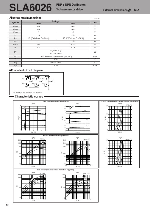
5 (Ta=25°C) 35 (Tc=25°C) 1000 (Between fin and lead pin, AC) 150 –40 to +150 3.57
sEquivalent circuit diagram
1
R1 R2
2
8 3
9 7 11 10
4
R3
6
5
12
R1: 2kΩ typ R2: 80Ω typ R3: 2kΩ typ
4.0 0.7 1.2 0.7 50 180
Characteristic curves
VCE(sat)-IB Temperature Characteristics (Typical)
NPN
3
θ j-a-PW Characteristics
PNP
(IC=–5A)
20
(IC=5A)
–3
2.5
75°C
–2.5
(Ta=25°C)
µA µA V
V V V µs µs µs µs MHz pF
µA mA V
V V V µs µs µs µs MHz pF
– – 0.6 2.0 1.5 50 100
VCC 24V, IC=6A, IB1=–IB2=12mA VCE=12V, IE=–1A VCB=10V, f=1MHz
VBE (V)
hFE-IC Characteristics (Typical)
NPN
20000 10000 5000
(VCE=4V)
20000
typ
PNP
(VCE=–4V)
PNP
–15
(VCE=–2V)
10000 5000
typ
irelay_60综合保护测控装置用户说明书 ()

iRelay 60综合保护测控装置用户说明书危险和警告本设备只能由专业人士进行安装,对于因不遵守本手册的说明所引起的故障,厂家将不承担任何责任。
重要提示感谢您使用深圳市中电电力技术股份有限公司的产品。
为了安全、正确、高效地使用本装置,请您务必注意以下重要提示:1) 本说明书仅适用于iRelay 60综合保护测控装置。
2) 请仔细阅读本说明书,并按照说明书的说明设置、测试和操作。
如有随机资料,请以随机资料为准。
3) 为防止装置损坏,严禁带电插拔装置各插件、触摸印制电路板上的芯片和器件。
4) 请使用合格的测试仪器和设备对装置进行试验和检测。
5) 装置如出现异常,请及时与本公司售后技术服务(400-8860-418)联系。
6) 本装置的设置缺省密码是:0000。
本说明书版权属深圳市中电电力技术股份有限公司所有,未经书面许可,不得复制,传播或使用本文件及其内容,违犯者将要对损坏负责。
深圳市中电电力技术股份有限公司保留所有版权。
我们已经检查了本手册关于描述硬件和软件保持一致的内容。
由于不可能完全消除差错,所以我们不能保证完全的一致。
本手册中的数据将定期审核,并在新一版的文件中做必要的修改,欢迎提出修改建议。
以后版本中的变动不再另行通知。
目录1 装置简介 (1)1.1 概述 (1)1.2 产品特点 (1)1.3 基本功能 (2)2 技术指标 (3)2.1 工作环境条件 (3)2.2 额定参数 (3)2.3 准确度 (3)2.4 遥信分辨率 (4)2.5 过载能力 (4)2.6 继电器输出 (4)2.7 开关量输入 (4)2.8 电气绝缘性能 (4)2.9 机械性能 (5)2.10 电磁兼容性能 (5)3 功能说明 (6)3.1 保护功能 (6)3.1.1 辅助元件 (6)3.1.2 大电流闭锁保护 (9)3.1.3 相电流充电保护 (10)3.1.4 相电流加速保护 (10)3.1.5 开入加速相电流保护 (11)3.1.6 速断保护 (11)3.1.7 限时速断保护 (12)3.1.8 过流保护 (13)3.1.9 过负荷保护 (14)3.1.10 反时限过流保护 (14)3.1.11 电压速断保护 (15)3.1.12 电压限时速断保护 (16)3.1.13 IN充电保护 (17)3.1.14 IN加速保护 (17)3.1.15 IN过流保护 (18)3.1.16 IN反时限过流保护 (19)3.1.17 I0充电保护 (19)3.1.18 I0加速保护 (20)3.1.19 I0过流保护 (20)3.1.20 I0反时限过流保护 (21)3.1.21 负序过流保护 (21)3.1.22 负序反时限保护 (22)3.1.23 电流不平衡保护 (22)3.1.24 过电压保护 (22)3.1.25 低电压保护 (23)3.1.28 VX低压保护 (25)3.1.29 高周保护 (25)3.1.30 低周保护 (26)3.1.31 功率保护 (26)3.1.32 同期检查 (27)3.1.33 重合闸功能 (29)3.1.34 绝缘监视 (31)3.1.35 起动间隔保护 (31)3.1.36 TV断线监视 (32)3.1.37 TA监视 (32)3.1.38 控制回路监视 (32)3.1.39 有效值过压保护 (33)3.1.40 有效值过流保护 (33)3.1.41 电动机运行状态判断 (34)3.1.42 起动时间过长保护 (35)3.1.43 过热保护 (35)3.1.44 tE时间保护 (36)3.1.45 堵转保护 (36)3.1.46 负荷丢失保护 (37)3.1.47 再起动功能 (37)3.1.48 起动次数保护 (38)3.1.49 开关量保护 (39)3.2 测量功能 (39)3.2.1 一次值 (39)3.2.2 二次值 (39)3.2.3 计量数据 (40)3.3 遥信功能 (40)3.4 控制功能 (40)3.5 通信功能 (40)3.6 记录功能 (41)3.6.1 事件记录 (41)3.6.2 故障录波记录 (42)3.6.3 波形瞬态捕捉功能 (42)3.6.4 起动报告功能 (43)3.7 对时功能 (43)4 操作使用说明 (47)4.1 装置前面板 (47)4.2 按键操作 (47)4.3 信号指示灯 (48)4.4 装置上电 (48)4.5 默认显示界面 (48)4.6 事件报告显示 (49)4.7 菜单说明 (49)4.7.3 定值设置 (53)4.7.4 报告管理 (59)4.7.5 装置维护 (61)4.7.6 装置调试 (62)4.7.7 定值清单 (62)5 安装调试说明 (74)5.1 安装 (74)5.1.1 装置安装图 (74)5.1.2 背板端子布置 (75)5.2 时钟电池 (78)5.3 通电试验 (78)5.4 投运前调试 (78)5.5 装置故障分析 (80)6 接线原理图 (82)6.1 装置接线示意图 (82)7 售后服务承诺 (87)7.1 装置升级 (87)7.2 质保范围 (87)7.3 售后联系方式 (87)1 装置简介1.1 概述iRelay 60是深圳市中电电力技术股份有限公司(以下简称中电技术)精心开发的,适用于中高压电压等级的新一代智能化微机综合保护测控装置。
DSEI60-06A;中文规格书,Datasheet资料

166 W
0.8...1.2 Nm
6
g
Symbol
IR
VF
VT0 rT RthJC RthCH trr IRM
Conditions
Characteristic Values typ. max.
VR = VRRM VR = 0.8·VRRM VR = 0.8·VRRM
TVJ = 25°C TVJ = 25°C TVJ = 125°C
IXYS reserves the right to change limits, test conditions and dimensions
© 2007 IXYS All rights reserved
/
0549
2-2
Dimensions TO-247 AD
C
D
t = 8.3 ms (60 Hz), sine
TC = 25°C mounting torque typical
Maximum Ratings
100 A 60 A
550 A 600
480 A 520Biblioteka 1510 A2s 1490
1150 A2s 1120
-55...+150 °C 150 °C
-55...+150 °C
Fast Recovery Epitaxial Diode (FRED)
DSEI60-06A DSEI60-06AT
IFAV = 60 A VRRM = 600 V trr = 35 ms
VRSM V
600 600
VRRM V
600 600
Type
DSEI 60-06A DSEI 60-06AT
A
SZ6010中文资料
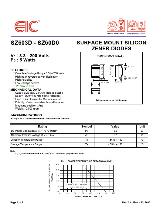
Fig. 1 POWER TEMPERATURE DERATING CURVE PD, MAXIMUM DISSIPATION (WATTS)
5.0 4.0 3.0 2.0 1.0 0 0 25 50 75 100 125 150 175 5.0 mm2 ( 0.013 mm thick ) copper land areash 25, 2005
SURFACE MOUNT SILICON ZENER DIODES
SMB (DO-214AA)
4 .8 ± 0 .1 5
5 .4 ± 0 .15
1.1 ± 0 .3
2.0 ± 0.1 3.6 ± 0.1 5 2.3 ± 0.2
0.22 ± 0.07
MECHANICAL DATA
* * * * * * Case : SMB (DO-214AA) Molded plastic Epoxy : UL94V-O rate flame retardant Lead : Lead formed for Surface mount Polarity : Color band denotes cathode end Mounting position : Any Weight : 0.093 gram
Dimensions in millimeter
MAXIMUM RATINGS
Rating at 25 °C ambient temperature unless otherwise specified
Rating
DC Power Dissipation at T L = 75 °C (Note1) Maximum Forward Voltage at I F = 1.0 A Junction Temperature Range Storage Temperature Range
电磁保护设备TeSys GV系列产品参数表说明书
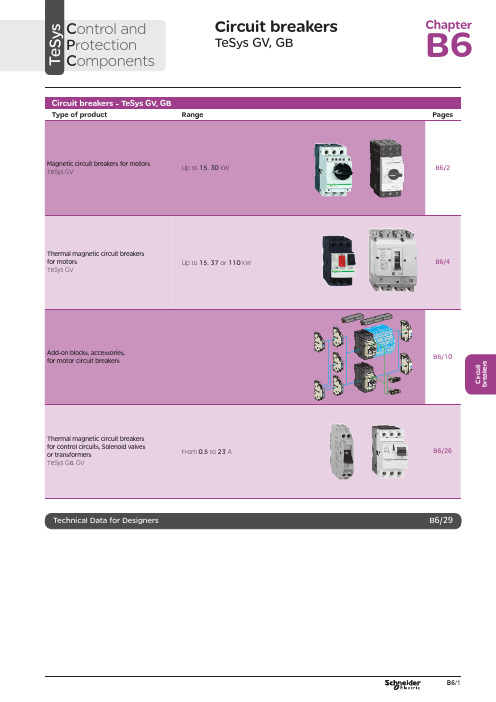
C i r c u i t b r e a k e r sCircuit breakersTeSys GV, GBC ontrol and P rotection C omponentsChapterB60.75g g 1.1g g 1.5375 2.533.5 LR2 K0308GV2LE071.1g g –––––– 2.533.5 LR2 K0308GV2LE071.5g g 1.5g g 3375451 LR2 K0310GV2LE08––– 2.2g g –––451 LR2 K0312GV2LE082.2g g 3501004375 6.378 LR2 K0312GV2LE103g g 410100 5.537510138 LR2 K0314GV2LE144g g 5.510100–––10138 LR2 K0316GV2LE14––––––7.537510138 LRD 14GV2LE14––––––937514170 LRD 16GV2LE165.515507.56751137514170 LR2 K0321GV2LE167.5155096751537518223 LRD 21GV2LE20915401147518.537525327 LRD 22GV2LE2211154015475–––25327 LRD 22GV2LE2215105018.54752237532416LRD 32GV2LE32(1) As % of Icu.g ) > 100 kA.GV2 LE10D F 526144.t i fC i r c u i t b r e a k e r s0.09––––––0.45LRD 03GV2L030.12g g –––0.37g g 0.638LRD 04GV2L040.18g g ––––––0.638LRD 04GV2L04––––––0.55g g 113LRD 05GV2L050.25g g ––––––113LRD 05GV2L05––––––0.75g g 113LRD 06GV2L050.37g g 0.37g g –––113LRD 05GV2L050.55g g 0.55g g 1.1g g 1.622.5LRD 06GV2L06–––0.75g g ––– 1.622.5LRD 06GV2L060.75g g 1.1g g 1.54100 2.533.5LRD 07GV2L07Example: GV3 L32 becomes GV3 L326.(1) As % of Icu. Associated current limiter or fuses, where required. See characteristics page B6/33.g > 100 kA.GV2 L10D F 526145.t i fGV3 L65D F 526146.t i fTeSys GVThermal-magnetic motor circuit breakers GV2 ME0.06gg––––––0.16…0.252.4GV2ME020.09g g––––––0.25…0.405GV2ME030.12 0.18g g g g – –– –– – 0.37 –g–g –0.40…0.638GV2ME040.25gg––– 0.55gg0.63…113GV2ME050.37 0.55 –g g –g g –0.37 0.55 0.75g g g g g g – 0.75 1.1– g g – g g 1…1622.5GV2ME060.75g g1.1gg1.5375 1.6...2.533.5GV2ME071.1 1.5g g g g 1.5 2.2g g g g 2.2 3 3 375 75 2.5 (4)51GV2ME082.2gg350100 43754...6.378GV2ME103 4g g g g 4 5.510 10100 100 5.5 7.5 3 375 756 (10)138GV2ME145.5 –15 –50 –7.5 – 6 –75 – 9 11 3 375 759…14170GV2ME167.5155096751537513…18223GV2ME209154011475 18.537517…23327GV2ME2111154015475 –––20…25327GV2ME22 (3)15105018.54752237524 (32)416GV2ME32Motor circuit breakers from 0.06 to 15 kW / 400 V, with lugsTo order thermal magnetic circuit breakers with connection by lugs, add the digit 6 to the end of reference selected above.Example: GV2 ME08 becomes GV2 ME086.Thermal magnetic circuit breakers GV2 ME with built-in auxiliary contact block With instantaneous auxiliary contact block (composition, see page B6/11):b GV AE1, add suffix AE1TQ to the motor circuit breaker reference selected above. Example: GV2 ME01AE1TQ .b GV AE11, add suffix AE11TQ to the motor circuit breaker reference selected above. Example: GV2 ME01AE11TQ .b GV AN11, add suffix AN11TQ to the motor circuit breaker reference selected above. Example: GV2 ME01AN11TQ .These circuit breakers with built-in contact block are sold in lots of 20 units in a single pack.(1) As % of Icu.(2) The thermal trip setting must be within the range marked on the graduated knob.(3) Maximum rating which can be mounted in enclosures GV2 MC or MP , please consult your Regional Sales Office. g > 100 kA.GV2 ME10D F 526134.t i fC i r c u i t b r e a k e r sTeSys GVTeSys protection componentsThermal-magnetic motor circuit breakers GV2 MEReferences0.06g g ––– 0.16…0.25 2.4GV2ME0230.09g g ––– 0.25…0.405GV2ME0330.120.18g g g g –––0.40…0.638GV2ME0430.250.37g g g g 0.37g g 0.63…113GV2ME0530.370.55g g g g 0.370.550.75g g g g g g 1…1.622.5GV2ME0630.75g g1.1g g 1.6…2.533.5GV2ME0731.11.5g g g g 1.52.2g g g g 2.5…451GV2ME0832.2g g 350100 4…6.378GV2ME10334g g g g 45.510101001006…10138GV2ME1435.515507.5675 9…14170GV2ME1637.515509675 13…18223GV2ME203911151540401147517…23327GV2ME2131115401547520 (25)327GV2ME223Contact blocksDescription Mounting Maximum number Type of contacts Sold in lots of Unitreference Instantaneous auxiliary contactsFront 1N/O + N/C 10GVAE113N/O + N/O 10GVAE203LH side2N/O + N/C 1GVAN113N/O + N/O1GVAN203AccessoryDescriptionApplicationSold in lots of Unitreference Cable end reducerFor connection of conductors from 1 to 1.5 mm 220LA9D99(1) For connection of conductors from 1 to 1.5 mm 2, the use of an LA9 D99 cable end reducer is recommended.(2) Maximum rating which can be mounted in enclosures GV2 MC or MP , please consult your Regional Sales Office (3) The thermal trip setting must be within the range marked on the graduated knob.g > 100 kA.GV2 ME pp 3D F 526135.t i fLA9 D99D F 533898.e p sTeSys GVReferencesTeSys protection componentsThermal-magnetic motor circuit breakersGV2 P, GV3 P and GV3 ME80GV2 P10D F 526137.t i fGV3 P65D F 526139.t i fGV3 P651D F 526140.t i fC i r c u i t b r e a k e r sTeSys GVReferences93610011181001581007.59707010010091150501001001115101010010012…20GV7RS20 2.0109113636100100111518181001001518.58810010015…25GV7RE25 2.0109117070100100111550501001001518.5101010010015…25GV7RS25 2.01018.53610018.522181810010022810025…40GV7RE40 2.01018.57010018.550100221010025…40GV7RS40 2.0102236100301810030810030…50GV7RE50 2.01522701003050100301010030 (50)GV7RS502.01537361004555181810010055810048...80GV7RE80 2.040377010045555050100100551010048...80GV7RS80 2.0404536100–1810075810060...100GV7RE100 2.0404570100–50100751010060...100GV7RS100 2.0405575353510010075903030100100901108810010090 (150)GV7RE1502.020557570701001007590505010010090110101010010090…150GV7RS150 2.02090110353510010011013216030303010010010016020088100100132…220GV7RE220 2.3509011070701001001101321605050501001001001602001010100100132…220GV7RS220 2.350(1) As % of lcu.TeSys protection componentsThermal-magnetic motor circuit breakers GV7 RGV7 RE40D F 526138.t i fGV7 RS220D F 526141.t i f0.12–0.120.180.18–0.370.40…0.6313GV2RT040.090.120.250.370.250.370.370.550.63…122GV2RT050.180.250.370.550.370.550.370.550.750.751.11…1.633GV2RT060.370.750.751.1 1.11.51.6…2.551GV2RT070.550.75 1.11.5 1.51.52.2 2.23 2.5…478GV2RT081.12.22.23344…6.3138GV2RT101.52.234445.5 5.57.56…10200GV2RT142.23 5.55.57.57.59119…14280GV2RT1647.57.5991513…18400GV2RT205.5911111118.517…23400GV2RT21(1) The thermal trip setting must be within the range marked on the graduated knob.GV2 RTD F 526142.t i fC i r c u i t b r e a k e r sblack handle, blue legend plate(1) The thermal trip setting must be within the range marked on the graduated knob.(2) Other accessories such as mounting, cabling and marking accessories are identical to those used for GV2 ME motor circuit breakers, see page B6/13.GV2 RTD F 526142.t i fD F 526340.e p sC i r c u i t b r e a k e r sTeSys GVDescription Mounting Maximum number Type of contacts Sold inlots of Unitreference Instantaneous auxiliary contactsFront (1)1N/O or N/C (2)10GVAE1N/O + N/C 10GVAE11N/O + N/O10GVAE20Side (LH)2N/O + N/C1GVAN11N/O + N/O1GVAN20Fault signalling contact + instantaneous auxiliary contact Side (3) (LH)1N/O (fault)+ N/O1GVAD1010+ N/C1GVAD1001N/C (fault)+ N/O1GVAD0110+ N/C1GVAD0101Short-circuit signalling contactSide (LH)1C/O common point1GVAM11(1 block on RH sideof circuit breaker GV2 ME)50 Hz GVAX11560 Hz GVAX116127 V60 Hz GVAX115220…240 V 50 Hz GVAX22560 Hz GVAX226380…400 V50 Hz GVAX38560 Hz GVAX386415…440 V 50 Hz GVAX415440 V60 Hz GVAX385Add-on contact blocksDescriptionMountingMaximum number Reference Visible isolation block (5)Front (1)1GV2AK00 (6)LimitersAt top(GV2 ME and GV2 P)1GV1L3Independent1LA9LB920(1) Mounting of a GV AE contact block or a GV2 AK00 visible isolation block on GV2 P and GV2 L .(2) Choice of N/C or N/O contact operation, depending on which way round the reversible block is mounted.(3) The GV AD is always mounted next to the circuit breaker.(4) To order an undervoltage trip: replace the dot (p ) in the reference with a U , example: GV AU025. To order a shunt trip: replace the dot (p ) in the reference with an S , example: GV AS025.(5) Visible isolation of the 3 poles upstream of circuit breaker GV2 P and GV2 L .Visible isolation block GV2 AK00 cannot be used with motor circuit breakers GV2 P32 and GV2 L32 (Ith max = 25 A).(6) Ie Max = 32 A.ReferencesTeSys protection componentsThermal-magnetic and magnetic motor circuit breakers GV2 with screw clamp connectionsAdd-on blocks and accessoriesCharacteristics:pages B6/89 and B6/94Dimensions, schemes:pages B6/70 to B6/82LA9LB920D B 126629.e p sC i r c u i t b r e a k e r sTeSys GVTerminal blockfor supply to one or more GV2 G busbar setsConnection from the top1GV1G09Can be fitted with current limiter GV1 L3 (GV2 ME and GV2 P)1GV2G05Cover for terminal block For mounting in modular panels10LA9E07Flexible 3-pole connection for connecting a GV2 to a contactor LC1-D09…D25 Centre distance between mounting rails: 100…120 mm10GV1G02Set of connections upstream/downstream For connecting GV2 ME to a printed circuit board 10GV2GA01“Large Spacing” adapter UL 508 type EFor GV2 P pp H7 (except 32 A)1GV2GH7Clip-in marker holders (supplied with each circuit breaker)For GV2 P , GV2 L, GV2 LE and GV2 RT (8 x 22 mm)100LA9D92ReferencesTeSys protection componentsThermal-magnetic and magnetic motor circuit breakers GV2 with screw clamp connectionsAccessoriesDimensions, schemes:pages B6/70 to B6/82D B 417942.e p sTeSys GVD B 126631.e p sD B 126630.e p sD B 126632.e p s7P B 106297_45.e p sExtended Rotary HandleAllows a circuit breaker or a starter-controller installed in back of an enclosure to be operated from the front of the enclosure.A rotary handle can be black or red/yellow, IP54 or IP65. It includes a function for locking the circuit breaker or the starter in the O (Off) or I (On) position(depending of the type of rotary handle) by means of up to 3 padlocks with a shank diameter of 4 to 8 mm. The extended shaft must be adjusted to use in different size enclosures. The IP54 rotary handle is fixed with a nut (Ø22) to make easierthe assembling. The new Laser Square tool brings the accuracy to align the circuit breaker and the rotary handle.device(padlocks not included)ReferencesTeSys protection componentsThermal-magnetic and magnetic motor circuit breakers GV2 with screw clamp connectionsC i r c u i t b r e a k e r sTeSys GVDescriptionMounting Maximum number Type of contacts Sold inlots of Unitreference Instantaneous auxiliary contactsFront1N/O or N/C (1)10GVAE1N/O + N/C 10GVAE11 (2)N/O + N/O10GVAE20 (2)Side (LH)2N/O + N/C1GVAN11 (2)N/O + N/O1GVAN20 (2)Fault signalling contact + instantaneous auxiliary contactFront 1N/O (fault)+ N/O1GVAED101 (2)N/O (fault)+ N/C1GVAED011 (2)Side (3) (LH)1N/O (fault)+ N/O1GVAD1010+ N/C1GVAD1001N/C (fault)+ N/O1GVAD0110+ N/C1GVAD0101Short-circuit signalling contact Side (LH)1C/O common point 1GVAM11(4)MountingVoltage ReferenceSide(1 block on RH side of circuit breaker)24 V 50 Hz GVA p 02560 Hz GVA p 02648 V 50 Hz GVA p 05560 Hz GVA p 05610050 Hz GVA p 107100…110 V 60 Hz GVA p 107110…115 V 50 Hz GVA p 11560 Hz GVA p 116120…127 V 50 Hz GVA p 125127 V 60 Hz GVA p 115200 V50 Hz GVA p 207200…220 V 60 Hz GVA p 207220…240 V 50 Hz GVA p 22560 Hz GVA p 226380…400 V 50 Hz GVA p 38560 Hz GVA p 386415…440 V 50 Hz GVA p 415415 V 60 Hz GVA p 416440 V 60 Hz GVA p 385480 V 60 Hz GVA p 415500 V 50 Hz GVA p 505600 V60 HzGVA p 505AccessoriesDescription Reference Sets of 3-pole 115 A busbars Pitch: 64 mm2 tap-off GV3 P pp and GV3 L pp GV3G2643 tap-off GV3 P pp and GV3 L pp GV3G364Cover “Large Spacing” UL 508 type E (Only one cover required on supply side)GV3 P ppGV3G66(1) Choice of N/C or N/O contact operation, depending on which way round the reversible block is mounted.(2) Contact blocks available in version with spring terminal connections. Add a figure 3 at the end of the references selected above. Example: GV AED101 becomes GV AED1013.(3) The GV AD pp is always mounted next to the circuit breaker.(4) To order an undervoltage trip: replace the dot (p ) in the reference with a U , example: GV AU025. To order a shunt trip: replace the dot (p ) in the reference with an S , example: GV AS025.Add-on blocks and accessoriesGV3 G66D F 537424.e p sTeSys GVD B 126637.e p sD B 126636.e p sD B 126632.e p s7P B 106297_45.e p sExtended Rotary HandleAllows a circuit breaker or a starter-controller installed in back of an enclosure to be operated from the front of the enclosure.A rotary handle can be black or red/yellow, IP54 or IP65. It includes a function for locking the circuit breaker or the starter in the O (Off) or I (On) position(depending of the type of rotary handle) by means of up to 3 padlocks with a shank diameter of 4 to 8 mm. The extended shaft must be adjusted to use in different size enclosures. The IP54 rotary handle is fixed with a nut (Ø22) to make easierthe assembling. The new Laser Square tool brings the accurency to align the circuit breaker and the rotary handle.For English 10-GVAPSEN For German 10-GVAPSDE For Spanish10-GVAPSES For Chinese 10-GVAPSCN For Portuguese 10-GVAPSPT For Russian 10-GVAPSRU For Italian10-GVAPSITD F 526342.e p sB6/21C i r c u i t b r e a k e r sTeSys GVfor locking the Start button (on open-mounted product)using up to 3 padlocks(padlocks to be ordered separately)External operator for mounting on enclosure door.Red Ø40 knob on yellow plate, padlockable in position O (with up to 3 padlocks). Door locked when knob in position I, and when knob padlocked in position O.GK3AP03(1) 1 voltage trip OR 1 fault signalling contact to be fitted inside the motor circuit breaker.Other versions24 to 690 V, 50 or 60 Hz voltage trips for circuit breakers GV3 ME80.Please consult your Regional Sales Office.ReferencesTeSys protection componentsMotor circuit breakers GV3 ME80 and GK3 EF80Add-on blocks and accessoriesCharacteristics:pages B6/89 and B6/92Dimensions:page B6/47B6/22D F 526344.e p sB6/23C i r c u i t b r e a k e r sTeSys GVThese allow remote indication of the circuit breaker contact states. They can be used for signalling, electrical locking, relaying, etc. They are available in two versions: standard and low level. They include a terminal block and the auxiliary circuits leave the circuit breaker through a hole provided for this purpose.They perform the following functions, depending on where they are located in the circuit breaker:Low levelGV7AB11Fault discrimination devicesThese make it possible to:b either differentiate a thermal fault from a magnetic fault,b or open the contactor only in the event of a thermal fault.VoltageReference a 24...48 and c 24…72 V GV7AD111 (1)z 110…240 VGV7AD112 (1)Electric tripsThese allow the circuit breaker to be tripped via an electrical control signal.b Undervoltage trip GV7 AUv Trips the circuit breaker when the control voltage drops below the tripping threshold, which is between 0.35 and 0.7 times the rated voltage.v Circuit breaker closing is only possible if the voltage exceeds 0.85 times the rated voltage. Circuit breaker tripping by a GV7 AU trip meets the requirements of IEC 60947-2.b Shunt trip GV7 ASTrips the circuit breaker when the control voltage rises above 0.7 times the rated voltage.b Operation (GV7 AU or GV7 AS)v When the circuit breaker has been tripped by a GV7 AU or AS, it must be reset either locally or by remote control. (For remote control, please consult your Regional Sales Office).v Tripping has priority over manual closing: if a tripping instruction is present, manual action does not result in closing, even temporarily, of the contacts.v Durability: 50 % of the mechanical durability of the circuit breaker.TypeVoltageReference Undervoltage trip48 V, 50/60 HzGV7AU055 (1)110…130 V, 50/60 Hz GV7AU107 (1)200…240 V, 50/60 Hz GV7AU207 (1)380…440 V, 50/60 Hz GV7AU387 (1)525 V, 50 HzGV7AU525 (1)Shunt trip48 V, 50/60 HzGV7AS055 (1)110…130 V, 50/60 Hz GV7AS107 (1)200…240 V, 50/60 Hz GV7AS207 (1)380…440 V, 50/60 Hz GV7AS387 (1)525 V, 50 HzGV7AS525 (1)(1) For mounting of a GV7 AD or a GV7 AU or AS.ReferencesTeSys protection componentsThermal-magnetic motor circuit breakers GV7 R with screw clamp connectionsAdd-on blocks and accessoriesCharacteristics:pages B6/51, B6/52 and B6/56Dimensions:pages B6/79 to B6/81Schemes:page B6/83B6/24B6/25C i r c u i t b r e a k e r sTeSys GVDescription ApplicationFor use on contactors Sold in lots of Unitreference Clip-on connectors for GV7 RUp to 150 A, 1.5…95 mm 2–3GV7AC021Up to 220 A, 1.5…185 mm 2–3GV7AC022Spreader 3-pole (1)To increase the pitch to 45 mm–1GV7AC03Terminal shields IP 405 (1)Supplied with sealing accessory–1GV7AC01Phase barriersSafety accessories used when fitting of shields is impossible –2GV7AC04Insulating screens Ensure insulation between the connections and the backplate –2GV7AC05Kits for combination with contactor (2)Allowing link between thecircuit breaker and the contactor. The cover provides protection against direct finger contactLC1 F115…F1851GV7AC06LC1 F225 and F2651GV7AC07LC1 D115 and D1501GV7AC08Replaces the circuit breaker front cover; secured by screws. It includes a device for locking the circuit breaker in the O (Off) position by means of up to 3 padlocks with a shank diameter of 5 to 8 mm (padlocks not included). A conversion accessory allows the direct rotary handle to be mounted on the enclosure door. In this case, the door cannot be opened if the circuit breaker is in the “ON” position. Circuit breaker closing is inhibited if the enclosure door is open.Description TypeDegree of protection Reference Direct rotary handleBlack handle, black legend plate IP 40GV7AP03Red handle, yellow legend plateIP 40GV7AP04Adapter plate (3)Four mounting direct rotary handle on enclosure doorIP 43GV7AP05Allows a circuit breaker installed in the back of an enclosure to be operated from the front of the enclosure. It comprises:b a unit which screws onto the front cover of the circuit breaker,b an assembly (handle and front plate) to be fitted on the enclosure door,b an extension shaft which must be adjusted (distance between the mounting surface and the door: 185 mm minimum, 600 mm maximum). It includes a device for locking the circuit breaker in the O (Off) position by means of up to 3 padlocks with a shank diameter of 5 to 8 mm (padlocks not included). This prevents the enclosure door from being opened.DescriptionTypeDegree of protection Reference Extended rotary handleBlack handle, black legend plate IP 55GV7AP01Red handle, yellow legend plateIP 55GV7AP02Allows circuit breakers not fitted with a rotary handle to be locked in the O (Off) position by means of up to 3 padlocks with a shank diameter of 5 to 8 mm (padlocks not included).Description ApplicationReference Locking deviceFor circuit breaker not fitted with a rotary handleGV7V01(1) Terminal shields cannot be used together with spreaders.(2) The kit comprises links, a protective shield and a depth adjustable metal bracket for the breaker.(3) This conversion accessory makes it impossible to open the door if the device is closed and prevents the device from being closed if the door is open.ReferencesTeSys protection componentsThermal-magnetic motor circuit breakers GV7 R with screw clamp connectionsAccessoriesGV7 AC07D F 537429.e p sGV7 AC08D F 537428.e p sDimensions:pages B6/79 to B6/81B6/260.5 6.63GB2DB051143GB2DB062263GB2DB073403GB2DB084503GB2DB095663GB2DB106833GB2DB1281083GB2DB14101383GB2DB16121653GB2DB20162203GB2DB21202703GB2DB22(1) Conforming to IEC 60947-1.GB2 CBppD F 526243.t i fGB2 CD ppD F 526244.t i fGB2 DBppD F 526245.t i fPresentation, selection :page B6/84Characteristics :pages B6/85 to B6/87Dimensions :page B6/88Schemes :page B6/88B6/27C i r c u i t b r e a k e r s(1) Conforming to IEC 60947-1.Accessories for circuit breakers GB2-CB, DB and CSDescriptionSold in lots of Unitreference Busbar set for supply to 10 GB2 DB or20 GB2 CB or GB2 CS with 2 connectors1GB2G210Supply connector 10GB2G01GB2 CS ppD F 526246.t i fPresentation, selection :page B6/84Characteristics :pages B6/85 to B6/87Dimensions :page B6/88Schemes :page B6/88B6/28B6/29B6/30TeSys GVCharacteristicsTeSys protection componentsMagnetic motor circuit breakers GV2 LE and GV2 LReferences:pages B6/2 and B6/3Dimensions:pages B6/43 to B6/47Schemes:page B6/48add-on contact blocks. Side by side mounting is possible up to 40 °C.(2) When mounting on a vertical rail, fit a stop to prevent any slippage.(1) As % of Icu.Average operating times at 20 °C related to multiples of the setting currentD F 534092.e p s1 3 poles from cold state2 2 poles from cold state3 3 poles from hot stateDynamic stressI peak = f (prospective Isc) at 1.05 Ue = 435 VD F 534093.e p s1 Maximum peak current2 32 A3 25 A4 18 A5 14 A6 10 A7 6.3 A8 4 A9 2.5 A 10 1.6 A11 Limit of rated ultimate breaking capacity on short-circuit of GV2 LE (14, 18, 23 and 25 A ratings).Dynamic stressI peak = f (prospective Isc) at 1.05 Ue = 435 VD F 534094.e p s1 Maximum peak current2 32 A3 25 A4 18 A5 14 A6 10 A7 6.3 A8 4 A9 2.5 A 10 1.6 A11 Limit of rated ultimate breaking capacity on short-circuit of GV2 LE (14, 18, 23 and 25 A ratings).Thermal limit in kA 2s in the magnetic operating zone Sum of I 2dt = f (prospective Isc) at 1.05 Ue = 435 V22Prospective Isc (kA)D F 534095.e p s1 32 A 2 25 A3 18 A4 14 A5 10 A6 6.3 A7 4 A8 2.5 A9 1.6 AThermal limit in kA 2s in the magnetic operating zone Sum of I 2dt = f (prospective Isc) at 1.05 Ue = 435 V22D F 534096.e p s1 25 A and 32 A 2 18 A3 14 A 4 10 A5 6.3 A6 4 A7 2.5 A8 1.6 AThermal limit in kA 2s in the magnetic operating zone Sum of I 2dt = f (prospective Isc) at 1.05 Ue = 435 V22D F 534097.e p s1 32 A (GV2 LE32)2 25 A and 32 A (GV2 L32)3 18 A4 14 A5 10 A6 6.3 A7 4 A8 2.5 A9 1.6 A10 Limit of rated ultimate breaking capacity on short-circuit of GV2 LE (14, 18, 23 and 25 A ratings).Average operating time at 20 °C without prior current flowx the setting current (Ir)D F 534098.e p s1 3 poles from cold state2 2 poles from cold state3 3 poles from hot stateA Thermal overload relay protection zoneB GV3 L protection zoneDynamic stressI peak = f (prospective Isc) at 1.05 Ue = 435 VProspective Isc (kA)D B 418280.e p s1 Maximum peak current2 GV3 L653 GV3 L504 GV3 L405 GV3 L326 GV3 L25Thermal limit in A 2sSum of I 2dt = f (prospective Isc) at 1.05 Ue = 435 V2Prospective Isc (kA)D B 418279.e p s1 GV3 L652 GV3 L503 GV3 L404 GV3 L325 GV3 L25TeSys GVDimensions, mountingD F 537440.e p sD F 537441.e p sD F 537444.e p sTeSys protection componentsMagnetic motor circuit breakers GV2 L and GV2 LETeSys GVDimensions, mounting TeSys protection componentsMagnetic motor circuit breakers GV2 L and GV2 LED B 127415.e p sD B 127414.e p sa b Mini Maxi Mini Maxi GV2 APN pp140250GV2 APN pp + GV APH02151250GV2 APN pp + GV APK11250434--GV2 APN pp + GV APH02 + GV APK11--250445TeSys GVDimensions,mounting Sets of busbars GV2 G445, GV2 G454, GV2 G472, with terminal block GV2 G05D F 537451.e p sGV2 G445224269314359GV2 G454260314368422GV2 G472332404476548D F 537452.e p sD F 537454.e p sGV2 G345 (3 x 45 mm)134GV2 G354 (3 x 54 mm)152TeSys protection componentsMagnetic motor circuit breakers GV2 L and GV2 LED F 537480.e psD F 537435.e p sD F 510637.e p sD F 510638.e p sD B 127416.e p sD B 127417.e p sa b Mini Maxi Mini Maxi GV3 APN pp189300--GV3 APN pp + GV APK12300481GV3 APN pp + GV APH03--200300GV3 APN pp + GV APH03 + GV APK12--300492TeSys GVSchemesTeSys protection componentsMagnetic motor circuit breakers GV2 L, GV2 LE, GV3 LD F 537474.e p sD F 537475.e p sD F 537476.e p sGV2 ME, GV2 P , GV3 ME, GV3 P and GV7 R motor circuit breakers are 3-pole thermal-magnetic circuit breakers specifically designed for the control and protection of motors , conforming to standards IEC 60947-2 and IEC 60947-4-1.Connection GV2GV2 ME and GV2 P circuit breakers are designed for connection by screw clamp terminals.Circuit breaker GV2 ME can be supplied with lugs or spring terminal connections.Spring terminal connections ensure secure, permanent and durable clamping that is resistant to harsh environments, vibration and impact and are even more effective when conductors without cable ends are used. Each connection can take two independent conductors.GV3GV3 circuit breakers feature connection by BTR screws (hexagon socket head), tightened using a n° 4 Allen key.This type of connection uses the Ever Link ® system with creep compensation (1) (Schneider Electric patent).This technique makes it possible to achieve accurate and durable tightening torque, in order to avoid cable creep.GV3 circuit breakers are also available with connection by lugs. This type of connection meets the requirements of certain Asian markets and is suitable for applications subject to strong vibration, such as railway transport.GV7GV7 circuit breakers: with connection by screw clamp terminals (for bars and lugs) and by clip-on connectors.OperationControl is manual and local when the motor circuit breaker is used on its own.Control is automatic and remote when it is associated with a contactor.GV2 ME and GV3 ME80Pushbutton control.Energisation is controlled manually by operating the Start button “I” 1.De-energisation is controlled manually by operating the Stop button “O” 2, or automatically by the thermal-magnetic protection elements or by a voltage trip attachment.GV2 P , GV3 P and GV7 Rb Control by rotary knob: for GV2 P and GV3 P b Control by rocker lever: for GV7 R.Energisation is controlled manually by moving the knob or rocker lever to position “I” 1.De-energisation is controlled manually by moving the knob or rocker lever to position “O” 2.De-energisation due to a fault automatically places the knob or rocker lever in the “Trip” position 3.Re-energisation is possible only after having returned the knob or rocker lever to position “O”.(1) Creep: normal crushing phenomenon of copper conductors, that is accentuated over time.GV2 MEwith screw clamp terminals124D F 526134.t i fGV2 MEwith spring terminals connections124D F 526135.t i fGV3 P1324D F 526136.t ifGV2 P1342D F 526137.t i fGV7 R132D F 526138.t i f。
- 1、下载文档前请自行甄别文档内容的完整性,平台不提供额外的编辑、内容补充、找答案等附加服务。
- 2、"仅部分预览"的文档,不可在线预览部分如存在完整性等问题,可反馈申请退款(可完整预览的文档不适用该条件!)。
- 3、如文档侵犯您的权益,请联系客服反馈,我们会尽快为您处理(人工客服工作时间:9:00-18:30)。
Maximum Reverse Leakage Current IR @ V R (V) (µA)
300 150 150 150 150 150 150 150 150 150 150 150 150 150 150 50 2.0 1.0 1.0 1.0 1.0 0.5 0.5 0.5 0.5 0.5 0.5 0.5 0.5 0.5 0.5 0.5 0.5 0.5 0.5 0.5 0.5 0.5 0.5 0.5 0.5 0.5 0.5 0.5 0.5 0.5 0.5 0.5 0.5 0.5 0.5 0.5 0.5 0.5 0.5 0.5 1.0 1.0 1.0 1.0 1.0 1.0 2.0 3.0 4.0 4.9 5.4 5.9 6.3 6.6 7.2 8.0 8.6 9.4 10.1 10.8 11.5 12.2 13.0 13.7 14.4 15.8 17.3 18.0 19.4 20.1 21.6 23.8 25.9 28.1 31.0 33.8 36.7 40.3 43.0 44.6 49.0 54.0 59.0 63.0 65.5 72.0 79.2 86.4 93.2 101 108 115 122 130 137 144
T L, LEAD TEMPERATURE ( °C)
Page 1 of 2
Rev. 03 : 25, 2005
元器件交易网
ELECTRICAL CHARACTERISTICS
Rating at 25 °C ambient temperature unless otherwise specified Nominal Zener Maximum Zener Voltage Impedance TYPE V Z @ IZT IZT Z ZT @ IZT ZZK @ IZK (V) (mA) (Ω) (Ω)
Page 2 of 2
Rev. 03 : March 25, 2005
Notes : ( 1 ) The type number listed have a standard tolerance on the nominal zener voltage of ± 10%, altered the fourth number of type from " 0 " for ± 10% tolerance to be " 5 " for ± 5.0% tolerance. ( 2 ) " SZ " will be omitted in marking on the diode.
Symbol
PD VF TJ Ts
Value
5.0 1.2 - 55 to + 150 - 55 to + 150
Unit
W V °C °C
Note : (1) T L = Lead temperature at 5.0 mm2 ( 0.013 mm thick ) copper land areas.
Dimensions in millimeter
MAXIMUM RATINGS
Rating at 25 °C ambient temperature unless otherwise specified
Rating
DC Power Dissipation at T L = 75 °C (Note1) Maximum Forward Voltage at I F = 1.0 A Junction Temperature Range Storage Temperature Range
元器件交易网
SZ603D - SZ60D0
VZ : 3.3 - 200 Volts PD : 5 Watts
FEATURES :
* Complete Voltage Range 3.3 to 200 Volts * High peak reverse power dissipation * High reliability * Low leakage current * Pb / RoHS Free
SZ603D SZ603G SZ603J SZ604D SZ604H SZ605B SZ605G SZ606A SZ606C SZ606I SZ607F SZ608C SZ608H SZ609B SZ6010 SZ6011 SZ6012 SZ6013 SZ6014 SZ6015 SZ6016 SZ6017 SZ6018 SZ6019 SZ6020 SZ6022 SZ6024 SZ6025 SZ6027 SZ6028 SZ6030 SZ6033 SZ6036 SZ6039 SZ6043 SZ6047 SZ6051 SZ6056 SZ6060 SZ6062 SZ6068 SZ6075 SZ6082 SZ6087 SZ6091 SZ60B0 SZ60B1 SZ60B2 SZ60B3 SZ60B4 SZ60B5 SZ60B6 SZ60B7 SZ60B8 SZ60B9 SZ60D0 3.3 3.6 3.9 4.3 4.7 5.1 5.6 6.0 6.2 6.8 7.5 8.2 8.7 9.1 10 11 12 13 14 15 16 17 18 19 20 22 24 25 27 28 30 33 36 39 43 47 51 56 60 62 68 75 82 87 91 100 110 120 130 140 150 160 170 180 190 200 380 350 320 290 260 240 220 200 200 175 175 150 150 150 125 125 100 100 100 75 75 70 65 65 65 50 50 50 50 50 40 40 30 30 30 25 25 20 20 20 20 20 15 15 15 12 12 10 10 8.0 8.0 8.0 8.0 5.0 5.0 5.0 3.0 2.5 2.0 2.0 2.0 1.5 1.0 1.0 1.0 1.0 1.5 1.5 2.0 2.0 2.0 2.5 2.5 2.5 2.5 2.5 2.5 2.5 2.5 3.0 3.0 3.5 3.5 4.0 5.0 6.0 8.0 10 11 14 20 25 27 35 40 42 44 45 65 75 75 90 125 170 190 230 330 350 380 430 450 480 400 500 500 500 450 400 400 300 200 200 200 200 200 150 125 125 125 100 75 75 75 75 75 75 75 75 100 110 120 130 140 150 160 170 190 210 230 280 350 400 500 620 720 760 760 800 1000 1150 1250 1500 1500 1650 1750 1750 1850 1850
Fig. 1 POWER TEMPERATURE DERATING CURVE PD, MAXIMUM DISSIPATION (WATTS)
5.0 4.0 3.0 2.0 1.0 0 0 25 50 75 100 125 150 175 5.0 mm2 ( 0.013 mm thick ) copper land areas.
SURFACE MOUNT SILICON ZENER DIODES
SMB (DO-214AA)
4 .8 ± 0 .1 5
5 .4 ± 0 .15
1.1 ± 0 .3
2.0 ± 0.1 3.6 ± 0.1 5 2.3 ± 0.2
0.22 ± 0.07
MECHANICAL DATA
* * * * * * Case : SMB (DO-214AA) Molded plastic Epoxy : UL94V-O rate flame retardant Lead : Lead formed for Surface mount Polarity : Color band denotes cathode end Mounting position : Any Weight : 0.093 gram
IZK (mA)
1.0 1.0 1.0 1.0 1.0 1.0 1.0 1.0 1.0 1.0 1.0 1.0 1.0 1.0 1.0 1.0 1.0 1.0 1.0 1.0 1.0 1.0 1.0 1.0 1.0 1.0 1.0 1.0 1.0 1.0 1.0 1.0 1.0 1.0 1.0 1.0 1.0 1.0 1.0 1.0 1.0 1.0 1.0 1.0 1.0 1.0 1.0 1.0 1.0 1.0 1.0 1.0 1.0 1.0 1.0 1.0
Maximum DC Zener Current IZM (mA)
1440 1320 1220 1100 1010 930 856 790 765 700 630 580 545 520 475 430 395 365 340 315 295 280 265 250 237 216 198 190 176 170 158 144 132 122 110 100 93.0 86.0 79.0 76.0 70.0 63.0 58.0 54.5 52.5 47.5 43.0 39.5 36.6 34.0 31.6 29.4 28.0 26.4 25.0 23.6