TLWW9900中文资料
Silvertel EvalAg9900评价板用户手册说明书
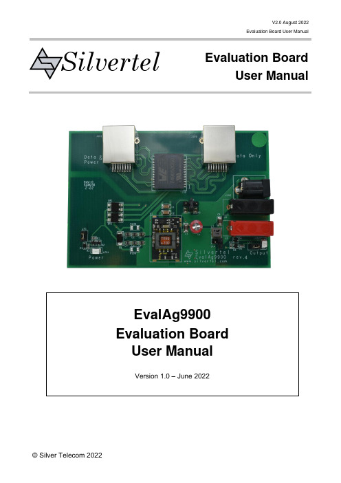
V2.0 August 2022Evaluation Board User ManualEvaluation BoardUser ManualSilvertelEvalAg9900 Evaluation Board User ManualVersion 1.0 – June 2022Table of Contents1Introduction (3)2Kit Contents (3)3Board Layout (3)Link Settings (3)Input Output Connections (3)4Compatible Models (4)5Input (4)Supply (4)Power LED (4)Operation (4)Class Programming (5)6Output (5)Output Voltage Adjust (5)Output Filter (5)Output LED (5)Output Power (5)Data Output (5)7EMI (6)8Test Setup (6)9Additional information (6)10Schematic (7)11Bill of Materials (8)Table of FiguresFigure 1: EvalAg9900 Board Layout (3)Figure 2: Basic Test Setup (6)1 IntroductionThis Manual is a guide to using the EvalAg9900 evaluation board fitted with one ofSilvertel’s Ag9900 ultra miniature PoE m odule with block or pin terminations for use in a wide variety of power over ethernet (PoE) applications. as such, it has been designed to pass through Ethernet data signals (10/100/1000/10GBASE-T) from the Midspan PSE (Power Sourcing Equipment) or PoE enabled switch connected to J101, onto the system connected to J100.2 Kit Contents➢ EvalAg9900 Evaluation Board➢ Ag9900 series Module Soldered to Evaluation Board3 Board LayoutFigure 1: EvalAg9900 Board LayoutLink SettingsLK1 – Power In LED LK2 – Output Adjust LK3 – Power Out LED LK4 – Pi filter bypassInput Output ConnectionsJ100 – RJ45 Data pass through J101 – RJ45 PoE connection J2– 2.5mm DC Load OutputJ3&J4 – Load OutputV2.0 August 2022Evaluation Board User ManualEvaluation BoardUser ManualSilvertel4 Compatible Models5 InputSupplyThe EvalAg9900 evaluation board can be powered using a compliant IEEE802.3af, or higher power, PoE PSE. The Power is extracted from the data pairsets using the LAN transformer T100. Data is then passively passed on to any peripheral equipment via J100, while the power is rectified to the correct polarity for the Ag9900 module using BR1 and BR2.Power LEDLED1 illuminates when the module is being supplied with greater than 36V. This can be disabled by removing the jumper link LK1, removing this link does not affect the power being delivered to the Ag9900.OperationTo ensure that the PSE does not apply power to a non-PoE enabled device the output port first checks for a valid PoE signature. If the PSE does not see a valid signature, then it will disconnect, wait approximately 2 seconds then try again.Once a valid signature has been detected the PSE may then perform classification to determine the power requirement of the PD, only after this has occurred will the PSE supply power to the powered device. Output Voltage(V)PackageVariantSMTAg9903MTB Low Profile SMT Ag9903LPB Low Profile DIL Ag9903LP Gull Wing SMT Ag9903MT Gull Wing SMTAg9903M SMTAg9905MTB Low Profile SMT Ag9905LPB Low Profile DIL Ag9905LP Gull Wing SMT Ag9905MT Gull Wing SMTAg9905M SMTAg9912MTB Low Profile SMT Ag9912LPB Low Profile DIL Ag9912LP Gull Wing SMT Ag9912MT Gull Wing SMTAg9912M SMTAg9924MTB Gull Wing SMT Ag9924MT Gull Wing SMTAg9924M351224Class ProgrammingThe Ag9900 is internally set to Class 0, to be supplied with the full IEEE802.3af power allocation. As such, the EvalAg9900 does not contain any Class programming circuitry.6 OutputOutput Voltage AdjustBy default, with no jumper present on LK2, the nominal output voltage of the fitted module will be present on the output connectors. This can be adjusted up or down by fitting a jumper to the adjust connector, LK2.The EvalAg9900 is fitted with two adjust resistors. The down adjust resistor R5 and the up adjust resistor R6, both are fitted with a 0Ω resistor for the maximum adjustment.To increase the output voltage the jumper should be positioned connecting the centre pin to the left pin of LK2, above R6.To decrease the output voltage the jumper should be positioned connecting the centre pin to the right pin of LK2, above R5.For configuring the output voltage to a user specific value, a different value resistor can be fitted in place of R5 or R6 to configure the module output the desired voltage. Contact Silvertel applications support for assistance selecting an appropriate value resistor.Output FilterThe EvalAg9900 is configured to Output filter B, see Ag9900 datasheet, when LK4 is not populated with a jumper. To change to Output Filter A, a jumper can be fitted to LK4, this will bypass the inductor in the pi filter, L7.See the relevant datasheet for more details, regarding the output filter.Output LEDLED2 illuminates when the module is outputting. This can be disabled by removing the jumper link LK3, removing this link does not affect the power being supplied by theAg9900.Output PowerThe output voltage will be present on both the 2.5mm DC connector, J2 and the banana plug terminals J3 and J4.J3 and the centre pin of J2 are the positive outputs, with the outer ring of J2 and J4 being the negative output.Data OutputAny data that is provided over the PI (Ethernet cable) connected to the Data & Power port, J101 will be transposed onto the Data output port, J100 via the data transformer.The data traces on the evaluation board have been designed to pass through10/100/1000/10GBASE-T Ethernet data signals. No processing or amplification of this signal will be performed on the evaluation board.7 EMIThe EvalAg9900 contains the recommended components for EMI filtering, see ANX-POE-EMI for more details.The board is fitted with ferrite beads, L1-6; if these are not required, they can be effectively removed from the circuit by fitting R108 and R109 with 0Ω resistors.8 Test SetupFigure 2 shows the basic set up using the EvalAg9900 evaluation board powered by Silvert el’s E valAg6120 PSE.The equipment required: -➢EvalAg9900 fitted with compatible Silvertel Ag99xx PD Module.➢EvalAg6120 or other IEEE802.3 compliant PSE➢Power supply unit, +44-57V output e.g. 60V bench power supply➢CAT5e or greater cables➢Application CircuitOptional equipment: -Data source e.g. PCFigure 2: Basic Test Setup9 Additional informationFull operating conditions and feature set can be found in the Ag9900 product datasheet, available from .10 Schematic11 Bill of Materials。
[基础培训]ATS9900产品介绍 ISSUE5.00
![[基础培训]ATS9900产品介绍 ISSUE5.00](https://img.taocdn.com/s3/m/cb6ae8e3102de2bd9605886a.png)
通过Sh接口共享HSS数据库
构造数据库
数据同步 数据同步
共享数据库
User Data
User Data
User Data
ATS
TAS
TAS
AS
AS
AS
HSS
HSS
IMS CORE
TAS 数据作为透明 数据存储在 HSS. 中
IMS CORE
每个AS都有自己的数据库会有很高的成
共享磁盘的数据库,节省 CAPEX
PES AS -- the PSTN/ISDN Emulation Subsystem AS PSS AS -- PSTN/ISDN Simulation Subsystem AS
Copyright © 2009 Huawei Technologies Co., Ltd. All rights reserved.
OCS Ro Rf CCF
ATS9900
SOAP
Sh
DNS
DNS Mr/Sr ISC NM
OMS
MRFP
MRFC
S-CSCF
Copyright © 2009 Huawei Technologies Co., Ltd. All rights reserved.
Page10
接口协议
接口
ISC Mr Sr Rf Ro Sh NM接口 BOSS接口
参考资料
HUAWEI ATS9900 通用语音业务服务器 产品手册 V100R003C00
Copyright © 2009 Huawei Technologies Co., Ltd. All rights reserved.
Page1
VW99000 2008.07 CN
2008年7月在部件开发范围内为提高效率而涉及的技术要求VW990 00 标准中心01 19 1共 37 页第1页翻译曹哲日期2010.02.11校对日期打字牛红珍日期2010.02.20 主题词:一般技术要求,样机审批手续,联邦全德事务所(BMG),部件开发,部件货运手册,坯块交付使用,开发,开发要求,开发条件,开发验收,设计验收,货运手册,计划验收前言本标准取代了VW 01154标准“开发条件;一般技术要求”本标准的主要辅助资料是VDA的“汽车VDA-部件货运手册”(www.vda-qmc.de);另一个辅助资料是模件第1卷“与部件货运手册搭接的技术”这样一来,本标准便能更清楚地阐明在部件开发范围内如何与一般技术联手提高工件的效率。
从这个意义上讲,一些工料,例如发动机机油、变速箱油、制动液或冷却液,都可以看作标准件来处理了。
VDA-模件第2卷“机械部件及电子部件货运手册”描绘了关于构件模件或部件开发方面的部件特殊技术要求,日后将要在大众汽车康采恩公司内部把常规的部件货运手册方案制定出来。
部件货运手册(BT-LAH)和本标准配合使用,是拓宽和提高委托人工作效率的基本条件。
以前版本VW 01154:1996-12,2000-06,2000-09,2001-05,2002-06,2003-12;VW90000:2006-10,2007-10,2008-05修订同VW 900 00 :2008-05标准比较,作了如下修改:—见附录A“修改的文献”目录1适用范围2设计参数概述2.1目标的确定2.2组织2.2.1 随时展望伴随研制发生的事情2.2.2 企业管理风险2.2.3 注意企业管理中的误区2.3下属承制厂的管理2.4生产过程和产品交货2.4.1 P-交货产品2.4.2 B-交货产品2.4.3 K-交货产品(奥迪)亦即E-交货产品(大众)2.4.4 样机审批2.4.5 首次样品验收2.5受法律保护的协议2.5.1 合伙者的责任2.5.2 关于康采恩的开发研制工作2.5.3 保护规则调查,第三者的保护规则2.5.4 工作接受人发明创造的报酬2.5.5 专利权、发明权和诀窍的区分2.5.5.1 信息的职责2.5.5.2 旧专利权2.5.5.3 版权2.5.5.4 全部有报酬的研制开发2.5.5.5 部分有报酬的开发2.5.5.5.1 独有的创新2.5.5.5.2 共同的创新2.5.5.5.3 与第三者联合行动2.6责任手册2.7改型品种管理2.8试验管理2.8.1 试验计划2.8.2 试验明细表2.8.3 试验记录2.9一般开发范围和供货范围2.10企业管理改革3方案设计的日程计划4报告收集与文献资料汇编4.1信息交流4.1.1 To-Do一览表(尚未解决的要点一览表) 4.1.2 会谈文献汇编4.2文献汇编责任和存档责任4.3文献的领先地位和现实性4.4汽车文献资料4.5可回逆性4.6零件标记4.6.1 成批生产的零件和原始零件4.6.2 试验零件和原型零件5产品外形设计的技术要求5.1质量贡献5.2质量管理系统5.3预防性QM-方法和风险保险5.3.1 误差的可能性和影响分析(FMEA)5.3.2 制造厂的设计、总装和维修(DfMAS) 5.3.3 容许误差的统计学分析法5.4供货链中的保险装置6产品可靠性和产品保证7 产品数据管理7.1 计算机辅助设计(CAD)技术要求7.2 DMU(数字式实体模型)-技术要求7.3 基准点系统和功能大小7.4 制图的技术要求8 环境的相容性8.1 一般要求8.2 回收再利用(材料)的技术要求8.3 材料的环境性能9 材料规格和表面9.1 材料的技术和戒律9.2 材料的技术要求9.3 耐气候性的技术要求9.4 电气元件的技术要求9.5 其他一般性技术要求9.6 表面保护、表层、棱边9.7 防腐蚀10 逻辑要求11 用户服务要求和维修要求11.1 用户服务11.2 原件12 标准零件和复式零件13 对工具和零件的要求13.1 工具13.1.1 试验工具和原型工具13.1.2 试验工具、原型工具和批量生产工具13.2 试验零件和原型零件14 定义、概念、缩写词14.1 概念14.2 缩写词15 参考文献附录A(供参考)修改文献1 适用范围这里说明的技术要求,适用于部件货运手册中全部订制的或委托的制品-部件、模件、组件或开发成果等等。
Signet 9900 H COMM Module Instruction Sheet说明书

*3-9900.094*For complete product information, please download the full 9900 Transmitter manual at Signet 9900 H COMM Module Instruction Sheet 3-9900.094 Rev. 4 05/18The H COMM Module enables communication between the 9900 and a HART ®-enabled device. The HART (H ighway A ddressable R emoteT ransducer) Protocol superimposes digital signals on top of the 4 to 20 mA analog signal.NOTE: With H COMM Module installed, a minimum of 24 V is required for loop-powered systems.EnglishInstallationIf the 9900 Base Unit will be mounted in a panel, plug-in modules may be installed either before or after the base unit is mounted.If the 9900 Base Unit will be mounted using the accessory wall mount kit (3-9900.392), install plug-in modules fi rst.If the Direct Conductivity/Resistivity Module or the 4 to 20 mA Output Module will be included in your unit, install the HCOMM module fi rst, then install the other module over the H COMM module To install the H COMM module, carefully align the module pins into its plug (see illustration) and push the module straight in until the tabs on the bottom edge snap into place.To uninstall, squeeze tabs, grasp the module and pull straight out.Wiring9900 Device ConnectionsLoop +Loop –Connecting HART with a Loop-powered sensor• English • Deutsch • Français • Español• Italiano • Português • 中文Georg Fischer Signet LLC, 3401 Aero Jet Avenue, El Monte, CA 91731-2882 U.S.A. • Tel. (626) 571-2770 • Fax (626) 573-2057For Worldwide Sales and Service, visit our website: • or call (in the U.S.): (800) 854-4090For the most up-to-date information, please refer to our website at 3-9900.094 Rev. 4 05/18© Georg Fischer Signet LLC 2018Loop +Loop –9900 Device ConnectionsConnecting HART to a Hand-Held Master DeviceHART ® is a registered trademark of the HART Communication Foundation, Austin, Texas, USA. Any use of the term HART hereafter in this document implies the registered trademark.Wiring continuedMfr. Part No. Code Description 3-9900.395159 001 697H COMM Module9900 Device ConnectionsConnecting HART to 9900 External PowerOrdering Information。
日锋9900说明书

R I F E N GRF9900变频调速器使用说明书哈尔滨市日锋电子有限责任公司序言感谢您选用哈尔滨市日锋电子有限责任公司的RF9900优化空间电压矢量PWM控制变频调速器。
本使用说明书为随机技术文件。
是您正确使用,安全运行的指导文件,请务必详细阅读和妥善保存。
为了充分发挥本产品的优越特性,确保使用者及设备的安全,在安装、调试、使用前,请认真阅读本使用说明书,详细了解变频器的安装,运行参数设定,安全注意事项,异常诊断及日常维护安全操作等事项。
请将此说明书交至实际使用者。
如在使用过程中,遇有疑难问题或特殊要求,请同本公司办事处或经销商联系,也可同本公司客户服务中心联系。
服务热线:800-8985852本使用说明书资料内容如有变更,恕不另行通知目录安全运行的注意事项 (5)1、验收 (6)1-1、检验 (6)2、安装 (7)2-1、选择安装变频器的环境 (7)2-2、安装空间选择 (8)2-3、安装尺寸 (9)3、接线 (10)3-1、外围设备和任选件的接线 (11)3-2、连接图 (12)3-3、主回路的接线 (13)3-4、接地 (17)3-5、控制电路的接线 (18)3-6、接线检查 (18)4、运行 (19)4-1、面板按键功能定义 (19)4-2、工作状态定义 (19)4-3、键盘使用 (19)4-4、变频器运行 (20)5、产品技术指标及规格 (22)6、功能参数表 (25)7、参数使用详细说明 (32)8、常见故障、异常现象及对策 (47)9、选件 (49)10、应用范例………………………………………..…………………….55. 附录附录1:定期维护及检查 (58)附录2:变频器适用上的注意 (60)附录3:电机适用上的注意............................ .. (62)附录4:周边设备适用上的注意......................... .. (64)安全运行的注意事项RF9900系列变频器 安装、运行、维护或检查之前要认真阅读本说明书。
PowerLite Pro Z9900WNL 3LCD 3-chip 项目器说明书
Large VenueSPECIFICATION SHEET3x Brighter Colors 1, and reliable performance — 3LCD, 3-chip technology One measurement of brightness is not enough — look for both high color brightness and high white brightness. The PowerLite Pro Z9900WNL has:Color Brightness: 9200 lumens 2White Brightness: 9200 lumens 2Widescreen performance — native WXGA (1280 x 800) resolution for presentations, videos, digital signage and moreSeven optional lenses with lens shift — including short-, wide-, rear- and long-throw lenses designed with a change-out lever for easy installationFlexible installation for an immersive experience in any setting — built-in Curved Edge Blending, Portrait Mode projection, and 360-degree installation Get twice the brightness and power — optional stackable frame makes it easy to install two projectors for unbelievable brightness, plus 3D support Versatile connectivity — supports the latest connectivity options, including HDBaseT™, HDMI™ and DVIDual-lamp design with lamp select/relay function — get both power savings and projector redundancy; includes an innovative liquid cooling system for added reliabilityPowerLite ®Pro Z9900WNL WXGA 3LCD ProjectorThe high-lumen, large-venue installation projector withwidescreen performance.Projector shown with lens.Lens sold separately.Large VenuePowerLite ® Pro Z9900WNL WXGA 3LCD ProjectorEPSON, EasyMP and PowerLite are registered trademarks, EPSON Exceed Your Vision is a registered logomark and Better Products for a Better Future is a trademark of Seiko Epson Corporation. PrivateLine is a registered trademark, FineFrame is a trademark and Epson Connection is a service mark of Epson America, Inc. SmartWay is a service mark of the U.S. Environmental Protection Agency. All other product and brand names are trademarks and/or registered trademarks of their respective companies. Epson disclaims any and all rights in these marks. Copyright 2014 Epson America, Inc. Com-SS-Oct-13 CPD-41395 6/14 Epson America, Inc.3840 Kilroy Airport Way, Long Beach, CA 90806Epson Canada Limited185 Renfrew Drive, Markham, Ontario L3R 6G3 www.epson.caInterfacesWireless LAN port: 802.11 b/g/n (optional – module sold separately)SpecificationsProjection System High-aperture Epson ®3-chip, 3LCD technologyProjection Method Front/rear/ceiling mountLCD Driving Method Epson Poly-silicon TFT Active Matrix Pixel Number 2,304,000 pixels x 3LCDs Color Brightness 2Color Light Output: 9200 lumens White Brightness 2White Light Output: 9200 lumensAspect Ratio Native 16:10, (supports 4:3, 16:9, 5:4)Native Resolution WXGA (1280 x 800)Contrast Ratio (Normal, Dynamic Mode) Up to 15,000:1Color Reproduction 1.07 billion colors Lamp TypeNormal:380 W x 2 UHE Portrait:304 W x 2 UHE Lamp Life 3Normal:Up to 4000 hours (ECO Mode)Up to 2500 hours (Normal Mode)Portrait:Up to 1000 hours (Normal Mode)Brightness Uniformity (typical) 90%Pixel Arrangement Cross stripeProjection LensScreen Throw Ratio Range 1.74 – 2.82 (standard lens)Size (projected distance) 60" – 500"Type Powered zoom/focusF-number 1.65 – 2.51 (standard lens), lens not included Focal Length 36 mm – 57.35 mm (standard lens)Zoom Ratio Optical zoom 1 – 1.61 (standard lens)Lens Shift (powered)Vertical: ±60%Horizontal: ±18%Keystone CorrectionVertical: -30 degrees to +30 degrees Horizontal: -30 degrees to +30 degreesVideoVideo StandardsAnalog: NTSC/NTSC4.43/PAL/M-PAL/N-PAL/PAL60/SECAM HDMI: 480i/576i/480p/576p/720p/1080i/1080p DVI-D: 480i/576i/480p/576p/720p/1080i/1080pVideo Processing 3D Y/C separation, 3D noise reduction, mosquito noise reductionDCDi ® – Directional Correlational DeinterlacingMotion-compensated Interlace-Progressive conversion (2:2, 3:2 film detection)Super ResolutionFineFrame™ interpolation 8:8 Pull-down processing Closed captioningNetworkingConnectivityWired: Integrated 100 MbpsWireless Security: WPA-PSK (TKIP/AES) / WPA2-PSK (TKIP/AES)E-mail Notification Via network Message Broadcasting SNMP Web Control Secure HTTPRemote Control and ManagementEasyMP ® Monitor, network projection, multi-projection, AMX ® Device Discovery, Crestron ® Integrated Partner and Crestron RoomView ®, Extron ® IP Link and XTP , PJLinkOther FeaturesOperating Temperature32 ° to 122 °F (0 ° to 50 °C) — Normal32 ° to 104 °F (0 ° to 40 °C) — Above 4900 feetPower Supply Voltage 100 – 240 V ±10%, 50/60 Hz AC Power Consumption 821 W (ECO Mode)995 W (Normal Mode)2.7 W standby (Communication on)0.26 W standby (Communication off)Fan Noise35 dB (ECO Mode)38 dB (Normal Mode)Security Kensington ®-style lock provision, anchor (metal) bar for security lock or cable, handles attached to body for cable wrapDimensions (W x D x H)Including Feet (with standard lens) 29.17" x 21.01" x 10.04"Excluding Feet (with standard lens) 29.17" x 21.02" x 7.76"Weight 58 lb with standard lensRemote ControlFeatures Brightness, contrast, tint, saturation, sharpness, input signal, sync, tracking, position, zoom, focus, lens shift, shutter, ID, source search, split screen Operating AngleFront:Right/left ± 60 degreesUpper/lower -45 to +15 degrees Rear:Right/left ± 60 degreesUpper/lower -40 to +15 degrees Operating Distance 98 ftECO FeaturesRoHS compliant Recyclable product 4Epson America, Inc. is a SmartWay SM Transport Partner 5SupportThe Epson Connection SMPre-sales support U.S. and Canada 800-463-7766Internet website Projector ProgramsThree-year projector limited warranty, 90-day limited lamp warranty, Epson Road Service Program and PrivateLine ®dedicated toll-free support (U.S. and Canada only)What’s in the BoxPowerLite Pro Z9900WNL projector, power cable, computer cable, projector remote control, batteries, user manual CD, Quick Setup Sheet, monitor and control CDOrdering Information Product Name Product Code PowerLite Pro Z9900WNL projectorV11H609920AccessoriesProduct CodeStandard zoom lens (ELPLS04) V12H004S04Long-throw zoom lens (ELPLL07)V12H004L07Middle-throw zoom lens 1 (ELPLM06)V12H004M06Middle-throw zoom lens 2 (ELPLM07)V12H004M07Rear-projection wide lens (ELPLR04)V12H004R04Wide zoom lens (ELPLW04)V12H004W04Short-throw zoom lens (ELPLU02) V12H004U02Mount Installation frame (ELPMB44) V12H681010Flush ceiling mount bracketV12H003B25Mount bracket with extended pipe V12H003B26False ceiling plate kit ELPMBP02Wireless LAN module V12H418P12Kensington security lockELPSL01Hardware remote control cable set V12H005C28Replacement remote control2157388Replacement lamp single (ELPLP81)V13H010L81Dual lamp kit (lamp x 2) (ELPLP82)V13H010L82Replacement portrait lamp single (ELPLP83) V13H010L83Dual lamp kit (lamp x 2) (ELPLP84)V13H010L84Replacement air filter set (ELPAF46)V13H134A461Compared to leading 1-chip DLP business and education projectors based on NPD data, July 2011 through June 2012. Color brightness (color light output) measured in accordance with IDMS 15.4. Color brightness will vary depending on usage conditions.2Color brightness (color light output) and white brightness (white light output) will vary depending on usage conditions. Color light output measured in accordance with IDMS 15.4; white light output measured in accordance with ISO 21118.3Lamp life will vary depending upon mode selected, environmental conditions and usage. Lamp brightness decreases over time.4See our website for convenient and reasonable recycling options at /recycle5SmartWay is an innovative partnership of the U.S. Environmental Protection Agency that reduces greenhouse gases and other air pollutants and improves fuel ef ciency.LANDVI-DRS-232CHDBaseTHDMIVideoS-VideoComputer RemoteMonitor Out BNCServicePowerWireless LAN Port Name EmailPhone Number。
西格奈特9900转发器说明书
*3-9900.090*Signet 9900 Transmitter3-9900.090 Rev 9 07/20English® instruments,, Conductivity/Resistivity,® Signal Converter required, sold separately). Panel MountOperating InstructionsField MountFlow515*/8510*, 525*, 2000,2100, 2507, 2536*/8512*,2537, 2540*, 2551, 2552, 258XpH/ORP2724-2726 with 27512734-2736 with 27512756-WTx–2757-WTx with3719 and 27512764-2767 with 27512774-2777 with 2751Conductivity/Resistivity, Salinity2819-2823 with2850 or Cond/Res Module2839-2842 with2850 or Cond/Res ModuleLevel, Temperature, Pressure2250*, 2350*, 2450*Dissolved Oxygen2610-51 direct to 9900* Can be run on Loop Power(see NOTE on page 11)• English• Deutsch• Français• Español• Italiano• 中文29900 Transmitter39900 Transmitter3-9900.393 Relay Module 49900 Transmitter59900 TransmitterVerify 9900 TransmitterNOTE:T he 4 to 20 mA Output,Direct Conductivity, andBatch Modules share thesame installation site onthe 9900 base units. 69900 Transmitter79900 Transmitter89900 Transmitter99900 Transmitter109900 TransmitterTechnical Notes:• See corresponding product manuals for maximum cable length.• Maintain cable shield through cable splice.Technical Notes:• Wiring terminals on the 2537 are rated for 16 to 22 AWG wires.• The cable must be7 mm to 10 mm in diameter (0.275 in. to 0.394 in.) to seal2551 Technical Notes:• When the blue jumper illustrated here is placed over both pins, the 2551-XX-11 (Blind Magmeter) outputsan open collector frequencyTechnical Notes:• The cable length from the 8058 to the 9900 must not exceed 60 m (200 ft).• When using the 8058-2, connect the loop source to Channel 1 input ONLY .• See the 8058 manual for more information.Wiring for:Signet 8058 i-Go™4-20 mA to S L ConverterO u t p u t S 3LS L OutputDATA GND SHLD V+8058-1close-upBlackRed ShieldWhite 8058-19900 S 3L Inputs0 8058-23 2 16 5 47 8 9Loop1PWRN/C S L DATALoop2PWR+GF+ SIGNETclose-up8058-2DATA GND V+SHLD BLACKWHITE RED 9900 S 3L InputsTechnical Notes:• Use three conductor shielded cable for sensor cable splices up to 305 m (1000 ft) max.• Maintain cable shield through cable splice.• Route sensor cable away from AC power lines.• Connect the silver (shield) wire to earth ground in case of EMI noise interference.Technical Notes:• The 2850 has no SHIELD wire.• To work correctly with the 9900, the 2850 must be set for the custom cell constant or the actual probe cell constant and the 9900 set for a 1.0 cell constant.Wiring for:* 2551-XX-21, -41Display Magmeter2250235024502551*27512850Black Red ShieldWhite V+DATA GND SHLD 9900 S 3L InputsNOTE: The 2850 has no SHIELD wire.Keypad FunctionsThe four buttons of the keypad are used to navigate display modes according to the descriptions in this table. Notice that the function of each button may change depending on the display mode.3sEditInput EditSaves ChangesInput Edit Choices(Password may be required)or ororSelect another Menu ItemReturn to View Mode+2x+OrThis basic operating procedure repeats throughout the 9900 program:1. Press ENTER for 3 seconds to enter MENU mode.2. Press ► to move to the desired menu then press ENTER to select it. (Password may be required.)3. Press ▲ or ▼ to select the desired menu item for editing.4. Press ► to edit the value/selection.5. Press ENTER to store the new value/selection.6. Press ▲ or ▼ to select another menu item if desired. Repeat steps 3-5 as required.7. Press ▲+▼ to select a di ff erent menu to edit. Repeat steps 2-5 as required.8. When fi nished editing all menus, press ▲+▼ again to return to normal operation.The menu is constructed in a loop, so you can move forward and backward to select an item. After any item is saved (by pressing ENTER), the display will return to the previous menu.System Setup: Menu NavigationINPUT MenuThis is the normal display and does not time out.。
色谱简单流程方框图
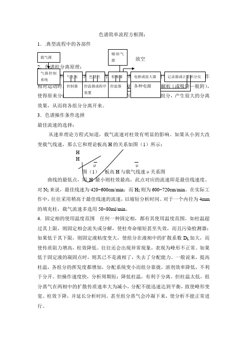
色谱简单流程方框图:1..典型流程中的各部件,效果,从而将各组分分离开来。
3.色谱操作条件选择最佳流速的选择:从速率理论方程式知道,载气流速对柱效有明显的影响。
如果从小到大改变载气线速,那么它和理论板高H的关系如图(1)所示:HHμμ图(1)板高H与载气线速μ关系图曲线的最低点,即H最小则柱效最高,此点对应的流速即是最佳线速度。
对N2来说,最佳线速为420~600cm/min;而H2则为600~720cm/min。
在实际工作中,往往采用稍高于最佳线速的流速,以缩短分析时间。
对于一个内径为4mm 的填充柱,载气流速多选用50~80ml/min。
4.固定相的使用温度范围任何一种固定相,都有其使用温度范围。
如柱温超过其上限,则固定相会流失或分解,使柱寿命缩短甚至失效,而且污染检测器;如果低于其下限,则固定液粘度变大,使组分在液相中的扩散系数D L加大,而使传质阻力增高,柱效降低。
往往还会出现异常现象,表现为峰形不正常。
如果低于固定液的凝固点时,则其已不是液相了,失去了分配能力。
一般说来,提高柱温,各组分的挥发度都增加,分配系统变小而组分靠拢,溶剂效率降低,不利于分开。
但操作速度快,分析周期短;降低柱温,有利于分离。
但柱温太低,组分蒸气在两相中的扩散传质速率大为减小,分配不能迅速达到平衡,致使峰形变宽、柱效下降,并延长分析时间。
甚至组分蒸气会冷凝下来,使分析不能正常进行。
5.汽化温度对气化温度的要求:应有足够的温度和热容量使被测试样瞬时汽化。
一般高于柱温50℃以上,或比样品中组分的最高沸点高出20~40℃;试样在该温度下,不被分解。
汽化温度不足的危害:峰形变宽、峰不对称,降低柱效及分离度;峰形异常,不能重复。
汽化温度过高的危害:样品分解,出现极为复杂的峰图,同样给以假象;汽化室橡皮垫变粘,易漏气;6.检测温度应保证样品组分蒸气不被冷凝,一般不低于柱温;要考虑检测器对温度的要求。
如火焰离子化检测器,温度不能低于100℃,防止水蒸汽冷凝,否则会破坏离子室的绝缘性,出现异常现象;要考虑温度对检测器灵敏度的影响,如热导检测器的温度高,则灵敏度降低。
- 1、下载文档前请自行甄别文档内容的完整性,平台不提供额外的编辑、内容补充、找答案等附加服务。
- 2、"仅部分预览"的文档,不可在线预览部分如存在完整性等问题,可反馈申请退款(可完整预览的文档不适用该条件!)。
- 3、如文档侵犯您的权益,请联系客服反馈,我们会尽快为您处理(人工客服工作时间:9:00-18:30)。
Document Number TELUX™ LEDDescriptionThe TELUX™ series is a clear, non diffused LED for high end applications where supreme luminous flux is required.It is designed in an industry standard 7.62 mm square package utilizing highly developed InGaN technology.The supreme heat dissipation of TELUX™ allows applications at high ambient temperatures.All packing units are binned for luminous flux and color to achieve best homogenous light appearance in application.Features•Utilizing InGaN technology •High luminous flux•Supreme heat dissipation: R thJP is 90 K/W •High operating temperature: T j + 100°C •Packed in tubes for automatic insertion•Luminous flux and color categorized for each tube •Small mechanical tolerances allow precise usage of external reflectors or lightguides•ESD-withstand voltage:> 1 kV acc. to MIL STD 883 D, Method 3015.7Applications• Exterior lighting • Interior lighting• Dashboard illumination• Replaces incandescent lampsParts TableAbsolute Maximum RatingsT amb = 25°C, unless otherwise specified TLWW9900PartColor, Luminous Intensity Angle of Half Intensity (±ϕ)TechnologyTLWW9900White, φV > 800 mlm45InGaN / Y AG on SiCParameterTest conditionSymbol Value Unit Reverse voltage I R = 10 µA V R 5V DC forward current T amb ≤ 50°C I F 50mA Surge forward current t p ≤ 10 µs I FSM 0.1A Power dissipation T amb ≤ 50°CP V 255mW Junction temperature T j 100°C Operating temperature range T amb - 40 to + 100°C Storage temperature range T stg - 55 to + 100°C Soldering temperaturet ≤ 5 s, 1.5 mm from body preheat temperature 100°C/ 30 sec.T sd260°CThermal resistance junction/ambientwith cathode heatsink of 70 mm2R thJA 200K/W Thermal resistance junction/pinR thJP90K/W Document Number 83216Optical and Electrical CharacteristicsT amb = 25°C, unless otherwise specifiedWhiteTLWW9900Chromaticity Coordinate Classificationtolerance ± 0.005ParameterTest conditionSymbol Min Typ.MaxUnit Total fluxI F = 50 mA,R thJA = 200°K/W φV 8001500mlm Luminous intensity/T otal flux I F = 50 mA,R thJA = 200°K/W I V /φV 0.8mcd/mlmColor temperature I F = 50 mA,R thJA = 200°K/W T K 5500K Angle of half intensity I F = 50 mA,R thJA = 200°K/Wϕ± 45deg Total included angle 90 % of T otal Flux Captured ϕ75deg Forward voltage I F = 50 mA,R thJA = 200°K/W V F 4.3 5.2V Reverse voltage I R = 10 µA V R 510V Junction capacitanceV R = 0, f = 1 MHzC j50pFGroupXYminmax min max 31a 0.29000.3025Y = 1.4x - 0.121Y = 1.4x - 0.07131b 0.30250.3150Y = 1.4x - 0.121Y = 1.4x - 0.07131c 0.29000.3025Y = 1.4x - 0.171Y = 1.4x - 0.12131d 0.30250.3150Y = 1.4x - 0.171Y = 1.4x - 0.12141a 0.31500.3275Y = 1.4x - 0.121Y = 1.4x - 0.07141b 0.32750.3400Y = 1.4x - 0.121Y = 1.4x - 0.07141c 0.31500.3275Y = 1.4x - 0.171Y = 1.4x - 0.12141d 0.32750.3400Y = 1.4x - 0.171Y = 1.4x - 0.12151a 0.34000.3525Y = 1.4x - 0.121Y = 1.4x - 0.07151b 0.35250.3650Y = 1.4x - 0.121Y = 1.4x - 0.07151c 0.34000.3525Y = 1.4x - 0.171Y = 1.4x - 0.12151d0.35250.3650Y = 1.4x - 0.171Y = 1.4x - 0.121Package Dimensions in mmDocument Number Ozone Depleting Substances Policy StatementIt is the policy of Vishay Semiconductor GmbH to1.Meet all present and future national and international statutory requirements.2.Regularly and continuously improve the performance of our products, processes, distribution andoperatingsystems with respect to their impact on the health and safety of our employees and the public, as well as their impact on the environment.It is particular concern to control or eliminate releases of those substances into the atmosphere which are known as ozone depleting substances (ODSs).The Montreal Protocol (1987) and its London Amendments (1990) intend to severely restrict the use of ODSs and forbid their use within the next ten years. Various national and international initiatives are pressing for an earlier ban on these substances.Vishay Semiconductor GmbH has been able to use its policy of continuous improvements to eliminate the use of ODSs listed in the following documents.1.Annex A, B and list of transitional substances of the Montreal Protocol and the London Amendmentsrespectively2.Class I and II ozone depleting substances in the Clean Air Act Amendments of 1990 by the EnvironmentalProtection Agency (EPA) in the USA3.Council Decision 88/540/EEC and 91/690/EEC Annex A, B and C (transitional substances) respectively. Vishay Semiconductor GmbH can certify that our semiconductors are not manufactured with ozone depleting substances and do not contain such substances.We reserve the right to make changes to improve technical designand may do so without further notice.Parameters can vary in different applications. All operating parameters must be validated for each customer application by the customer. Should the buyer use Vishay Semiconductors products for any unintended or unauthorized application, the buyer shall indemnify Vishay Semiconductors against all claims, costs, damages, and expenses, arising out of, directly or indirectly, any claim of personal damage, injury or death associated with such unintended or unauthorized use.Vishay Semiconductor GmbH, P.O.B. 3535, D-74025 Heilbronn, GermanyTelephone: 49 (0)7131 67 2831, Fax number: 49 (0)7131 67 2423 Document Number 83216。