Structure Analysis of ZnO Films Prepared by SILAR Method
Substrate effects of ZnO thin films prepared by PLD technique

Substrate effects of ZnO thin films prepared by PLD techniqueF.K.Shan,B.C.Shin,S.W.Jang,Y.S.Yu *Electronic Ceramics Center,Dongeui University,Busan 614-714,South KoreaAbstractZnO thin films are prepared on the glass,GaAs (100),Si(111),and Si(100)substrates at different temperatures by the pulsed laser deposition (PLD)method.X-ray diffraction (XRD)measurements indicate that the substrate temperatures of 200–500,200–500,300–500,and 300–500 C are the optimized conditions of crystalline for the glass,GaAs (100),Si (111),and Si (100)substrates,respectively.In spite of the films deposited on the different substrates,the films always show (002)orientation at the optimized conditions.Photoluminescence (PL)results indicate that the thin films fabricated at the optimized conditions show the intense near band PL emissions.The optimized conditions for PL are 500,500,400–500,and 500 C for glass,GaAs (100),Si (111),and Si (100)substrates,respectively.#2003Elsevier Ltd.All rights reserved.Keywords:Films;Optical properties;Substrate effects;X-ray methods;ZnO1.IntroductionSince the late eighties the pulsed laser deposition has been verified as a versatile technique for deposition of various materials including ferroelectrics,amorphous diamond and other ultra hard phases,polymers,com-pound semiconductors,and non-crystalline materials especially for metal oxide materials.1Among the several characteristics that distinguish PLD from other film growth techniques are its simplicity,the in-situ proces-sing of the multi-layer heteo-structures by using the multiple targets,and stoichiometric deposition etc.II–VI semiconductors are attractive in acoustic,electronic,and optical applications such as surface acoustic wave (SAW),acousto-optic,piezo-optic and photoelectric devices in particular,and voltage photophosphorescent devices.2ZnO is a novel photonic material with the properties similar to those of GaN.It has the direct band gap of 3.3eV at room temperature,the large exciton binding energy of 60meV,and the high melting temperature of 2248K.Since the wide applications of GaN,these properties similar to GaN make ZnO a potential candidate material for the optical devices such as light emitting diodes (LEDs)and laser diodes (LDs).So ZnO related materials have received considerable attentions in the recent years.3À6In order to develop ZnO thin films with high quality for devices with good performance,it is necessary to clarify the roles and the effects of additives,the different conditions of growth,and the substrate types.This will result in different microstructures suitable for the different applications.7À9Since ZnO thin films are highly c-axis oriented,the self-textured ZnO films can be synthesized easily on all sub-strates such as glass,GaAs,and Si etc.In this paper we report on the structural and optical properties of ZnO thin films fabricated on the glass,GaAs (100),Si(111),and Si(100)substrates at different temperatures by PLD technique.In this study,XRD and PL are used to eval-uate the temperature and the substrate effects on the properties of ZnO thin films,since it is essential to evaluate the film quality for the device applications.2.ExperimentIn the chamber of the PLD system,there are four target holders on one carousel and one substrate holder.The substrate holder is usually located at the opposite position to one of the target holders.KrF excimer laser (l =248nm, =25ns)is used for the ablation of the ZnO target at the energy density of about 1J/cm 2.The strong absorption of 248nm laser radiation by the tar-0955-2219/03/$-see front matter #2003Elsevier Ltd.All rights reserved.doi:10.1016/S0955-2219(03)00397-2Journal of the European Ceramic Society 24(2004)1015–1018/locate/jeurceramsoc*Corresponding author.E-mail addresses:ysyu@dongeui.ac.kr (Y.S.Yu),fkshancn@ (F.K.Shan).get produces an intense plasma plume in front of the target surface.The ablated material is then deposited on the substrate kept at50mm away from the target.The high purity ZnO powder(99.99%,Aldrich Chem. Co.,Inc)is used in the experiment.The disk-shaped specimen of10mm in diameter and2mm in thickness is obtained by the uniaxial pressing at100MPa,followed by the cold iso-static press at200MPa.The disk-like ZnO is sintered at600 C for2h and at1200 C for4h in order to condensate the target.In this study,the experi-ment conditions are as follows;the repetition frequency of the laser is5Hz,the deposition time is30min,the ambient O2pressure is200mTorr,and the temperature of the substrate varies from room temperature to600 C. The structures of ZnO thinfilms are studied by (XRD)measurements(D/MAX2100H,Rigaku,Japan, 40kV,30mA)using the Cu K a1radiation with l=1.54056A.PL measurements are carried out by the excitation of the He–Cd laser with325nm with an out-put power of30mW at room temperature.All optical measurements are performed in air as the reference.The emitting light from the sample is focused into the entrance slit of a spectrometer that has a spectral grat-ing of1200grooves/mm,and it is picked up by PMT.A cutofffilter is used to suppress the scattered laser radia-tion.The cutoffwavelength of thefilter at the ultraviolet side is about340nm.3.Results and discussionFig.1shows XRD patterns of ZnO thinfilms fabri-cated at different substrate temperatures(T s)on glass (A),GaAs(100)(B),Si(111)(C),and Si(100)(D)sub-strates.It is found that the substrate temperature T s plays an important role in determining the structure of ZnO thinfilms.To assess the quality of the thinfilms, the full width at half maximum(FWHM)is measured by omega scan and is shown in the insets of Fig.1(A),(B),(C), and(D),respectively.It is found that FWHM values of (002)ZnO at34.42 are around0.2 ,which means the high quality of the thinfilms fabricated by PLD.Fig.1(A)shows XRD patterns of ZnO thinfilms on the glass substrates.It is clear that thefilm deposited at T s higher than100 C has a polycrystalline structure, with(002)preferred orientation.While the thinfilm fabricated at room temperature has an amorphous nature.As T s is increased to500 C the preferred orientation of(002)shows a further increase in the peak intensity.It is found that FWHM increases atfirst,butit decreases with T s in the following,as shown in the inset of Fig.1(A).FWHM reaches its maximum when the thin film is fabricated at 200 C.While FWHM is correlated with the grain size D by Scherrer formula,10D ¼0:9l cos 0ð1Þl is the radiation wavelength, is the Bragg angle of (002)peak,and is FWHM value.From XRD results on the glass substrates,we conclude that T s of 200–500 C is good for crystalline.Fig.1(B)shows XRD patterns of ZnO thin films on GaAs (100)substrates.The thin film fabricated at room temperature shows the amorphous structure that is the same as the one on the glass substrate.The (002)orien-tation appears at the fabrication temperature of 100 C.The (002)orientation is enhanced when T s is increased from 100to 300 C.When T s surpasses 300 C,the film becomes clearly less oriented,with a resulting decrease in the (002)peak intensity.The variation of FWHM with T s is shown in the inset of Fig.1(B).The same behavior as the thin films on the glass substrates is found.One difference is that FWHMs of the thin films fabricated at 200,300,and 400 C are nearly the same.It is found that the fabrication temperature of 200–500 C is a good condition for crystal structures.Fig.1(C)and (D)show XRD patterns of ZnO thin films on Si (111)and Si (100)substrates,respectively.The (002)orientation in the thin films that are fabri-cated at high temperature and at low temperaturealmost disappears.The variations of FWHM on T s are shown in the insets of Fig.1(C)and (D).The same behavior as that on glass and on GaAs substrates is found in the thin films deposited on Si (111)and Si (100)substrates.In the case of Si (111)substrate,the thin film fabricated at the temperature of about 400 C shows the strongest diffraction peak,and simultaneously the lar-gest FWHM is observed in this thin film.It means the thin film fabricated at 400 C has the smallest grain size.In the case of Si (100)substrates,the thin films fabri-cated at 300–500 C show the intense diffraction peaks.The thin film fabricated at 400 C also exhibits the lar-gest FWHM.XRD results indicate that the c-axes of the grains become uniformly perpendicular to the substrate sur-face at the optimized temperatures.It is suggested that the surface energy of (002)plane is the lowest in the ZnO crystal.11Grains with the lower surface energy will become larger as the film grows.Then the growth orientation develops into one crystallographic direction of the lowest surface energy.This means that the (002)texture of the film may be easily formed.T s is crucial in that the low substrate temperature results in the low surface migration of adatoms,while the high substrate temperature causes the adatoms to re-evaporate from the film surface.The ZnO wurtzite structure makes the film grow in (002)preferred orientation on all substrates at the optimized growth temperature.Fig.2(A),(B),(C),and (D)shows the PL spectra of ZnO thin films on different substrates.Note that PL results of the thin films fabricated at roomtemperature,Fig.2.PL spectra of ZnO thin films fabricated at different temperatures on different substrates.F.K.Shan et al./Journal of the European Ceramic Society 24(2004)1015–10181017100,and600 C are not shown here.Fig.2(A)shows PL of ZnO thinfilms on the glass substrates.Near band emissions are found in all thinfilms,however,the intensity increases with T s.We have to mention here that the slit size of spectrometer for measuring the thin film fabricated at500 C is only1/5,1/6,and1/6com-pared with that for the thinfilm fabricated at400,300, and200 C,respectively.There are small broad green-yellow emissions in the thinfilms fabricated at200,300, and400 C.However,only a little green emission is observed in the thinfilm fabricated at500 C,which indicates its good quality.Fig.2(B)shows PL results from GaAs(100)sub-strates.The thinfilm fabricated at500 C shows the most intense near band emission without green one.The thinfilms fabricated at400,300,and200 C show small broad green and yellow emissions.The slit size of the spectrometer for the thinfilm fabricated at500 C is only1/20,1/20,and1/40compared with those of the thinfilms fabricated at400,300,and200 C,respec-tively.This result indicates that500 C is good for PL. PL results of the thinfilms deposited on Si(111)sub-strates are plotted in Fig.2(C).All ZnO thinfilms on Si (111)show the intense near band emissions.However, only the thinfilms fabricated at200and300 C show broad green emissions.The thinfilms fabricated at400 and500 C do not show green emissions,which means the good quality of the thinfilms.This indicates that the substrate temperature between400and500 C is the best condition for PL.From PL results of ZnO thinfilms on Si(100)sub-strate as shown in Fig.2(D),the strong near band with a little green emission are found in the thinfilms fabri-cated at200,300,and400 C,however,the green emis-sion of the thinfilm fabricated at500 C is invisible.As shown in Fig.2(D),the peak intensities of the thinfilms fabricated at300,400,and500 C are nearly the same. This indicates that the thinfilm fabricated at500 C is of good quality.4.ConclusionsZnO thinfilms are prepared on the glass,GaAs(100), Si(111),and Si(100)substrates at different temperatures by PLD method.XRD and PL are used to characterize ZnO thinfilms.XRD results indicate that the substrate temperatures of200–500,200–500,300–500,and300–500 C are the good conditions for crystalline for the glass,GaAs(100),Si(111),and Si(100)substrates, respectively.In spite of thefilms on the different sub-strates,thefilms always show(002)orientation at the optimized conditions.The thinfilms fabricated at the optimized condition show the intense near band PL emission.As results,the optimized conditions are500, 500,400–500,and500 C for the glass,GaAs(100),Si (111),and Si(100)substrates,respectively. AcknowledgementsThe authors would like to thankfinancial support by Electronic Ceramics Center(ECC)of Dongeui University founded by Korea Science and Engineer-ing Foundation(KOSEF),Ministry of Science and Technology(MOST)and Busan Metropolitan City Government.References1.Chrisey,D.G.and Hubler,G.K.,Pulsed Laser Deposition ofThin Films.Wiley,New York,1994.2.Vispute,R.,Talyansky,V.,Sharma,R.P.,Choopan,S.,Downes,M.,Venkatesan,T.,Li,Y.X.,Salamanca-Riba,L.G.,Iliad,A.A.,Jones,K.A.and McGarrity,J.,Advances in pulsed laserdeposition of nitrides and their integration with oxides.Appl.Surf.Sci.,1998,127/179,431–439.3.Shan,F.K.,Shin,B.C.,Kim,S.C.and Yu,Y.S.,Opticalproperties of As doped ZnO thinfilms prepared by pulsed laser deposition technique.J.Eur.Ceram.Soc.,2003,doi:10.1016/ S0955-2219(03)00489-8.4.Shan,F.K.and Yu,Y.S.,Band gap energy of pure and Al-doped ZnOfilms.J.Eur.Ceram.Soc.,2003,doi:10.1016/S0955-2219(03)00490-4.5.Look,D.C.,Recent advances in ZnO materials and devices.Mater.Sci.and Eng.,2001,B80,383–387.6.Han,J.,Senos,A.M.R.and Mantas,P.Q.,Varistor behavior ofMn-doped ZnO ceramics.J.Eur.Ceram.Soc.,2002,22,1653–1660.7.Makino,T.,Isoya,G.,Segawa,Y.,Chia,C.H.,Yasuda,T.,Kawasaki,M.,Ohtomo, A.,Tamura,K.and Koinuma,H., Optical spectra in ZnO thinfilms on lattice-matched substrates grown with laser-MBE method.J.Crystal Growth,2000,214/215, 289–293.8.Kim,K.J.and Park,Y.R.,Large and abrupt optical bandgap variation in In-doped ZnO.Appl.Phys.Lett.,2001,78, 475–477.9.Chen,Y.,Bagnall,D.and Yao,T.,ZnO as a novel photonicmaterial for UV region.Mater.Sci.Eng.,2000,B75,190–198. 10.Cullity,B.D.,Elements of X-ray Diffraction,2nd edition.Addi-son-Wesley Pub Co,1978.11.Chopra,K.L.,Major,S.and Pandaya,D.K.,Transparent con-ductors-a status review.Thin Solid Films,1983,102,1–46.1018 F.K.Shan et al./Journal of the European Ceramic Society24(2004)1015–1018。
溶胶-凝胶法制备ZnO薄膜

(AZO)thin films are emerging as an altemative potential candidate for ITO (Sn.doped In203)flims recently not only because of their comparable optical and electrical properties to ITO films,but also because of their higher thermal and chemical stability under the exposure to hydrogen plasma than ITO.
电子科技大学硕士学位论文
Abstract
Zinc oxide(ZnO)as a wide band-gap(3.3eV)compound semiconductor with
wurtzite crystal structure.is gaining importance for the possible application aS a semiconductor laser,due to its high exciton binding energy of 60 meV.A1·doped ZnO
Mn掺杂ZnO薄膜的软X射线发射光谱研究

Mn掺杂ZnO薄膜的软X射线发射光谱研究金晶;张新夷;周映雪【摘要】利用先进光源(ALS)8.0.1光束线的软X射线荧光谱仪,对采用分子束外延(MBE)设备在200℃下生长的Zn0.97Mn0.03O和Zn0.67Mn0.33O薄膜样品进行了电子结构的研究.根据共振和非共振Mn L2,3边的X射线发射光谱,计算出Mn L2与Mn L3发射峰相对积分强度的比值(I(L2)/I(L3)),可知样品的铁磁性与自由d 载流子的数目有关.在Zn0.97Mn0.03O中,Mn主要处于替代位置,并表现出较强的Coster-Kronig(C-K)跃迁效应,这说明样品中存在大量的自由d载流子.这些非局域的d载流子的行为类似于巡游电子,与Ruderman-Kittel-Kasuya-Yosid(RKKY)模型下计算得出的间隙Mn提供的4s电子,都可成为铁磁交换作用的媒介.在Zn0.67Mn0.33O中,自由d载流子的数目较少以及MnO团簇的存在是导致铁磁性向反铁磁性转变的主要原因.%The local electronic structures ofZn0.97Mn0.03O和Zn0.67Mn0.33O thin films prepared by a molecular beam epitaxy (MBE) at 200℃ were investigated by soft X-ray fluorescence spectrometer of beamline 8.0.1 of the Advanced Light Source (ALS). The special interest can be given to find the relationship between the electronic structure of Mn and magnetic properties of our samples. Analysis of the integral intensity ratio of Mn L2 to L3 emission lines(I(L2)//(L3)) from resonant and nonresonant Mn L2,3 X-ray emission spectra (XES) indicates that ferromagnet-ism (FM) is related to the free d charge carriers in the film. For ferromagnetic Zn0.97Mn0.03O sample, the majority of Mn atoms are incorporated at Zn substitutional sites and the film shows strong Coster-Kronig (C-K) transitions due to a large amount offree charge carriers available around Mn atoms. Both non-localized d charge carriers as itinerant electrons and 4s electrons from interstitial Mn obtained by Ruderman-Kittel-Kasuya-Yosid (RKKY) calculations can induce the ferromagnetic exchange interaction. However, the disappearance of FM in Zn0.67Mn0.33O sample can be explained in terms of the existence of MnO clusters leading to a reduction in the number of free charge carriers.【期刊名称】《无机材料学报》【年(卷),期】2012(027)003【总页数】5页(P296-300)【关键词】ZnO;X射线发射光谱;C-K跃迁;自由d载流子【作者】金晶;张新夷;周映雪【作者单位】上海大学材料科学与工程学院,上海200072;复旦大学应用表面物理国家重点实验室,上海200433;复旦大学应用表面物理国家重点实验室,上海200433;复旦大学应用表面物理国家重点实验室,上海200433【正文语种】中文【中图分类】O484稀磁半导体(DMSs)具有电子的电荷和自旋属性, 是目前自旋电子学领域内最典型的材料. 这种新型材料可以有效改善半导体器件中电子自旋的操纵[1-3]. 相关理论研究预言Mn掺杂p型ZnO DMSs的居里温度(TC)可以达到室温, 在实验中也观察到(Zn,Mn)O具有丰富的磁学现象[4-6]. (Zn, Mn)O磁性的多样性, 说明样品的磁性对制备方法和生长条件十分敏感[7-8]. 然而, 对其铁磁性是载流子诱导产生的, 还是源于 Mn相关的磁性第二相仍存在很大争议. 另外, 由于载流子的种类及浓度不同, 以及存在的缺陷等, 使得磁性的来源更加复杂.由于Mn掺杂ZnO的磁性与Mn原子和其邻近的原子以及周围的载流子之间的电子交换相互作用有关, 因此 Mn原子的局域环境以及电子结构对于了解(Zn,Mn)O 的磁性可以提供重要信息. 在本课题组最近的工作中[9], 利用软 X射线光谱并结合第一性原理研究发现, (Zn,Mn)O的铁磁性主要起源于替位Mn和间隙Mn之间的RKKY交换相互作用, 而RKKY作用与磁性离子的占位形式和巡游电子的数量有关. 本工作主要采用在共振和非共振激发条件下Mn L边的软X射线发射光谱(XES)和吸收光谱(XAS), 研究了样品的磁性与自由 d载流子之间的关系, 探讨了其磁性的起源.1 实验采用分子束外延(MBE)设备制备 Zn0.97Mn0.03O和 Zn0.67Mn0.33O薄膜样品. 生长条件、磁性和结构的分析可参考文献[10]. 前期研究发现, 在低Mn浓度样品中, Mn原子主要处于替代位置; 当Mn浓度较高(>20%)时, 在薄膜中会生成 MnO 团簇结构.随着 Mn浓度从低到高, 样品的磁性从铁磁(TC=45 K)向反铁磁发生转变. (Zn,Mn)O样品的软 X射线光谱的实验是在美国劳伦斯伯克利国家实验室(LBNL)的先进光源(ALS)8.0.1光束线(BL8.0.1)的软 X射线荧光(SXF)光谱仪上进行的. 样品的Mn L边XAS则在全电子产额模式(TEY)下通过测量样品的漏电流获得. Mn L 边XAS的测量是为了在Mn L边XES中选择合适的共振激发能量. 在共振和非共振的Mn L边XES测量中, 光谱仪的入射狭缝为 50 μm, 其对应的谱线的分辨率可达 0.6~0.8 eV. 入射光子与样品表面的角度为60°, 且发射光子的角度与入射光子的角度始终为90°. 测量谱图按照高度透明的金网栅检测到的落到样品表面的光子总数进行归一化. 全部实验均在室温下进行.2 原理2.1 软X射线光谱原理X射线与物质相互作用时, 激发和退激发过程如图1所示. X射线穿透物质时, 会被物质内部吸收.当 X 射线激发价带电子或芯电子, 使之成为光电子, 这种过程称为光电子发射(PES). 当芯能级电子吸收X射线能量跃迁到导带, 这种芯激发状态很不稳定, 可通过荧光(XES)或 Auger电子模式退激发.在X射线发射过程中, 如果芯电子被入射X射线共振激发到某吸收域附近, 其后退激发产生的发射谱强烈地依赖入射光能量, 这种发射谱称为共振X射线发射谱(RXES); 如果入射X射线能量远高于某吸收边时, 芯电子则被激发到连续的导带上, 这种发射谱为普通X射线发射谱(NXES).2.2 Coster-Kronig(C-K)跃迁Mn L2,3 X射线发射产生于从占据的3d4s价带态分别到2p3/2和2p1/2芯空穴的跃迁. 对于d轨道被完全占据的自由原子来说, Mn L2与Mn L3发射峰相对积分强度的比值(I(L2)/I(L3))仅取决于2p1/2和2p3/2能级电子数的统计分布. 当没有非辐射跃迁存在时,其比值应等于 1/2. 然而, 在固体中由于 2p芯空穴和未占据的3d电子之间静电相互作用, 比值会偏离1/2[11]. 在以上两种情况下, I(L2)/I(L3)可以提供价带中具有d对称性电子分布的信息. I(L2)/I(L3)的计算可以采用多重衰变过程来实现. 在这种模型中, 由X射线吸收产生的芯空穴可经由多种方式衰变: 辐射, 无辐射俄歇(Auger)和 Coster-Kronig(C-K)过程.如果电离空穴与填充空穴的电子在同一个主壳层内, 则称为C-K跃迁. 对于Mn掺杂的ZnO, 无辐射的L2L3M4,5 C-K跃迁可以影响其XES中I (L2)/I(L3)积分强度的比值. C-K过程发生的几率在自由原子中较小而在凝聚态体系中被增强. 这主要是由于在固体中原子间电子相互作用的屏蔽导致了无辐射C-K过程中初态和末态之间能量的减小, 这种效应在金属中表现得更加强烈.图1 X射线吸收, 光电子发射和荧光发射过程Fig. 1 X-ray absorption, photoelectron emission and fluorescence emission2 结果与讨论图2是Zn0.97Mn0.03O和Zn0.67Mn0.33O的Mn 2p XAS图谱. 640和651 eV附近的主峰主要由Mn 2p能级的自旋轨道劈裂而成. 谱线的多重态结构产生于2p5芯空穴和3d6电子之间的库仑及交换相互作用[12].从谱线特征可知两种样品的 Mn离子均为二价. 在Zn0.97Mn0.03O中, Mn处于替代位置并保持四面体对称性(Td); 而Zn0.67Mn0.33O的Mn 2p3/2和2p1/2吸收峰逐渐扩展并出现新特征(如箭头所示). 这主要是由于在高 Mn掺杂样品中形成八面体构型(Oh)的MnO团簇, 此时MnO已成为Mn的主要形态, 这与文献[10]的结果是一致的.为了获得有关占据的Mn 3d态的光谱信息, 在不同激发能量下测量了两种样品的Mn L2,3 XES,如图3所示. 所有光谱的特征强烈地依赖于激发能量和Mn浓度. 特征峰1为弹性峰. 特征峰2和3的双峰结构来源于Mn原子内3d能级之间的dd 激发,它是典型的到 3d5多重态的跃迁. 特征峰 4的宽峰结构对应于(Zn,Mn)O中非局域的配位O与Mn原子之间的电荷转移(CT)跃迁[13]. 其中, 低 Mn掺杂样品的CT峰比高Mn样品的更尖锐, 这主要是由于不同构型Mn2+和晶体场的相互作用的不同造成的. 当在高激发能下, 会出现L3和L2的荧光特征峰, 其发射能量并不随入射能量发生变化.图2 Zn0.97Mn0.03O和Zn0.67Mn0.33O的Mn 2p XAS图谱Fig. 2 Mn 2p XAS of Zn0.97Mn0.03O and Zn0.67Mn0.33O图3 不同激发能量下Zn0.97Mn0.03O和Zn0.67Mn0.33O的 Mn L2,3 XES图谱Fig. 3 Mn L2,3 XES of Zn0.97Mn0.03O (a) and Zn0.67Mn0.33O (b) at different excitation energies两种Mn掺杂ZnO的Mn L2 RXES和Mn L2 NXES如图4所示. 从图4 (a)看出, 与低Mn掺杂样品相比, 高掺杂样品的Mn L2发射峰处于较低的能量. 相同地, 在非共振激发下(图4 (b)), 样品Mn L3发射带劈裂成两个子带, 低能子带(637 eV)发射峰在高Mn样品中增强, 而高能子带(640 eV)发射峰在低Mn样品中较明显. Mn L3高能子带对应Mn 2p XAS最强吸收峰, 由于强烈的自吸收效应, 从而在高 Mn 样品中其高能发射峰强度大大降低[14]. 根据Mn 2p XAS和 Mn L2,3 XES结果, 可以认为, 在Zn0.67Mn0.33O中, 低能子带与Mn 3d-O 2p相互作用有关, 这主要产生于样品中形成的MnO第二相; 而在Zn0.97Mn0.03O中, 高能子带主要产生于Mn 3d态,它应该与Mn原子构型相关, 如替位Mn或间隙Mn.图4 Zn0.97Mn0.03O和Zn0.67Mn0.33O 的Mn L2 RXES和Mn L2,3 NXESFig.4 Mn L2 RXES (a) and Mn L2,3 NXES (b) of Zn0.97Mn0.03O andZn0.67Mn0.33O在(Zn,Mn)O中, Mn掺杂浓度对Mn及其邻近原子之间相互作用的影响也可以通过比较当激发能高于L2 吸收阈值时, Mn L2与Mn L3发射峰相对积分强度的比值(I(L2)/I(L3))来说明. 我们采用下面的公式来表示I(L2)/I(L3)[15],其中, f2,3是C-K跃迁几率, μ3/μ2是激发能量在L3和L2边光吸收系数的比值. 当激发能远高于 L2 边吸收阈值时, μ3/μ2比值为2. 此时, I(L2)/I(L3)仅由 f2,3决定, 而f2,3随元素中可以获得的自由d载流子的数目而增加[16]. 在共振激发下,μ3/μ2比值会随激发能而变化; 当激发在L2阈值时, 强烈的极化场导致其值迅速减小. 共振激发下的 I(L2)/I(L3)通常要比非共振激发时的大.I(L2)/I(L3)计算结果如表1所示. 在两种激发模式下, Zn0.97Mn0.03O的I(L2)/I(L3)比Zn0.67Mn0.33O的小, 这表明C-K跃迁在低Mn样品中被增强而在高Mn样品中被抑制. 在非共振激发下, I(L2)/I(L3)主要由f2,3决定. 因此, 我们可以认为在低Mn样品中具有大量的3d导带电子, 这些电子极大地贡献了自由电荷载流子的数目, 从而增强了 C-K跃迁的几率.对于共振激发下, 由于μ3/μ2的减小导致两种样品的I(L2)/I(L3)迅速增加.Singhal等[5]对Mn掺杂ZnO薄膜的磁性研究表明, 铁磁性产生于载流子诱导机制, 但并未指出非局域的自由电荷载流子对其铁磁性的贡献. 我们最近采用理论计算研究了在RKKY模型下, 不同Mn构型的交换相互作用与 Mn掺杂浓度的关系[9]. 理论计算研究表明, 在低Mn掺杂样品中, 替位Mn和间隙Mn原子之间的交换相互作用诱导了样品铁磁性的出现. 根据本文工作, 通过对 Mn L2,3 XES中I(L2)/I(L3)的进一步分析, 可知低Mn掺杂样品中存在大量的自由 d载流子. 可以认为在 Zn0.97Mn0.03O样品中, 适当的Mn浓度使得Mn-Mn距离满足了铁磁交换作用所需要的相邻Mn原子之间距离的要求;非局域的自由d载流子和间隙Mn原子提供的4s电子作为巡游电子而存在, 它们都可以成为铁磁交换作用的媒介. 在RKKY模型下, 磁性局域电子和巡游电子之间的交换相互作用使巡游电子发生自旋极化, 自旋极化随着局域电子的距离以震荡的方式衰减会导致两个近邻磁性离子之间产生间接超交换作用. 然而, 铁磁性样品的TC较低, 仅为45 K. 这主要是因为较低的巡游电子浓度所产生弱 RKKY交换相互作用造成的.表1 在共振和非共振激发下Zn0.97Mn0.03O和Zn0.67Mn0.33O的I(L2)/I(L3)Table 1 I (L2)/I(L3) intensity ratio of Zn0.97Mn0.03O andZn0.67Mn0.33O for the nonresonant and resonant excitationsSampleI(L2)/I(L3)RXES I(L2)/I(L3)NXES Zn0.97Mn0.03O 1.324 0.515Zn0.67Mn0.33O 2.055 0.706对于 Zn0.67Mn0.33O, 铁磁性开始向反铁磁性发生转变, 这与样品中反铁磁性耦合的 MnO团簇的出现有关. 一方面MnO是绝缘体, 其自由载流子浓度很低, 这限制了 Mn2+与载流子之间的相互作用,并最终阻碍了相邻Mn2+之间的铁磁交换.另一方面MnO又是一种典型的反铁磁材料. 因此, 通过控制Mn掺杂浓度, 改变了自由d电子的数目, 从而可以影响(Zn,Mn)O的磁性.3 结论主要采用Mn L边软X射线吸收和发射光谱对Zn0.97Mn0.03O和Zn0.67Mn0.33O的电子结构和磁性进行了研究. 通过光谱研究表明, Mn掺杂浓度对其在ZnO晶格中的占位形式和磁性起到十分重要的作用.在低Mn浓度时, Mn 原子主要处于替代位置, 样品表现出铁磁性; 对于高Mn浓度样品, MnO团簇已成为主要相, 并表现出强烈的反铁磁性. 结合 Mn L2,3 XES中对共振和非共振激发下I(L2)/I(L3)分析,可知在铁磁性样品中存在大量的自由 d载流子. 这些非局域的d载流子和RKKY模型下计算出的间隙Mn原子所提供的4s电子可以成为铁磁交换作用媒介的巡游电子. 在RKKY模型下, 相邻Mn 3d局域电子之间通过巡游电子产生间接交换作用是产生铁磁性耦合的主要原因. 因此, 软 X射线光谱提供了有关(Zn,Mn)O薄膜电子结构的重要信息, 这为分析DMSs的磁性创造了有利条件.参考文献:【相关文献】[1] Das Sarma S. A new class of device based on electron spin, rather than on charge, may yield dthe next generation of microelectronics. Am. Sci., 2001, 89(6): 516−523.[2] Bratkovsky A M. Spintronic effects in metallic, semiconductor, metal-oxide and metal-semiconductor heterostructures. Rep. Prog. Phys., 2008, 71(2): 026502.[3] Manyala N, DiTusa J F, Aeppli G, et al. Doping a semiconductor to created an unconventional metal. Nature, 2008, 454: 976−980.[4] Thakur P, Gautam S, Chae K H, et al. X-ray absorption and emission studies of Mn-doped ZnO thin films. Journal of the Korean Physical Society, 2009, 55(1): 177−182. [5] Singhal R K, Dhawan M S, Gaur S K, et al. Room temperature ferromagnetism in Mn-doped dilute ZnO semiconductor: an electronic structure study using X-rayphoto emission. J. Alloys Compd., 2009, 477(1/2): 379−385.[6] Kolesnik S, Dabrowski B. Absence of room temperature ferromagnetism in bulk Mn-doped ZnO. J. Appl. Phys., 2004, 96(9): 5379−5381.[7] Zhang J, Skomski R, Sellmyer D J. Sample preparation and annealing effects on the ferromagnetism in Mn-doped ZnO. J. Appl. Phys., 2005, 97(10): 10D303−1−3.[8] Wu Y, Rao K V, Wolfgang Voit, et al. Room temperature ferromagnetism and fast ultraviolet photoresponse of inkjet-printed Mn-doped ZnO thin films. IEEE Trans. Magn., 2010, 46(6): 2152−2155.[9] Jin J, Chang G S, Boukhvalov D W, et al. Element-specific electronic structure of Mn dopants and ferromagnetism of (Zn,Mn)O thin films. Thin Solid Films, 2010, 518(10): 2825−2829.[10] Xu W, Zhou Y X, Zhang X Y, et al. Local structures of Mn in dilute magnetic semiconductor ZnMnO. Solid State Commun., 2007, 141(7): 374−377.[11] Chang G S, Kurmaev E Z, Boukhvalov D W, et al. Clustering of impurity atoms in Co-doped anatase TiO2 thin films probed with soft x-ray fluorescence. J. Phys: Condens. Matter, 2006, 18(17): 4243−4251.[12] Fromme B, Brunokowski U, Kisker E, et al. d-d excitations and interband transitions in MnO: A spin-polarized electronenergy-loss study. Phys. Rev. B, 1998, 58(15): 9783−9792.[13] Butorin S M, Guo J H, Magnuson M, et al. Low-energy d-d excitations in MnO studied by resonant X-ray fluorescence spectroscopy. Phys. Rev. B, 1996, 54(7): 4405−4408. [14] Bartkowski S, Neumann M, Kurmaev E Z, et al. Electronic sturcture of titanium monoxide. Phys. Rev. B, 1997, 56(16): 10656−10667.[15] Kurmaev E Z, Ankudinov A L, Rehr J J, et al. The L2:L3 intensity ratio in soft X-ray emission spectra of 3d-metals. J. Electr. Spectr. Relat. Phenom., 2005, 148(1): 1−4.[16] Grebennikov V I. Surface Investigations: X-ray, Synchrotron and Neutron Techniques 11. 2002: 41.。
ZnO薄膜制备

Inverted Polymer Solar Cells Integrated with a LowTemperature-Annealed Sol-Gel-Derived ZnO Film as an Electron Transport Layer (溶胶凝胶法)
Preparation of the ZnO Precursor : The ZnO precursor was prepared by dissolving zinc acetate dihydrate (Zn(CH3COO)2·2H2O, Aldrich, 99.9%, 1 g) and ethanolamine (NH2CH2CH2OH, Aldrich, 99.5%, 0.28 g) in 2-methoxyethanol (CH3OCH2CH2OH, Aldrich, 99.8%, 10 mL) under vigorous stirring for 12 h for the hydrolysis reaction in air. Inverted solar cells were fabricated on ITO-coated glass substrates. The ITO-coated glass substrates were first cleaned with detergent, ultrasonicated in water, actone and isopropyl alcohol, and subsequently dried overnight in an oven. The ZnO precursor solution was spin-cast on top of the ITO-glass substrate. The films were annealed at 130 ° C, 150 ° C, or 200 ° C for 1 h in air. The ZnO film thickness was approximately 30 nm, as determined by a profilometer. The ZnO-coated substrates were transferred into a glove box.
2012文献报告

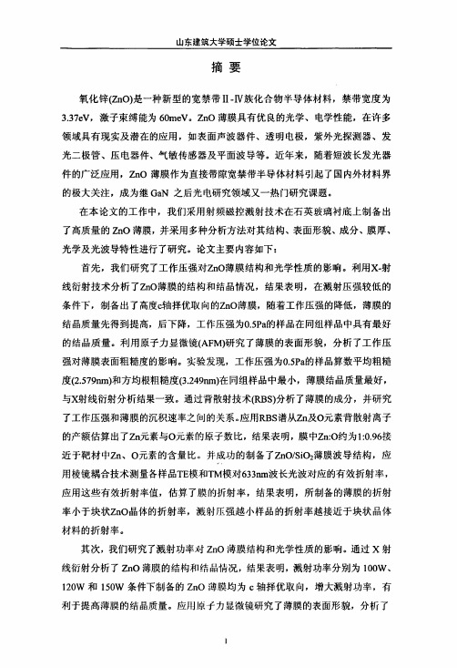
Fig.1. Variations of deposition rate ( ) and resistivity ( )of ZnO films deposited under 1--Ar,2--Ar+O2,3--Ar+H2 plasma for different RF power.
Fig.2. Variations of deposition rate ( ) and resistivity ( )of ZnO films deposited under 1--Ar,2--Ar+O2,and 3--Ar+H2 plasma for different chamber pressure.
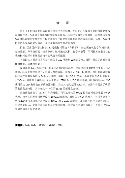
Fig.5. XRD spectra of the ZnO:Al films grown by RF magnetron sputtering under (a) Ar, (b) Ar+O2,and (c) Ar+H2 ambient.
• The crystallite size of ZnO films prepared under Ar,Ar+O2,and Ar+H2 gas ambient are 198,288,and 150 respectively as estimated from <002> peak (Table IV).
Thank you !
3.3 Optical properties
• The refractive index of ZnO:Al films deposited under Ar, Ar + O2, and Ar + H2 ambients at the optimum condition are given by 1.9, 2.1, and 1.5 respectively shown in Table III. • Generally, refractive index of ZnO:Al films can be represented by
ZnO薄膜晶体管的模型与新结构研究的开题报告

ZnO薄膜晶体管的模型与新结构研究的开题报告Title: Modeling and Characterization of ZnO Thin Film Transistors for Novel StructuresBackground:ZnO has attracted significant attention due to its high electron mobility and transparency, making it a promising material for use in thin film transistors (TFTs) for electronic applications. However, the poor thin film quality and surface roughness of ZnO have hindered its use in TFTs. Recently, novel structures have been proposed to improve the performance of ZnO TFTs.Objectives:The main objectives of this study are to:1. Develop a model for ZnO TFTs to investigate the impact of interface states, surface roughness, and trap density on device performance.2. Fabricate and characterize novel ZnO TFT structures, such as those incorporating nanocrystals or nanowires, to determine their potential advantages over traditional ZnO TFTs.3. Investigate the use of different gate dielectric materials to improve the electrical characteristics of ZnO TFTs.Methods:The modeling of ZnO TFTs will be carried out using device simulation software, while the novel structures will be fabricated using various deposition techniques, including physical vapor deposition and chemical vapor deposition. The electrical properties of the TFTs will be characterized using various methods, including current-voltage measurements and capacitance-voltage measurements.Expected Outcomes:The expected outcomes of this study are as follows:1. A better understanding of the critical factors affecting the performance of ZnO TFTs, including interface states, surface roughness, and trap density.2. Identification of the potential advantages of novel ZnO TFT structures over traditional ZnO TFTs, including increased mobility andbetter electrical properties.3. Improved electrical characteristics of ZnO TFTs through the useof different gate dielectric materials.Importance:The study of ZnO TFTs and their novel structures has importantimplications for the development of electronic devices, includingdisplays and sensors. ZnO TFTs have the potential to provide highperformance and low power consumption for these applications. This study will contribute to the development of more efficient and effectiveelectronic devices.。
ZnO薄膜的制备及其光学性质的研究
山东建筑大学硕士学位论文
关键词:ZnO薄膜,射频磁控溅射,光波导,X一射线衍射,c轴取向
山东建筑大学硕士学位论文
Preparation and Investigation of Optical Properties of ZnO Films
ABSTRACT
Zinc oxide(ZnO)is an important II-IV compound semiconductor with a wide direct band gap of 3.3eV at room temperature and a large excitation binding enery of 60meV.ZnO films have many realized and potential applications in many fields, such as surface acoustic wave devices,transparent electrodes,ultraviolet photodetectors,light emitting diodes,piezoelectric devices,gas sensors and planar optical waveguides,etc,due to their excellent optical and piezoelectric properties.In recent years,with widespread developing in short wavelength luminescent devices,
1物理中英文翻译
摘要由于ZnO材料在光电方面具有很多出色的特性,近年来已经成为光电材料研究领域内的佼佼者。
ZnO属于直接带隙宽禁带半导体,具有较大的激子束缚能,这些优点使得ZnO材料有望在紫外发光二极管和激光二极管等的研制中发挥重要作用。
另外,ZnO材料也适合制备纳米发电机、生物探测器及紫外探测器等。
目前,已出现的可以制备ZnO薄膜材料的技术有很多种,如金属有机化学气相沉积、磁控溅射、分子束外延、喷雾热解、脉冲激光沉积、化学水浴等,不同技术在制备ZnO 薄膜材料过程中都体现出特有的优势和局限性。
本篇论文主要采用不同技术制备了ZnO薄膜和ZnO基发光二极管,研究了薄膜和器件的性能。
具体内容如下:我们选取GaAs作为衬底,制备ZnO基同质结LED。
实验中利用MOCVD法生长n-ZnO 薄膜,经退火处理实现了n型向p型的转换,获得了p-ZnO:As薄膜。
然后利用磁控溅射技术在前期制备的p-ZnO:As薄膜上溅射一层ZnO籽晶层,再将带有ZnO籽晶层的p-ZnO:As薄膜置于容器中,采用水热法(CBD)生长ZnO纳米阵列。
测试结果显示,ZnO 基同质结LED表现出良好的整流特性。
当注入电流达到40mA时,该器件表现出了明显的电致发光特性,其中包含一个位于383nm的紫外发光峰。
我们选取蓝宝石(Al2O3)作为衬底,利用工业化的MOCVD设备在衬底上生长n-GaN薄膜,控制生长参数得到厚度为1500nm的薄膜。
而后在n-GaN薄膜上,利用等离子体增强MOCVD技术沉积一层厚度为500nm 的p-ZnO:N薄膜,并对器件进行了退火处理。
测试结果显示,此器件表现出明显的整流特性,电致发光光谱中出现了一个位于390nm 的强烈的紫外发光谱峰。
关键词:ZnO;GaAs;蓝宝石;MOCVD;CBDThe Preparation and Investigation of ZnO-based Lighting-emittingDiodeAbstractIn recent years, because ZnO material has many unique characteristics in photoelectric field, it has become the most high-profile material in the field of photoelectricity. ZnO possesses a wide and direct band gap. And at the same time, it also has a large exciton binding energy. These advantages make ZnO materials to be the expected material to prepare ultraviolet light-emitting diodes (LEDs).As a kind of indispensable exist, ZnO is a vital composition to produce UV LEDs and laser diode. ZnO material is also suitable for the preparation of nano generator, biological detector, ultraviolet laser tube and other advanced devices.Now, there are many technologies for preparation of ZnO thin film, such as metal organic chemical vapor deposition, magnetron sputtering technology, molecular beam epitaxy, spray pyrolysis, pulsed laser deposition, etc. Different technologies in the process of preparation of ZnO thin film materials have their unique advantages and disadvantages.In this paper, ZnO thin film and ZnO based LED are prepared by different technology, and the performances of ZnO films and ZnO based device are studied. Specific content is as follows:GaAs is used as a substrate of ZnO homojunction LED. n-ZnO thin film is deposited by MOCVD, the following step is annealing treatment to achieve the conversion of n to p type ,then the p-ZnO: As thin film is completed. And then using the magnetron sputtering technology to sputter a seed crystal layer on p-ZnO: As layer, the sample is put in a container. CBD method is conducted to grow ZnO nanometer array. The test results show that the device reveals good rectification characteristics. When injection current is set up to 40 mA, this device shows obvious electroluminescent characteristics with a strong ultraviolet spectrum peak at 383 nm. Selecting the sapphire (Al2O3) as substrate, and using industrialized MOCVD technique grows n-GaN film on the substrate. By controlling the growth parameters, a 1500 nm thin film is grown on sapphire. Using plasma enhanced MOCVD technique to deposit a p-ZnO: N thin layer with a thickness of 500 nm. And after the following step of annealing treatment, a heterojunction LED with a structure of p-ZnO:N/n-GaN:Si is achieved. Test results show that this device reveals obvious characteristics of rectification. The device shows a electroluminescent characteristics including a strong ultraviolet spectrum peak located at 390 nm.Key Words:ZnO;GaAs;sapphire;MOCVD;CBD图1-2 ZnO的纤锌矿结构图Fig.1-2. Schematic of wurtzite crystalline structure of ZnO表1-1 纤锌矿结构ZnO的物理参数Table.1-1. Characteristic parameters of wurtzite crystalline structured ZnO图2-1 溅射法原理示意图Fig.2.1 Schematic structure of Sputtering Method图2-2 利用水溶液法生长ZnO纳米棒工艺示意图Fig.2-2Schematic illustration of solution method growth mechanism图2-3 X射线衍射原理图Fig.2-3 Schematic structure of diffraction of X-ray图2.4 扫描电子显微镜(SEM)原理及结构示意图Fig.2.4 Schematic diagram and structure diagram of SEM图3-1 实验中所用的MOCVD示意图Fig.3.1 The diagram of MOCVD device applied in this experiment.图3-2 实验中所用的退火炉Fig.3.2 The diagram of Annealing furnace device applied in this experiment.图3-3 ZnO基同质结发光器件的结构示意图Fig.3-3Schematic diagram of ZnO-based homojunction LED图3-4(a) ZnO纳米墙的SEM侧视图Fig.3-4.(a) Cross SEM image of ZnO nanowalls图3-4(b) ZnO纳米墙的SEM俯视图Fig.3-4.(b)Top-view SEM image of ZnO nanowalls.图3-4(c) 1D-ZnO纳米棒/2D-ZnO:As薄膜结构的SEM侧视图Fig.3-4.(c)Cross SEM image of 1D-ZnO-nanorods/2D-ZnO:As film structure.图3-4(d) 1D-ZnO纳米棒的SEM俯视图Fig.3-4.(d)Top-view SEM image of 1D-ZnO-nanorods.图3-5 ZnO薄膜及其器件的XRD图谱。