SGTL5000_IIS DSP模式
C54x 系列DSP编程方法
汇编程序 汇编程序一般情况下主要包括下列文件:
• vectors.asm: 中断向量表 • example.asm: 主程序.asm文件 • C54x.h: 外围寄存器地址定义的头文件 • example.cmd: 链接命令文件 • example.pjt: 工程文件 • example.out: 程序的执行代码 •example.map: 代码生成工具生成输出的.map文件
2、在C语言中插入汇编语句 要点:使用asm语句将单行的汇编语言插入由编译器产 生的汇编语言文件,asm语句类似调用一个名为asm 的函数,语法格式如下: asm(“ assembler text”); 3、在程序中访问汇编语言变量 要点:a)使用.bss或.usect伪指令定义变量; b)使用.global伪指令将变量声明为外部变量; c)在汇编语言中,在变量名前加一下划线; d)在C中,将变量声明为外部变量,然后正常访问。
混合程序 汇编和C混合编程程序一般情况下主要包括下列文件: cvectors.asm:中断向量表 example_c.c:主程序.C文件 example_c.asm:主程序中调用的.asm文件 C54x _c.h:外围寄存器地址定义的C头文件 C54x.h:外围寄存器地址定义的头文件 example_c.cmd:链接命令文件 example_c.pjt:工程文件 example_c.out:程序的执行代码 example.map:代码生成工具生成输出的.map文件
编程实践
1、编写一个汇编程序控制实验台上的LED灯的亮 灭变化; (一种方法) 2、编写一个C程序控制实验台上的LED灯的亮灭 变化;(两种方法) 3、利用C和汇编的混合编程控制实验台上的LED 灯的亮灭变化。(一种方法)
克罗韦尔 Logix5000 控制系统中的 EtherNet IP 通信模块 说明书

Logix5000 控制系统中的 EtherNet/IP 通信模块产品目录号 5069-AENTR 、5069-AEN2TR用户手册原版说明书译文重要用户须知在安装、配置、操作或维护本产品之前,请阅读本文档以及“其他资源”章节所列的文档,了解关于安装、配置和操作该设备的信息。
除了所有适用的条例、法律和标准的要求之外,用户还必须熟悉安装和接线说明。
包括安装、调整、投入运行、使用、装配、拆卸和维护等在内操作必须由经过适当培训的人员根据适用的操作守则来执行。
如果未遵照制造商所指定的方式使用该设备,将可能导致该设备提供的保护失效。
对于由于使用或应用此设备而导致的任何间接损失或连带损失,罗克韦尔自动化公司在任何情况下都不承担任何责任。
本手册中包含的示例和图表仅用于说明。
由于任何具体的安装都存在很多差异和要求,罗克韦尔自动化对于依据这些示例和图表所进行的实际应用不承担任何责任和义务。
对于因使用本手册中所述信息、电路、设备或软件而引起的专利问题,罗克韦尔自动化公司不承担任何责任。
未经罗克韦尔自动化公司的书面许可,不得复制本手册的全部或部分内容。
在整本手册中,我们在必要的地方使用了以下注释,来提醒您注意相关的安全事宜。
设备表面或内部的标签提供特定的预防措施。
警告:标识在危险环境下可能导致爆炸,进而导致人员伤亡、物品损坏或经济损失的操作或情况。
注意: 标识可能导致人员伤亡、物品损坏或经济损失的操作或情况。
注意符号有助于您确定危险情况,避免发生危险,并了解可能的后果。
重要事项标识对成功应用和理解产品有重要作用的信息。
电击危险:位于设备 (例如,驱动器或电机) 表面或内部的标签,提醒相关人员可能存在危险电压。
灼伤危险: 位于设备 (例如,驱动器或电机) 表面或内部的标签,提醒相关人员表面可能存在高温危险。
弧闪危险:位于设备 (例如,电机控制中心) 表面或内部的标签,提醒相关人员可能出现闪弧。
闪弧可导致重伤或死亡。
佩戴适当的个人防护设备 (PPE)。
SGLT5000

SGTL5000Package3mm x 3mm 20 pin QFN5mm x 5mm 32 pin QFNCopyright © 2008 Freescale, Inc.All rights reserved.Freescale, Inc. makes no warranty for the use of its products, assumes no responsibility for any errors which may appear in this document, and makes no commitment to update the information contained herein. Freescale reserves the right to change or discontinue this product at any time, without notice. There are no express or implied licenses granted hereunder to design or fabricate any integrated circuits based on information in this document.SigmaTel and the SigmaTel logo are trademarks of Freescale, Inc. and may be used to identify Freescale products only. Windows Media and the Windows logo are trademarks or registered trademarks of Microsoft Corporation in the United States and other countries. Other product and company names con-tained herein may be trademarks of their respective owners.SGTL5000 1.ELECTRICAL SPECIFICATIONS1.1.Absolute Maximum RatingsExceeding the absolute maximum ratings shown in Table1 could cause permanentdamage to SGTL5000 and is not recommended. Normal operation is not guaran-teed at the absolute maximum ratings and extended exposure could affect long termreliability.Table 1. Absolute Maximum RatingsParameter Min Max Unit Storage Temperature-55125CMaximum Digital Voltage VDDD 1.98VMaximum Digital I/O Voltage - VDDIO 3.6VMaximum Analog Supply Voltage - VDDA 3.6VMaximum voltage on any digital input GND-0.3VDDIO+0.3VMaximum voltage on any analog input GND-0.3VDDA+0.3V1.2.Recommended Operating Conditions.Table 2. Recommended Operating ConditionsParameter Symbol/pin(S)Min Max Unit Ambient Operating Temperature Ta-4085CDigital Voltage (if supplied externally)VDDD 1.1 2.0VDigital I/O Voltage VDDIO 1.62 3.6VAnalog Output Supply VDDA 1.62 3.6VOperational SpecificationsTable 3. Audio PerformanceTest Conditions unless otherwise noted: VDDIO=1.8V, VDDA = 1.8V, Ta=25C, Slave mode, Fs = 48kHz, MCLK = 256Fs, 24 bit input.Parameter Min Typical Max UnitLine In Input Level.75VrmsLine In Input Impedance10k OhmLine In -> ADC -> I2S OutSNR (-60dB input)85dBSGTL5000Table 3. Audio PerformanceTest Conditions unless otherwise noted: VDDIO=1.8V, VDDA = 1.8V, Ta=25C, Slave mode, Fs = 48kHz, MCLK = 256Fs, 24 bit input.Parameter Min Typical Max Unit THD+N-70dBFrequency Response+/-.11dBChannel Separation79dBLine In -> Headphone_Lineout (CODEC Bypass Mode)SNR (-60dB input)98dBTHD+N (10k ohm load)-87dBTHD+N (16 ohm load)-87dBFrequency Response+/-.05dBChannel Separation (1kHz)82dBI2S In -> DAC -> Line OutOutput Level.6VrmsSNR (-60dB input)95dBTHD+N-85dBFrequency Response+/-.12dBI2S In -> DAC -> Headphone Out - 16 Ohm loadOutput Power17mWSNR (-60dB input)100dBTHD+N-80dBFrequency Response+/-.12dBI2S In -> DAC -> Headphone Out - 32 Ohm loadOutput Power10mWSNR (-60dB input)95dBTHD+N-86dBFrequency Response+/-.11dBI2S In -> DAC -> Headphone Out - 10k Ohm loadSNR (-60dB input)96dBTHD+N-84dBFrequency Response+/-.11dBPSRR (200mVp-p @ 1kHz on VDDA)85dBSGTL5000Table 4. Audio PerformanceTest Conditions unless otherwise noted: VDDIO=3.3V, VDDA =3.3V, Ta=25C, Slave mode, Fs = 48kHz, MCLK = 256Fs, 24 bit input. ADC tests were conducted with refbias = -37.5%, all other tests conducted with refbias = -50%Parameter Min Typical Max UnitLine In Input Level1VrmsLine In Input Impedance10k OhmLine In -> ADC -> I2S OutSNR (-60dB input)90dBTHD+N-72dBFrequency Response+/-.11dBChannel Separation80dBLine In -> Headphone_Lineout (CODEC Bypass Mode)SNR (-60dB input)102dBTHD+N (10k ohm load)-89dBTHD+N (16 ohm load)-87dBFrequency Response+/-.05dBChannel Separation (1kHz)81dBI2S In -> DAC -> Line OutOutput Level1VrmsSNR (-60dB input)100dBTHD+N-88dBFrequency Response+/-.12dBI2S In -> DAC -> Headphone Out - 16 Ohm loadOutput Power58mWSNR (-60dB input)98dBTHD+N-86dBFrequency Response+/-.12dBI2S In -> DAC -> Headphone Out - 32 Ohm loadOutput Power30mWSNR (-60dB input)100dBTHD+N-88dBFrequency Response+/-.11dBI2S In -> DAC -> Headphone Out - 10k Ohm loadSGTL50001.3.Timing Specifications1.3.1.Power Up TimingThe SGTL5000 has an internal reset that is deasserted 8 SYS_MCLK cycles after all power rails have been brought up. After this time communication can start..* 1uS represents 8 SYS_MCLK cycles at the minimum 8MHz SYS_MCLK.SNR (-60dB input)97dB THD+N-85dB Frequency Response+/-.11dB PSRR (200mVp-p @ 1kHz on VDDA)89dBTable 5. Power Up TimingSymbol ParameterMin TypicalMaxUnit TpcTime from all supplies powered up and SYS_MCLK present to initial communication1*uSTable 4. Audio PerformanceTest Conditions unless otherwise noted: VDDIO=3.3V, VDDA =3.3V, Ta=25C, Slave mode, Fs = 48kHz, MCLK = 256Fs, 24 bit input. ADC tests were conducted with refbias = -37.5%, all other tests conducted with refbias = -50%ParameterMin Typical MaxUnitFigure 1. Power Up TimingSGTL50001.3.2.I2CThis section provides timing for the SGTL5000 while in I2C mode (CTRL_MODE ==0).1.3.3.SPIThis section provides timing for the SGTL5000 while in SPI mode (CTRL_MODE ==1).Table 6. I2C Bus TimingSymbol ParameterMinTypicalMax Unit Fi2c_clk I2C Serial Clock Frequency 400kHz Ti2csh I2C Start condition hold time 150nS Ti2cstsu I2C Stop condition setup time150nS Ti2cdsu I2C Data input setup time to rising edge of CTRL_CLK 125nS Ti2cdh I2C Data input hold time from falling edge of CTRL_CLK (SGTL5000 receiving data)5nS Ti2cdh I2C Data input hold time from falling edge of CTRL_CLK (SGTL5000 driving data)360nS Ti2cclkl I2C CTRL_CLK low time 300nS Ti2cclkhI2C CTRL_CLK high time100nSTable 7. SPI Bus TimingSymbol ParameterMin Typical Max Unit Fspi_clk SPI Serial Clock Frequency ???MHz TspidsuSPI data input setup time10nSFigure 2. I2C Timing (CTRL_MODE == 0)SGTL50001.3.4.I2SThe following are the specifications and timing for I2S port. The timing applies to all formats.Tspidh SPI data input hold time 10nS Tspiclkl SPI CTRL_CLK low time ???nS Tspiclkh SPI CTRL_CLK high time ???nS Tccs SPI clock to chip select 60nS Tcsc SPI chip select to clock 20nS Tcsl SPI chip select low 20nS TcshSPI chip select high20nSTable 1-1.Symbol ParameterMin Typical Max Unit Flrclk Frequency of I2S_LRCLK ???96kHz FsclkFrequency of I2S_SCLK32*Flrclk, 64*FlrclkkHzTi2s_d I2S delay 10ns Ti2s_sI2S setup time10nsTable 7. SPI Bus TimingSymbol ParameterMin TypicalMaxUnit Figure 3. SPI TimingSGTL5000.Ti2s_hI2S hold time10nsTable 1-1.Symbol Parameter Min TypicalMaxUnit Figure 4. I2S Interface TimingSGTL50002.POWER CONSUMPTIONVDDD derived internally @ 1.2V, slave mode except for PLL case, 32 ohm load on HP , Conditions: -100dBFs signal input, slave mode unless otherwise noted, paths tested as indicated, unused paths turned off.A further 0.5-1.0mW reduction in power is expected with TA2 silicon.Table 8: Power Consumption: VDDA=1.8V , VDDIO=1.8VModeCurrent Consumption (mA)Power(mW)VDDDVDDA VDDIOPlayback (I2S->DAC->Headphone) 2.54.9 6.19Playback with DAP ((I2S->DAP->DAC->Headphone)3.59.98.08Playback/Record (I2S->DAC->Head-phone, ADC->I2S) 3.71 1.108.67Record (ADC->I2S)2.29 1.06 6.02Analog playback, CODEC bypassed (LINEIN->HP)1.48.89 4.27Standby, all analog power off .019.002.038Playback with PLL (I2S->DAC->HP)3.012.179.31Table 9: Power Consumption: VDDA=3.3V , VDDIO=3.3VModeCurrent Consumption (mA)Power(mW)VDDDVDDA VDDIO Playback (I2S->DAC->Headphone) 3.45.06711.60Playback with DAP ((I2S->DAP->DAC->Headphone)4.49.06715.03Playback/Record (I2S->DAC->Head-phone, ADC->I2S) 4.67.34316.53Record (ADC->I2S)2.90.29610.56Analog playback, CODEC bypassed (LINEIN->HP)1.91.039 6.43Standby, all analog power off.04.002.139Table 9: Power Consumption: VDDA=3.3V, VDDIO=3.3VModeCurrent Consumption (mA)Power(mW) VDDD VDDA VDDIOPlayback with PLL (I2S->DAC->HP) 3.92 2.7622.053.PINOUT & PACKAGE INFO3.1.Pinout3.2.Pin DescriptionTable 10. 20 pin QFN pinoutPin Name Description Notes PinCount1HP_R Right headphone output ANALOG 2HP_VGND Headphone virtual ground ANALOG 3VDDA Analog voltage POWER 4HP_L Left headphone output ANALOG 5VAG DAC VAG filter ANALOG 6LINEOUT_R Right line out ANALOG 7LINEOUT_L Left line out ANALOG 8LINEIN_R Right line in ANALOG 9LINEIN_L Left line in ANALOG 10MIC Microphone input ANALOG 11CPFILT Charge Pump Filter ANALOG 12VDDIO Digital I/O voltage POWER 13SYS_MCLK System master clock DIGITAL 14I2S_LRCLK I2S frame clock DIGITAL 15I2S_SCLK I2S bit clock DIGITAL 16I2S_DOUT I2S data output DIGITAL 17I2S_DIN I2S data input DIGITALDIGITAL 18CTRL_DATA I2C Mode: Serial Data (SDA);SPI Mode: Serial Data Input (MOSI)19CTRL_CLK I2C Mode: Serial Clock (SCL);DIGITALSPI Mode: Serial Clock (SCK)20VDDD Digital voltage POWER PAD GND Ground. Center PAD of package is ground connectionGROUNDfor part and must be connected to board ground.Table 11. 32 pin QFN pinoutPinPin Name Description Notes Count1GND Ground GROUND 2HP_R Right headphone output ANALOG 3GND Ground GROUND 4HP_VGND Headphone virtual ground ANALOG 5VDDA Analog voltage POWER 6HP_L Left headphone output ANALOG 7AGND Analog ground GROUND 8NC No connect DIGITAL 9NC No connect DIGITAL 10VAG DAC VAG filter ANALOG 11LINEOUT_R Right line output ANALOG 12LINEOUT_L Left line output ANALOG 13LINEIN_R Right line input ANALOG 14LINEIN_L Left line input ANALOG 15MIC Microphone input ANALOG 16MIC_BIAS Mic bias ANALOG 17NC No connect18CPFILT Charge pump filter ANALOG 19NC No connect20VDDIO Digital I/O voltage POWER 21SYS_MCLK System master clock DIGITAL 22NC No Connect23I2S_LRCLK I2S frame clock DIGITAL 24I2S_SCLK I2S bit clock DIGITAL 25I2S_DOUT I2S data output DIGITAL 26I2S_DIN I2S data input DIGITAL27CTRL_DATA I2C Mode: Serial Data (SDA);SPI Mode: Serial Data Input (MOSI)DIGITAL 28NC No connect29CTRL_CLK I2C Mode: Serial Clock (SCL);SPI Mode: Serial Clock (SCK)DIGITAL 30VDDD Digital voltage POWER31CTRL_ADR0_CS I2C Mode: I2C Address Select 0;SPI Mode: SPI Chip SelectDIGITAL32CTRL_MODE Mode select for I2C or SPI;When pulled low the control mode is I2C, when pulledhigh the control mode is SPIDIGITALPAD GND This PAD should be soldered to ground. This is asuggestion for mechanical stability but is not requiredelectrically.GROUNDTable 11. 32 pin QFN pinoutPinCountPin Name Description Notes3.3.PackageFigure 8. SGTL5000 5mmx5mm 32QFN Package (sheet 1)Figure 9. SGTL5000 5mmx5mm 32QFN Package (sheet 2)4.TYPICAL CONNECTION DIAGRAMSTypical connection diagrams are shown in this section that demonstrate the flexibil-ity of the SGTL5000. Both low cost and low power configurations are presentedalthough it should be noted that all configurations offer a low cost design with highperformance and low power.Some design considerations for SGTL5000 are as follows:•Star the ground pins of the chip, VAG ground, and all analog inputs/outputs to asingle point, then to the ground plane•Use the widest, shortest trace possible for the HP_VGND5.DEVICE DESCRIPTIONThe SGTL5000 is a low power stereo codec with integrated headphone amplifier. Itis designed to provide a complete audio solution for portable products needing line-in, mic-in, line-out, headphone-out, and digital I/O. Deriving it’s architecture frombest in class Freescale integrated products that are currently on the market, theSGTL5000 is able to achieve ultra low power with very high performance and func-tionality, all in one of the smallest footprints available. Target markets include por-table media players, GPS units and smart phones. Features such as caplessheadphone design and USB clocking mode (12MHz SYS_MCLK input) help loweroverall system cost.In summary, SGTL5000 accepts the following inputs:•Line input•Microphone input, with mic bias (mic bias only available in 32QFN version)•Digital I2S inputIn addition, SGTL5000 supports the following outputs:•Line output•Headphone output•Digital I2S outputThe following digital audio processing is included to allow for product differentiation:•Digital mixer•SigmaTel Surround•SigmaTel Bass Enhancement•Tone Control, parametric equalizer, and graphic equalizerThe SGTL5000 can accept an external standard master clock at a multiple of thesampling frequency (i.e. 256*Fs, 385*Fs, 512*Fs). In addition it can take non stan-dard frequencies and use the internal PLL to derive the audio clocks. The devicesupports 8kHz, 11.025kHz, 16kHz, 22.5kHz, 24kHz, 32KHz, 44.1kHz, 48kHz,96kHz sampling frequencies.5.1.System Block Diagram w/ Signal Flow and Gain MapFigure10 below shows a block diagram that highlights the signal flow and gain mapfor the SGTL5000.Figure 10. System Block Diagram, signal flow and gainTo guarantee against clipping it is important that the gain in a signal path in additionto the signal level does not exceed 0dB at any point.5.2.PowerThe SGTL5000 has a flexible power architecture to allow the system designer tominimize power consumption and maximize performance at the lowest cost.5.2.1.External Power SuppliesThe SGTL5000 requires 2 external power supplies: VDDA and VDDIO. An optionalthird external power supply VDDD may be provided externally to achieve lowerpower. A description for the different power supplies is as follows:•VDDA: This external power supply is used for the internal analog circuitryincluding ADC, DAC, LINE inputs, MIC inputs, headphone outputs and refer-ence voltages. VDDA supply ranges are shown in section 1.2. A decouplingcap should be used on VDDA as shown in the typical connection diagram insection 4.•VDDIO: This external power supply controls the digital I/O levels as well as the output level of LINE outputs. VDDIO supply ranges are shown in section 1.2. Adecoupling cap should be used on VDDIO as shown in the typical connectiondiagram in section 4.Note that if VDDA and VDDIO are derived from the same voltage, a single decou-pling capacitor can be used to minimize cost. This capacitor should be placed clos-est to VDDA.•VDDD: This is a digital power supply that is used for internal digital circuitry. Fora low cost design, this supply can be derived from an internal regulator and noexternal components are required. If no external supply is applied to VDDD, theinternal regulator will automatically be used. For lowest power, this supply canbe driven at the lowest specified voltage given in section 1.2. If an external sup-ply is used for VDDD, a decoupling capacitor is recommended. VDDD supplyranges are shown in section 1.2 for when externally driven. If the system drivesVDDD externally, an efficient switching supply should be used or or no systempower savings will be realized.5.2.2.Internal Power SuppliesThe SGTL5000 has two exposed internal power supplies, VAG and chargepump.•VAG is the internal voltage reference for the ADC and DAC. After startup the voltage of VAG should be set to VDDA/2 by writing CHIP_REF_CTRL->VAG_VAL. Refer to programming section 6.2.1.1. The VAG pin should have anexternal filter capacitor as shown in the typical connection diagram.•Chargepump: This power supply is used for internal analog switches. If VDDA or VDDIO is greater than 2.7V, this supply is automatically driven from the high-est of VDDIO and VDDA. If both VDDIO and VDDA are less than 3.1V, then theuser should turn on the charge pump function to create the chargepump railfrom VDDIO by writing CHIP_ANA_POWER->VDDC_CHRGPMP_POWERUPregister. Refer to programming section 6.2.1.1.•LINE_OUT_VAG is the line output voltage reference. It should be set toVDDIO/2 by writing CHIP_LINE_OUT_CTRL->LO_VAGCNTRL.5.2.3.Power SchemesThe SGTL supports a flexible architecture and allows the system designer to mini-mize power or maximize BOM savings.•For maximum cost savings, all supplies can be run at the same voltage.•Alternatively for minimum power, the analog and digital supplies can be run at minimum voltage while driving the digital I/O voltage at the voltage needed bythe system.•To save power, independent supplies are provided for line outputs and head-phone outputs. This allows for 1VRMS line outputs while using minimal head-phone power.•For best power, VDDA should be run at the lowest possible voltage required for the maximum headphone output level. For highest performance, VDDA shouldbe run at 3.3V. For most applications a lower voltage can be used for the bestperformance/power combination.5.3.ResetThe SGTL5000 has an internal reset that is deasserted 8 SYS_MCLKs after allpower rails have been brought up. After this time communication can start. See sec-tion 1.3 for timing specification.5.4.ClockingClocking for the SGTL5000 is provided by a system master clock input (SYS_MCLK). SYS_MCLK should be synchronous to the sampling rate (Fs) of the I2S port. Alternatively any clock between 8Mhz and 27Mhz can be provided on SYS_MCLK and the SGTL5000 can use an internal PLL to derive all internal and I2S clocks. This allows the system to use an available clock such as 12MHz (com-mon USB clock) for SYS_MCLK to reduce overall system costs.5.4.1.Synchronous SYS_MCLK inputThe SGTL5000 supports various combinations of SYS_MCLK frequency and sam-pling frequency as shown in Table 12. Using a synchronous SYS_MCLK allows for lower power as the internal PLL is not used.note 1. For a sampling frequency of 96kHz, only 256Fs SYS_MCLK is supporteding the PLL - Asynchronous SYS_MCLK inputAn integrated PLL is provided in the SGTL5000 that allows any clock from 8MHz to 27MHz to be connected to SYS_MCLK. This can help save system costs as a clock available elsewhere in the system can be used to derive all audio clocks using the internal PLL. In this case the clock input to SYS_MCLK can be asynchronous with the sampling frequency needed in the system. For example a 12MHz clock from the system processor could be used as the clock input to the SGTL5000.Three register fields need to be configured to properly use the PLL. They are CHIP_PLL_CTRL->INT_DIVISOR , CHIP_PLL_CTRL->FRAC_DIVISOR and CHIP_CLK_TOP_CTRL->INPUT_FREQ_DIV2. Figure 11 shows a flowchart that shows how to determine the values to program in the register fields.Table 12. Synchronous MCLK RatesClockSupported ratesUnitsSystem Master Clock (SYS_MCLK)256, 384, 512Fs Sampling Frequency (Fs)8, 11.025, 16, 22.5, 32, 44.1, 48, 96(note 1)kHzFigure 11. PLL Programming FlowchartFor example, when a 12MHz digital signal is placed on MCLK, for a 48kHz frameclockCHIP_CLK_TOP_CTRL->INPUT_FREQ_DIV2 = 0 // SYS_MCLK<17MHzCHIP_PLL_CTRL->INT_DIVISOR = FLOOR(196.608MHz/12MHz) = 16 (decimal)CHIP_PLL_CTRL->FRAC_DIVISOR = ((196.608MHz/12MHz) - 16) * 2048 = 786(decimal)Refer to PLL programming note6.2.2.5.5.Audio Switch (Source Select Switch)The audio switch is the central routing block that controls the signal flow from inputto output. Any single input can be routed to any single or multiple outputs.Any signal can be routed to the Digital Audio Processor (DAP). The output of theDAP (an input to the audio switch) can in turn be routed to any physical output. Theoutput of the DAP can not be routed into itself. Refer to section 5.9, Digital AudioProcessing, for DAP information and configuration.It should be noted that the analog bypass from Line input to headphone output doesnot go through the audio switch.To configure a route, the CHIP_SSS_CTRL register is used. Each output from thesource select switch has its own register field that is used to select what input isrouted to that output.For example, to route the I2S digital input through the DAP and then out to the DAC(headphone) outputs write SSS_CTRL->DAP_SELECT to 0x1 (selects I2S_IN) andSSS_CTRL->DAC_SELECT to 0x3 (selects DAP output).5.6.Analog Input BlockThe analog input block contains a stereo line input and a microphone input with micbias (in the 32QFN package). Either input can be routed to the ADC. The line inputcan also configured to bypass the CODEC and be routed the analog input directly tothe headphone output.5.6.1.Line InputsOne stereo line input is provided for connection to line sources such as an FM radioor MP3 input.The source should be connected to the left and right line inputs through series cou-pling capacitors. The suggested value is shown in the typical connection diagram insection 4.As detailed in section 5.6.3, the line input can be routed to the ADC.The line input can also be routed to the headphone output by writingCHIP_ANA_CTRL->SELECT_HP. This selection bypasses the ADC and audioswitch and routes the line input directly to the headphone output to enable a verylow power pass through.5.6.2.Microphone InputOne mono microphone input is provided for uses such as voice recording.Mic bias is provided in the 32QFN package. The mic bias is can be programmedwith the CHIP_MIC_CTRL->BIAS_VOLT registor field. Values from 1.25V to 3.00Vare supported in 0.25V steps. Mic bias should be set less than 200mV from VDDA,e.g. with VDDA at 1.70V, Mic bias should be set no greater than 1.50V.The microphone should be connected through a series coupling capacitor. The sug-gested value is shown in the typical connection diagram.The microphone has programmable gain through the CHIP_MIC_CTRL->GAIN reg-ister field. Values of 0dB, +20dB, +30dB and +40dB are available.5.6.3.ADCThe SGTL5000 contains an ADC who takes its input from either the line input or amicrophone. The register field CHIP_ANA_CTRL->SELECT_ADC controls thisselection. The output of the ADC feeds the audio switch.The ADC has its own analog gain stage that provides 0 to +22.5dB of gain in 1.5dBsteps. A bit is available that shifts this range down by 6dB to effectively provide-6dB to +16.5dB of gain. The ADC gain is controlled in the CHIP_ANA_ADC_CTRLregister.The ADC has an available Zero-Cross Detect (ZCD) that will prevent any volumechange until a zero-volt crossing of the audio signal is detected. This helps in elimi-nating pop or other audio anomalies. If the ADC is to be used, the chip referencebias current should not be set to -50% when in 3V mode.5.7.Analog OutputsThe SGTL5000 contains a single stereo DAC that can be used to drive a heapdhoneoutput and a line output. The DAC receives its input from the audio switch. Theheadphone output and the line output can be driven at the same time from the DAC.The headphone output can also be driven directly by the line input bypassing theADC and DAC for a very low power mode of operation.The headphone output is powered by VDDA while the line output is powered byVDDIO. This allows the headphone output to be run at the lowest possible voltagewhile the line output can still meet line output level requirements.5.7.1.DACThe DAC output is routed to the headphone and the dedicated line output.The DAC output has a digital volume control from -90dB to 0dB in ~.5dB step sizes.This volume is shared among headphone output and line output. The registerCHIP_DAC_VOL controls the DAC volume.5.7.2.HeadphoneStereo headphone outputs are provided which can be used to drive a headphoneload or a line level output. The headphone output has its own independent analogvolume control with a volume range of -52dB to +12dB in .5dB step sizes. This vol-ume control can be used in addition to the DAC volume control. For best perfor-mance the DAC volume control should be left at 0dB until the headphone is broughtto its lowest setting of -52dB. The register CHIP_ANA_HP_CTRL is used to controlthe headphone volume.The headphone output has an independent mute that is controlled by the registerfield CHIP_ANA_CTRL->MUTE_HP.The line input is routed to the headphone output by writing CHIP_ANA_CTRL->SELECT_HP. This selection bypasses the ADC and audio switch and routes theline input directly to the headphone output to enable a very low power pass through.When the line input is routed to the headphone output, only the headphone analogvolume and mute will affect the headphone output.The headphone has an available zero cross detect (ZCD) which, as previouslydescribed, will prevent any volume change until a zero-volt crossing of the audiosignal is detected. This helps in eliminating pop or other audio anomalies.5.7.3.Line OutputsThe SGTL5000 contains a stereo line output. The line output has a dedicated gainstage that can be used to adjust the output level. The CHIP_LINE_OUT_VOL con-trols the line level output gain.The line outputs also have a dedicated mute that is controlled by the register fieldCHIP_ANA_CTRL->MUTE_LO.The lineout volume is intended as maximum output level adjustment. It is intendedto be used to set the maximum output swing. It does not have the range of a typicalvolume control and does not have a zero cross detect (ZCD). However the dac digi-tal volume could be used if volume control is desired5.8.Digital Input & OutputOne I2S (Digital Audio) Port is provided which supports the following formats: I2S,Left Justified, Right Justified and PCM mode.5.8.1.I2S, Left Justified and Right Justified ModesI2S, Left Justified and Right Justified modes are stereo interface formats. TheI2S_SCLK frequency, I2S_SCLK polarity, I2S_DIN/DOUT data length, andI2S_LRCLK polarity can all be change through the CHIP_I2S_CTRL register. ForI2S, Left Justified and Right Justified formats the left subframe should always bepresented first regardless of the CHIP_I2S_CTRL->LRPOL setting.The I2S_LRCLK and I2S_SCLK can be programmed as master (driven to an exter-nal target) or slave (driven from an external source). When the clocks are in slavemode, they must be synchronous to SYS_MCLK. For this reason the SGTL5000can only operate in synchronous mode (see section 5.4) while in I2S slave mode.In master mode, the clocks will be synchronous to SYS_MCLK or the output of thePLL when the part is running in asynchronous mode.Figure12 shows functional examples of different common digital interface formatsand their associated register settings.Figure 12. I2S Port Supported Formats5.8.2.PCM ModeThe I2S port can also be configured into a PCM mode (also known as DSP mode).This mode is provided to allow connectivity to to external devices such as Bluetoothmodules. PCM mode differs from other interface formats presented in section 5.8.1in that the frame clock (I2S_LRCLK) does not represent a different channel whenhigh or low, but is a bit-wide pulse that marks the start of a frame. Data is alignedsuch that the left channel data is immediately followed by right channel data. Zeropadding is filled in for the remaining bits. The data and frame clock may be config-ured to clock in on the rising or falling edge of Bit Clock.。
Freescale SGTL5000低功耗立体声CODEC解决方案

Freescale SGTL5000低功耗立体声CODEC解决方案公司的 SGTL5000是集成了耳机的低功耗立体声CODEC,具有线输入,麦克风输入,线输出,耳机输出和数字I/O.模拟输入的的SNR为 85 dB,线输出的SNR为100 dB,器件的工作为1.62 - 3.6V,主要用在手持媒体播放器(PMP),单元和智能手机.本文介绍了SGTL5000主要特性,框图, 应用框图,几种典型应用以及评估板KITSGTL5000EVBE主要特性,方框图和.The SGTL5000 is a Low Power Stereo Codec with Headphone Amp from Freescale, and is designed to provide a complete audio solution for portable products needing line-in, mic-in, line-out,headphone-out, and digital I/O. Deriving it’s architecture from best in class, Freescale integrated products that are currently on the market. The SGTL5000 is able to achieve ultra low power with very high performance and functionality, all in one of the smallest footprints available. Target markets include portable media players, GPS units, and smart phones.Features such as capless headphone design and an internal PLL, help lower overall system cost.SGTL5000主要特性:Analog InputsStereo Line In - Support for external analog inputStereo Line In - Codec bypass for low powerMIC bias provided (5.0 x 5.0 mm QFN, 3.0 x 3.0 mm QFN TA2) Programmable MIC gainADC - 85 dB SNR (-60 dB input) and -73 dB THD+N (VDDA = 1.8 V)Analog OutputsHP Output - Capless designHP Output - 45 mW max into 16 ohm load @ 3.3 V第1页共2页。
基于TMS320C55xx DSP 第六章 DSP调试环境搭建(ccs安装)

第六章 dsp开发环境
1、仿真器的 Windows 驱动程序(usb 口要安装)
⑴双击安装盘中的“开发系统驱动\USB”目录下的
usbdrv54x.exe 文件,然后再打开的页面中输入 ccs 的安装路径, 例如 C:\CCStudio_v3.x ; ⑵此时驱动已经被拷贝到 C:\CCStudio_v3.1\icetek 目录下; ⑶然后把usb电缆连接到计算机的usb接口和usb仿真器上,计
第六章 dsp开发环境
设置 CCS 通过 ICETEK-5100USB 仿真器连接 ICETEK–VC5509A硬件环境进行软件调试和开发,具体实现步骤: ⑴ 双击桌面上图标:
进入 CCS设置窗口。
⑵在出现的窗口中按标号顺序进行如下设置:
第六章 dsp开发环境
第六章 dsp开发环境
⑶接着在下面的窗口中按标号顺序进行如下选择:
第六章 dsp开发环境
⑷在出现的窗口中按标号顺序进行如下设置:
第六章 dsp开发环境
(5)接着在下面的窗口中按标号顺序进行如下选择:
第六章 dsp开发环境
(6)在出现的窗口中按标号顺序进行如下设置:
第六章 dsp开发环境
(7)在出现的窗口中按标号顺序进行如下设置:
第六章 dsp开发环境
以上设置完成后,CCS已经被设置成 Emulator的方式(用仿真
算机将提示找到新硬件,选择否,然后点下一步。
第六章 dsp开发环境
第六章 dsp开发环境
⑷选择从列表或指定位置安装,然后点下一步;
第六章 dsp开发环境
⑸输入驱动所在的路径“C:\CCStudio_v3.1\icetek”,然后点下
一步,就可以安装好 USB接口驱动。
SGTL5000声卡驱动移植
文库资料 ©2017 Guangzhou ZHIYUAN Electronics Stock Co., Ltd.第1章 SGTL5000声卡驱动移植本章导读产品开发完毕后,因为某些原因,用到的一些芯片停产,这是一件很让人头疼的事情,可是却又不得不面对这样的尴尬情形。
如果有兼容的芯片还好处理,如果没有兼容芯片,那就不得不进行改版设计,实现与原来相同的功能。
在EasyARM-i.MX283A 开发过程中就遇到了UDA1380芯片停产的情况,新方案准备采用SGTL5000来进行替换,本章就讲述SGTL5000声卡驱动在i.MX283平台上的移植过程。
1.1 背景交代由于AP-283Demo 板上的UDA1380音频芯片即将停产,因此要用SGTL5000音频芯片代替。
因此需要在EasyARM-i.MX283A 开发板的Linux 内核上实现该芯片的驱动。
EasyARM-i.MX283A 开发板的Linux 内核针对i.MX283处理器已经有了SGTL5000驱动代码,所以这里的工作主是使驱动正常工作起来。
SGTL5000在内核的音频解码/编码驱动源码文件在<sound/soc/codes/sgtl5000.c>文件。
SGTL5000在内核的关于处理器平台的源码文件在<soud/soc/mxs/>目录。
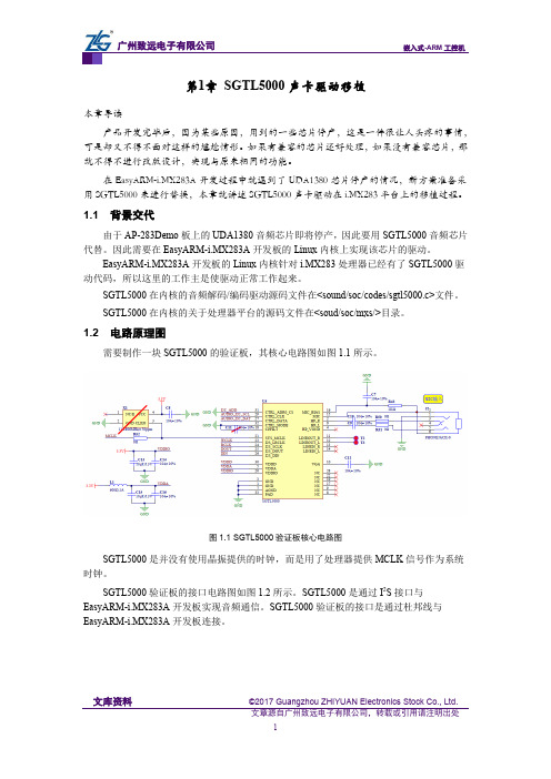
1.2 电路原理图需要制作一块SGTL5000的验证板,其核心电路图如图1.1所示。
图1.1 SGTL5000验证板核心电路图SGTL5000是并没有使用晶振提供的时钟,而是用了处理器提供MCLK 信号作为系统时钟。
SGTL5000验证板的接口电路图如图1.2所示。
SGTL5000是通过I 2S 接口与EasyARM-i.MX283A 开发板实现音频通信。
SGTL5000验证板的接口是通过杜邦线与EasyARM-i.MX283A 开发板连接。
文库资料 ©2017 Guangzhou ZHIYUAN Electronics Stock Co., Ltd.图1.2 SGTL5000验证板接口电路图SGTL5000验证板接口与 EasyARM-i.MX283A 开发板的连接方法如表1.1所示。
实验一_熟悉CCS5000开发工具(DSP开发环境基本操作)

实验一熟悉CCS5000开发工具(DSP开发环境基本操作)一实验目的(1)了解SEED-DTK5416开发板的构造及基本使用(2)了解CCS 2.0软件的配置方法(3)了解CCS软件的基本操作(4)掌握CCS软件的基本调试方法二实验内容1.CCS 2.0的配置2.DSP源文件的建立3.DSP程序工程文件的建立4.学习使用CCS集成开发工具的调试工具三实验原理1、SEED-DTK5416原理框图图1-1图1-1为SEED-DTK5416的功能框图(主要包括DSP、电源、仿真器、存储器、音频CODEC和扩展接口), 板上DSP支持其他54xx系列的芯片,如5409/5410/5416等,电源部分提供了板上所需的各种电源;板上64K-16bit的静态存储器(SRAM)在DSP以160MHz 速度运行时只需1个等待周期;128K-8bit Flash ROM映射为数据空间,用于启动时程序的自动装载(Boot Loading);TLV320AIC23B是TI推出的一款高性能的立体声音频Codec芯片,内置耳机输出放大器,支持MIC和LINE IN两种输入方式(二选一),且对输入和输出都有可编程增益调节。
扩展接口MCBSP可以对SEED-DTK5416的功能进行扩展。
SEED-DTK5416的工作状态:1.工作模式:微计算机模式2.BOOT模式:采用FLASH引导3.串口通讯:采用的A通道异步串行接口,RS232全双工方式4.音频输出:立体声输出左、右声道耳机驱动输出;2、SEED-DTK5416性能指标①高性能DSP:TMS320VC5416,主频160MHZ.②SDRAM:64K*16位(扩展至512K*16位)。
③Flash:256K*16位(扩展至1 M*16位)。
④提供看门狗电路、电源监视、上电复位、手动复位⑤2路编程可选的RS232/RS422/RS485⑥AC97标准的Audio音频接口⑦三路扩展串行接口⑧电源:单一电源供电(+5V),使用外接DC适配器提供电源。
飞思卡尔SGTL5000

Document Number: SGTL5000Rev. 3.0, 7/2010Freescale Semiconductor Advance Information* This document contains certain information on a new product.Specifications and information herein are subject to change without notice.© Freescale Semiconductor, Inc., 2008-2010. All rights reserved.Low Power Stereo Codec with Headphone AmpThe SGTL5000 is a Low Power Stereo Codec with Headphone Amp from Freescale, and is designed to provide a complete audio solution for portable products needing line-in, mic-in, line-out, headphone-out, and digital I/O. Deriving it’s architecture from best in class, Freescale integrated products that are currently on the market. The SGTL5000 is able to achieve ultra low power with very high performance and functionality, all in one of the smallest footprints available. Target markets include portable media players, GPS units, and smart phones. Features such as capless headphone design and an internal PLL, help lower overall system cost.FeaturesAnalog Inputs •Stereo Line In - Support for external analog input•Stereo Line In - Codec bypass for low power•MIC bias provided (5.0 x 5.0 mm QFN, 3.0 x 3.0 mm QFN TA2)•Programmable MIC gain •ADC - 85 dB SNR (-60 dB input) and -73 dB THD+N (VDDA = 1.8 V)Analog Outputs •HP Output - Capless design•HP Output - 45 mW max into 16 ohm load @ 3.3 V•HP Output - 100 dB SNR (-60 dB input) and -80 dB THD+N (V DDA = 1.8 V, 16 ohm load, DAC to headphone)•Line Out - 100 dB SNR (-60 dB input) and -85 dB THD+N (V DDIO = 3.3 V)Digital I/O•I 2S port to allow routing to Application Processor Integrated Digital Processing •Freescale Surround, Freescale Bass, tone control/ parametric equalizer/graphic equalizer Clocking/Control •PLL allows input of an 8.0 MHz to 27 MHz system clock - Standard audio clocks are derived from PLL Power Supplies•Designed to operate from 1.62 to 3.6 voltsFigure 1. SGTL5000 Simplified Application DiagramAUDIO CODECSGTL5000ORDERING INFORMATION Device TemperatureRange (T A )Package SGTL5000XNLA3/R2-40°C to 85°C20 QFNSGTL5000XNAA3/R232 QFNNote: Only I 2C is supported in the 3.0 mm x 3.0 mm 20-pin QFN package option.INTERNAL BLOCK DIAGRAMINTERNAL BLOCK DIAGRAMFigure 2. SGTL5000 Simplified Internal Block DiagramSGTL500Analog Integrated Circuit Device DataAnalog Integrated Circuit Device Data SGTL5000PIN CONNECTIONSPIN CONNECTIONSFigure 3. SGTL5000 Pin ConnectionsTable 1. SGTL5000 Pin DefinitionsA functional description can be found in Functional Description , beginning on page 12.20 Pin QFN 32 Pin QFNPin Name Pin Function Formal Name Definition12HP_R Analog Right headphone output23HP_VGND Analog Headphone virtual groundUse the widest, shortest trace possible for theHP_VGND35VDDA Power Analog voltage 46HP_L Analog Left headphone output-7AGND Analog Ground Ground-8, 9, 17, 19, 22, 28NC No Connect 510VAG Analog DAC VAG filter 611LINEOUT_R Analog Right line out 712LINEOUT_L Analog Left line out 813LINEIN_R Analog Right line in 914LINEIN_L Analog Left line in 1015MICAnalogMicrophone input 20 QFNTransparent Top View 32 QFNTransparent Top ViewHP_R HP_VGNDVDDA HP_L VAGL I N E O U T _RL I N E O U T _LL I N E I N _RL I N E I N _LM I CCPFLTVDDIO SYS_MCLK I2S_LRCLK I2S_SCLK I 2S _D O U TI 2S _D I NC T R L _D A T AC T R L _C L KV D D DL I N E O U T _RL I N E O U T _LL I N E I N _RL I N E I N _LM I CM I C _B I A SCPFLT NC I2S_LRCLK I2S_SCLK I 2S _D O U T I 2S _D I N C T R L _D A T AC T R L _C L KV D D DHP_R HP_VGNDVDDA HP_LNCGNDAGND NC NC C T R L _M O D EC T R I L _AD R 0_C SGND SYS_MCLK VDDIO V A GN CN CAnalog Integrated Circuit Device DataSGTL500PIN CONNECTIONS-16MIC_BIAS Analog Mic bias 1118CPFILT Analog Charge Pump Filter 1220VDDIO Power Digital I/O voltage 1321SYS_MCLK Digital System master clock 1423I2S_LRCLK Digital I 2S frame clock 1524I2S_SCLK Digital I 2S bit clock 1625I2S_DOUT Digital I 2S data output 1726I2S_DIN Digital I 2S data input 1827CTRL_DATADigitalI 2C Mode: Serial Data (SDA); SPI Mode: Serial Data Input (MOSI)1929CTRL_CLK DigitalI 2C Mode: Serial Clock (SCL); SPI Mode: Serial Clock (SCK)2030VDDD Digital Digital voltage -31CTRL_AD0_CSDigitalI 2C Mode: I 2C Address Select 0; SPI Mode: SPI Chip Select-32CTRL_MODE DigitalMode select for I 2C or SPI; When pulled low the control mode is I 2C, when pulled high the control mode is SPIPAD1, 4, PADGNDGroundGroundThe PAD should be soldered to ground. This is a suggestion for mechanical stability but is not required electrically.Star the ground pins of the chip, VAG ground, and all analog inputs/outputs to a single point, then to the ground plane.Table 1. SGTL5000 Pin Definitions (continued)A functional description can be found in Functional Description , beginning on page 12.20 Pin QFN 32 Pin QFNPin Name Pin Function Formal Name DefinitionAnalog Integrated Circuit Device Data SGTL5000ELECTRICAL CHARACTERISTICSMAXIMUM RATINGSELECTRICAL CHARACTERISTICSMAXIMUM RATINGSTable 2. Maximum RatingsExceeding the absolute maximum ratings shown in the following table could cause permanent damage to the part and is not recommended. Normal operation is not guaranteed at the absolute maximum ratings and extended exposure could affect long term reliability.RatingsSymbolValueUnitELECTRICAL RATINGS Maximum Digital Voltage V DDD 1.98V Maximum Digital I/O Voltage V DDIO 3.6V Maximum Analog Supply Voltage V DDA3.6V Maximum voltage on any digital input GND-0.3 to V DDIO +0.3V Maximum voltage on any analog input GND-0.3 to V DDA +0.3VRECOMMENDED OPERATING CONDITIONS Digital Voltage (If supplied externally)V DDD 1.1 to 2.0V Digital I/O Voltage V DDIO 1.62 to 3.6V Analog Supply Voltage V DDA1.62 to 3.6VTHERMAL RATINGS Storage Temperature T STG- 55 to 125°C Operating Temperature AmbientT A- 40 to 85°CAnalog Integrated Circuit Device DataSGTL500ELECTRICAL CHARACTERISTICSSTATIC ELECTRICAL CHARACTERISTICSSTATIC ELECTRICAL CHARACTERISTICSTable 3. Audio Performance 1Test Conditions unless otherwise noted: V DDIO = 1.8 V, V DDA = 1.8 V, T A = 25°C, Slave mode, f S = 48 kHz, MCLK = 256 f S , 24 bit input.CharacteristicSymbolMinTypMaxUnitAUDIO PERFORMANCE Line In Input Level -0.75-V RMS Line In Input Impedance 10--kOhmLINE IN -> ADC -> I 2S OUT SNR (-60 dB input)-85-dB THD+N--70-dB Frequency Response -±0.11-dB Channel Separation-79-dBLINE IN -> HEADPHONE_LINEOUT (CODEC BYPASS MODE)SNR (-60 dB input)-98-dB THD+N (10 kOhm load)--87-dB THD+N (16 Ohm load)--87-dB Frequency Response -±0.05-dB Channel Separation (1.0 kHz)82dBI 2S IN -> DAC -> LINE OUT Output Level -0.6-V RMS SNR (-60 dB input)-95-dB THD+N--85-dB Frequency Response-±0.12-dBI 2S IN -> DAC -> HEADPHONE OUT - 16 OHM LOAD Output Power -17-mW SNR (-60 dB input)-100-dB THD+N--80-dB Frequency Response-±0.12-dBI 2S IN -> DAC -> HEADPHONE OUT - 32 OHM LOAD Output Power -10-mW SNR (-60 dB input)-95-dB THD+N--86-dB Frequency Response-±0.11-dBI 2S IN -> DAC -> HEADPHONE OUT - 10 KOHM LOAD SNR (-60 dB input)-96-dB THD+N--84-dB Frequency Response-±0.11-dB PSRR (200 mVp-p @ 1.0 kHz on VDDA)-85-dBAnalog Integrated Circuit Device Data SGTL5000ELECTRICAL CHARACTERISTICSSTATIC ELECTRICAL CHARACTERISTICSTable 4. Audio Performance 2Test Conditions unless otherwise noted: V DDIO = 1.8 V, V DDA = 1.8 V, T A = 25°C, Slave mode, f S = 48 kHz, MCLK = 256 f S , 24 bit input. ADC tests were conducted with refbias = -37.5%, all other tests conducted with refbias = -50%.CharacteristicSymbolMinTypMaxUnitAUDIO PERFORMANCE Line In Input Level - 1.0-V RMS Line In Input Impedance 10--kOhmLINE IN -> ADC -> I 2S OUT SNR (-60 dB input)-90-dB THD+N--72-dB Frequency Response -±0.11-dB Channel Separation-80-dBLINE IN -> HEADPHONE_LINEOUT (CODEC BYPASS MODE)SNR (-60 dB input)-102-dB THD+N (10 kOhm load)--89-dB THD+N (16 Ohm load)--87-dB Frequency Response -±0.05-dB Channel Separation (1.0 kHz)81dBI 2S IN -> DAC -> LINE OUT Output Level - 1.0-V RMS SNR (-60 dB input)-100-dB THD+N--88-dB Frequency Response-±0.12-dBI 2S IN -> DAC -> HEADPHONE OUT - 16 OHM LOAD Output Power -58-mW SNR (-60 dB input)-98-dB THD+N--86-dB Frequency Response-±0.12-dBI 2S IN -> DAC -> HEADPHONE OUT - 32 OHM LOAD Output Power -30-mW SNR (-60 dB input)-100-dB THD+N--88-dB Frequency Response-±0.11-dBI 2S IN -> DAC -> HEADPHONE OUT - 10 KOHM LOAD SNR (-60 dB input)-97-dB THD+N--85-dB Frequency Response-±0.11-dB PSRR (200 mVp-p @ 1.0 kHz on VDDA)-89-dBAnalog Integrated Circuit Device DataSGTL500ELECTRICAL CHARACTERISTICSDYNAMIC ELECTRICAL CHARACTERISTICSDYNAMIC ELECTRICAL CHARACTERISTICSTable 5. Dynamic Electrical CharacteristicsCharacteristicSymbolMinTypMaxUnitPOWER UP TIMINGTime from all supplies powered up and SYS_MCLK present to initial communication. See Figure 4.t PC1.0(2)–-μsI2C BUS TIMING (3) See Figure 5.I 2C Serial Clock Frequency f I2C_CLK --400kHz I 2C Start condition hold time t I2CSH 150--ns I 2C Stop condition setup timet I2CSTSU 150--ns I 2C Data input setup time to rising edge of CTRL_CLKt I2CDSU 125--ns I 2C Data input hold time from falling edge of CTRL_CLK (receiving data)t I2CDH 5.0--ns I 2C Data input hold time from falling edge of CTRL_CLK (driving data)t I2CDH 360--ns I 2C CTRL_CLK low time t I2CCLKL 300--ns I 2C CTRL_CLK high time t I2CCLKH100--nsSPI BUS TIMING (4) See Figure 6.SPI Serial Clock Frequency f SPI_CLK --TBD MHz SPI data input setup time t SPIDSU 10--ns SPI data input hold time t SPIDH 10--ns SPI CTRL_CLK low time t SPICLKL TBD --ns SPI CTRL_CLK high time t SPICLKH TBD --ns SPI clock to chip select t CCS 60--ns SPI chip select to clock t CSC 20--ns SPI chip select low t CSL 20--ns SPI chip select hight CSH20nsSPECIFICATIONS AND TIMING FOR THE I 2S PORT (5) See Figure 7.Frequency of I 2S_LRCLK f LRCLK TBD --96kHz Frequency of I 2S_SCLK f SCLK -32*f LRCLK 64*f LRCLK-kHzI 2S delay t I2S_D --10ns I 2S setup time t I2S_S 10--ns I 2S hold timet I2S_H10--nsNotes1.The SGTL5000 has an internal reset that is deasserted 8 SYS_MCLK cycles after all power rails have been brought up. After this time,communication can start.2. 1.0μs represents 8 SYS_MCLK cycles at the minimum 8.0 MHz SYS_MCLK.3.This section provides timing for the SGTL5000 while in I 2C mode (CTRL_MODE = 0).4.This section provides timing for the SGTL5000 while in SPI mode (CTRL_MODE = 1)5.The following are the specifications and timing for I 2S port. The timing applies to all formats.Analog Integrated Circuit Device Data SGTL5000ELECTRICAL CHARACTERISTICSTIMING DIAGRAMSTIMING DIAGRAMSFigure 4. Power Up TimingFigure 5. I 2C Timing (CTRL_MODE == 0)Figure 6. SPI TimingAnalog Integrated Circuit Device DataSGTL500ELECTRICAL CHARACTERISTICS TIMING DIAGRAMS.Figure 7. I 2S Interface TimingFUNCTIONAL DESCRIPTIONINTRODUCTION FUNCTIONAL DESCRIPTIONINTRODUCTIONThe SGTL5000 is a low power stereo codec with integrated headphone amplifier. It is designed to provide a complete audio solution for portable products needing line-in, mic-in, line-out, headphone-out, and digital I/O. Deriving it’s architecture from best in class Freescale integrated products that are currently on the market, the SGTL5000 is able to achieve ultra low power with very high performance and functionality, all in one of the smallest footprints available. Target markets include portable media players, GPS units and smart phones. Features such as capless headphone design and USB clocking mode (12 MHz SYS_MCLK input) help lower overall system cost.In summary, the SGTL5000 accepts the following inputs:•Line input•Microphone input, with mic bias (mic bias only available in 32QFN version)•Digital I2S inputIn addition, the SGTL5000 supports the following outputs:•Line output•Headphone output•Digital I2S outputThe following digital audio processing is included to allow for product differentiation:•Digital mixer•Freescale Surround•Freescale Bass Enhancement•Tone Control, parametric equalizer, and graphic equalizer The SGTL5000 can accept an external standard master clock at a multiple of the sampling frequency (i.e. 256*Fs, 385*Fs, 512*Fs). In addition it can take non standard frequencies and use the internal PLL to derive the audio clocks. The device supports 8.0 kHz, 11.025 kHz, 16 kHz, 22.5 kHz, 24 kHz, 32 kHz, 44.1kHz, 48 kHz, 96 kHz sampling frequencies.FUNCTIONAL INTERNAL BLOCK DESCRIPTIONSYSTEM BLOCK DIAGRAM W/ SIGNAL FLOW AND GAIN MAPFigure 8 shows a block diagram that highlights the signal flow and gain map for the SGTL5000.To guarantee against clipping it is important that the gain in a signal path in addition to the signal level does not exceed 0 dB at any point.Figure 8. System Block Diagram, Signal Flow and GainFUNCTIONAL DESCRIPTIONFUNCTIONAL INTERNAL BLOCK DESCRIPTIONPOWERThe SGTL5000 has a flexible power architecture to allow the system designer to minimize power consumption and maximize performance at the lowest cost.External Power SuppliesThe SGTL5000 requires 2 external power supplies: VDDA and VDDIO. An optional third external power supply VDDD may be provided externally to achieve lower power. A description for the different power supplies is as follows:•VDDA: This external power supply is used for the internal analog circuitry including ADC, DAC, LINE inputs, MIC inputs, headphone outputs and reference voltages. VDDA supply ranges are shown in Maximum Ratings. Adecoupling cap should be used on VDDA, as shown in the typical application diagrams in Typical Applications.•VDDIO: This external power supply controls the digital I/O levels as well as the output level of LINE outputs. VDDIO supply ranges are shown in Maximum Ratings. Adecoupling cap should be used on VDDIO as shown in the typical application diagrams in Typical Applications.Note that if VDDA and VDDIO are derived from the same voltage, a single decoupling capacitor can be used to minimize cost. This capacitor should be placed closest to VDDA.•VDDD: This is a digital power supply that is used for internal digital circuitry. For a low cost design, this supply can be derived from an internal regulator and no external components are required. If no external supply is applied to VDDD, the internal regulator will automatically be used.For lowest power, this supply can be driven at the lowest specified voltage given in Maximum Ratings. If an external supply is used for VDDD, a decoupling capacitor isrecommended. VDDD supply ranges are shown inMaximum Ratings, for when externally driven. If thesystem drives VDDD externally, an efficient switchingsupply should be used or no system power savings will be realized.Internal Power SuppliesThe SGTL5000 has two exposed internal power supplies, VAG and charge pump.•VAG is the internal voltage reference for the ADC and DAC. After startup the voltage of VAG should be set to VDDA/2 by writing CHIP_REF_CTRL->VAG_VAL. Refer to programming Chip Powerup and Supply Configurations.The VAG pin should have an external filter capacitor as shown in the typical application diagram.•Chargepump: This power supply is used for internal analog switches. If VDDA or VDDIO is greater than 2.7 V, this supply is automatically driven from the highest ofVDDIO and VDDA. If both VDDIO and VDDA are less than3.1 V, then the user should turn on the charge pumpfunction to create the chargepump rail from VDDIO by writing CHIP_ANA_POWER->VDDC_CHRGPMP_POWERUP register. Refer toprogramming Chip Powerup and Supply Configurations.•LINE_OUT_VAG is the line output voltage reference. It should be set to VDDIO/2 by writingCHIP_LINE_OUT_CTRL->LO_VAGCNTRL.Power SchemesThe SGTL5000 supports a flexible architecture and allows the system designer to minimize power or maximize BOM savings.•For maximum cost savings, all supplies can be run at the same voltage.•Alternatively for minimum power, the analog and digital supplies can be run at minimum voltage while driving the digital I/O voltage at the voltage needed by the system.•To save power, independent supplies are provided for line outputs and headphone outputs. This allows for 1VRMS line outputs while using minimal headphone power.•For best power, VDDA should be run at the lowest possible voltage required for the maximum headphone output level. For highest performance, VDDA should be run at 3.3 V. For most applications a lower voltage can be used for the best performance/power combination. RESETThe SGTL5000 has an internal reset that is deasserted 8 SYS_MCLKs after all power rails have been brought up. After this time communication can start. See Dynamic Electrical Characteristics.CLOCKINGClocking for the SGTL5000 is provided by a system master clock input (SYS_MCLK). SYS_MCLK should be synchronous to the sampling rate (Fs) of the I2S port. Alternatively any clock between 8.0 and 27 Mhz can be provided on SYS_MCLK and the SGTL5000 can use an internal PLL to derive all internal and I2S clocks. This allows the system to use an available clock such as 12 MHz (common USB clock) for SYS_MCLK to reduce overall system costs.Synchronous SYS_MCLK inputThe SGTL5000 supports various combinations ofSYS_MCLK frequency and sampling frequency as shown in Table 6. Using a synchronous SYS_MCLK allows for lower power as the internal PLL is not used.FUNCTIONAL DESCRIPTION FUNCTIONAL INTERNAL BLOCK DESCRIPTIONUsing the PLL - Asynchronous SYS_MCLK input An integrated PLL is provided in the SGTL5000 that allows any clock from 8.0 to 27 MHz to be connected to SYS_MCLK. This can help save system costs, as a clock available elsewhere in the system can be used to derive all audio clocks using the internal PLL. In this case, the clock input to SYS_MCLK can be asynchronous with the sampling frequency needed in the system. For example, a 12 MHz clock from the system processor could be used as the clock input to the SGTL5000.Three register fields need to be configured to properly use the PLL. They are CHIP_PLL_CTRL->INT_DIVISOR, CHIP_PLL_CTRL->FRAC_DIVISOR andCHIP_CLK_TOP_CTRL->INPUT_FREQ_DIV2. Figure 9 shows a flowchart that shows how to determine the values to program in the register fields.Figure 9. PLL Programming FlowchartFor example, when a 12 MHz digital signal is placed on MCLK, for a 48 kHz frame clockCHIP_CLK_TOP_CTRL->INPUT_FREQ_DIV2 = 0 // SYS_MCLK < 17 MHzCHIP_PLL_CTRL->INT_DIVISOR = FLOOR(196.608 MHz/12 MHz) = 16 (decimal)CHIP_PLL_CTRL->FRAC_DIVISOR = ((196.608 MHz/ 12 MHz) - 16) * 2048 = 786 (decimal)Refer to PLL programming PLL Configuration.AUDIO SWITCH (SOURCE SELECT SWITCH)The audio switch is the central routing block that controls the signal flow from input to output. Any single input can be routed to any single or multiple outputs.Any signal can be routed to the Digital Audio Processor (DAP). The output of the DAP (an input to the audio switch) can in turn be routed to any physical output. The output of the DAP can not be routed into itself. Refer to Digital Audio Processing, for DAP information and configuration.It should be noted that the analog bypass from Line input to headphone output does not go through the audio switch.Table 6. Synchronous MCLK RatesCLOCK SUPPORTED RATES UNITS System Master Clock (SYS_MCLK)256, 384, 512Fs Sampling Frequency (Fs)8, 11.025, 16, 22.5, 32, 44.1, 48, 96 (6)kHzNotes6.For a sampling frequency of 96 kHz, only 256 Fs SYS_MCLK is supportedFUNCTIONAL DESCRIPTIONFUNCTIONAL INTERNAL BLOCK DESCRIPTIONTo configure a route, the CHIP_SSS_CTRL register is used. Each output from the source select switch has its own register field that is used to select what input is routed to that output.For example, to route the I2S digital input through the DAP and then out to the DAC (headphone) outputs writeSSS_CTRL->DAP_SELECT to 0x1 (selects I2S_IN) and SSS_CTRL->DAC_SELECT to 0x3 (selects DAP output). ANALOG INPUT BLOCKThe analog input block contains a stereo line input and a microphone input with mic bias (in the 32 QFN package). Either input can be routed to the ADC. The line input can also configured to bypass the CODEC and be routed the analog input directly to the headphone output.Line InputsOne stereo line input is provided for connection to line sources such as an FM radio or MP3 input.The source should be connected to the left and right line inputs through series coupling capacitors. The suggested value is shown in the typical application diagram in Typical Applications.As detailed in ADC, the line input can be routed to the ADC.The line input can also be routed to the headphone output by writing CHIP_ANA_CTRL->SELECT_HP. This selection bypasses the ADC and audio switch and routes the line input directly to the headphone output to enable a very low power pass through.Microphone InputOne mono microphone input is provided for uses such as voice recording.Mic bias is provided in the 32QFN package. The mic bias is can be programmed with the CHIP_MIC_CTRL->BIAS_VOLT register field. Values from 1.25 V to 3.00 V are supported in 0.25 V steps. Mic bias should be set less than 200 mV from VDDA, e.g. with VDDA at 1.70 V, Mic bias should be set no greater than 1.50 V.The microphone should be connected through a series coupling capacitor. The suggested value is shown in the typical connection diagram.The microphone has programmable gain through the CHIP_MIC_CTRL->GAIN register field. Values of 0 dB,+20 dB, +30 dB and +40 dB are available.ADCThe SGTL5000 contains an ADC who takes its input from either the line input or a microphone. The register field CHIP_ANA_CTRL->SELECT_ADC controls this selection. The output of the ADC feeds the audio switch.The ADC has its own analog gain stage that provides 0 to +22.5 dB of gain in 1.5 dB steps. A bit is available that shifts this range down by 6.0 dB to effectively provide -6.0 dB to +16.5 dB of gain. The ADC gain is controlled in theCHIP_ANA_ADC_CTRL register.The ADC has an available zero cross detect (ZCD) that will prevent any volume change until a zero-volt crossing of the audio signal is detected. This helps in eliminating pop or other audio anomalies. If the ADC is to be used, the chip reference bias current should not be set to -50% when in 3.0 V mode. ANALOG OUTPUTSThe SGTL5000 contains a single stereo DAC that can be used to drive a headphone output and a line output. The DAC receives its input from the audio switch. The headphone output and the line output can be driven at the same time from the DAC.The headphone output can also be driven directly by the line input bypassing the ADC and DAC for a very low power mode of operation.The headphone output is powered by VDDA while the line output is powered by VDDIO. This allows the headphone output to be run at the lowest possible voltage while the line output can still meet line output level requirements.DACThe DAC output is routed to the headphone and the dedicated line output.The DAC output has a digital volume control from -90 dB to 0 dB in ~0.5 dB step sizes. This volume is shared among headphone output and line output. The registerCHIP_DAC_VOL controls the DAC volume.HeadphoneStereo headphone outputs are provided which can be used to drive a headphone load or a line level output. The headphone output has its own independent analog volume control with a volume range of -52 dB to +12 dB in 0.5 dB step sizes. This volume control can be used in addition to the DAC volume control. For best performance the DAC volume control should be left at 0 dB until the headphone is brought to its lowest setting of -52 dB. The registerCHIP_ANA_HP_CTRL is used to control the headphone volume.The headphone output has an independent mute that is controlled by the register field CHIP_ANA_CTRL->MUTE_HP.The line input is routed to the headphone output by writing CHIP_ANA_CTRL->SELECT_HP. This selection bypasses the ADC and audio switch and routes the line input directly to the headphone output to enable a very low power pass through. When the line input is routed to the headphone output, only the headphone analog volume and mute will affect the headphone output.The headphone has an available zero cross detect (ZCD) which, as previously described, will prevent any volume change until a zero-volt crossing of the audio signal is detected. This helps in eliminating pop or other audio anomalies.FUNCTIONAL DESCRIPTION FUNCTIONAL INTERNAL BLOCK DESCRIPTIONLine OutputsThe SGTL5000 contains a stereo line output. The line output has a dedicated gain stage that can be used to adjust the output level. The CHIP_LINE_OUT_VOL controls the line level output gain.The line outputs also have a dedicated mute that is controlled by the register field CHIP_ANA_CTRL->MUTE_LO.The line out volume is intended as maximum output level adjustment. It is intended to be used to set the maximum output swing. It does not have the range of a typical volume control and does not have a zero cross detect (ZCD). However the dac digital volume could be used if volume control is desired.FUNCTIONAL DEVICE OPERATIONFUNCTIONAL INTERNAL BLOCK DESCRIPTIONFUNCTIONAL DEVICE OPERATION POWER CONSUMPTIONV DDD derived internally @ 1.2 V, slave mode except for PLL case, 32 ohm load on HP, Conditions: -100 dBFs signal input, slave mode unless otherwise noted, paths tested as indicated, unused paths turned off.A further 0.5-1.0 mW reduction in power is expected with TA2 silicon.DIGITAL INPUT & OUTPUTOne I2S (Digital Audio) Port is provided which supports the following formats: I2S, Left Justified, Right Justified, and PCM mode.I2S, Left Justified, and Right Justified Modes I2S, Left Justified and Right Justified modes are stereo interface formats. The I2S_SCLK frequency, I2S_SCLK polarity, I2S_DIN/DOUT data length, and I2S_LRCLK polarity can all be change through the CHIP_I2S_CTRLTable 7. Power Consumption: V DDA=1.8 V, V DDIO=1.8 VMODECURRENT CONSUMPTION (MA)POWER (MW) V DDD V DDA V DDIOPlayback (I2S->DAC->Headphone)- 2.540.9 6.19 Playback with DAP ((I2S->DAP->DAC->Headphone)- 3.590.98.08 Playback/Record (I2S->DAC->Headphone, ADC->I2S)- 3.71 1.108.67 Record (ADC->I2S)- 2.29 1.06 6.02 Analog playback, CODEC bypassed (LINEIN->HP)- 1.480.89 4.27 Standby, all analog power off-0.0190.0020.038 Playback with PLL (I2S->DAC->HP)- 3.01 2.179.31Table 8. Power Consumption: V DDA=3.3 V, V DDIO=3.3 VMODECURRENT CONSUMPTION (MA)POWER(MW) V DDD V DDA V DDIOPlayback (I2S->DAC->Headphone)- 3.450.06711.60 Playback with DAP ((I2S->DAP->DAC->Headphone)- 4.490.06715.03 Playback/Record (I2S->DAC->Headphone, ADC->I2S)- 4.670.34316.53 Record (ADC->I2S)- 2.900.29610.56 Analog playback, CODEC bypassed (LINEIN->HP)- 1.910.039 6.43 Standby, all analog power off-0.040.0020.139 Playback with PLL (I2S->DAC->HP)- 3.92 2.7622.05。
- 1、下载文档前请自行甄别文档内容的完整性,平台不提供额外的编辑、内容补充、找答案等附加服务。
- 2、"仅部分预览"的文档,不可在线预览部分如存在完整性等问题,可反馈申请退款(可完整预览的文档不适用该条件!)。
- 3、如文档侵犯您的权益,请联系客服反馈,我们会尽快为您处理(人工客服工作时间:9:00-18:30)。
Freescale SemiconductorApplication Note1DescriptionSGTL5000 supports multiple forms of I2S communication for digital input/output. Along with the more typical Left- or Right-justified configuration, SGTL5000 includes support for a mode aimed at signals as seen in digital signal processing (DSP) applications, e.g. Bluetooth transceivers. This document will help explain the usage and configuration of SGTL5000’s I2S DSP mode.2 DSP ModeThe purpose of the I2S DSP Mode (A/B) is to interface with various external devices, such as Bluetooth transceivers. Where it differs from standard I2S is that the frame clock does not represent a different channel when high or low, but is a bit-wide pulse that marks the start of a frame. Data is aligned such that the left channel data is immediately followed by right channel data. Zero padding is filled in for the remaining bits. The data and frame clock may be configured to clock in on the rising or falling edge of Bit Clock.Document Number:AN3664Rev. 2, 11/2011Contents1.Description . . . . . . . . . . . . . . . . . . . . . . . . . . . . . . . . . 12.DSP Mode . . . . . . . . . . . . . . . . . . . . . . . . . . . . . . . . . . 13.Conclusion . . . . . . . . . . . . . . . . . . . . . . . . . . . . . . . . . 5SGTL5000 I2S DSP ModeDSP ModeSGTL5000 supports LRCLK frequencies of as low as 8kHz, for Bluetooth-type applications by accepting an input clock, and dividing down to the necessary LRCLK.To specify the proper rate, the following should be written to RATE_MODE (bits 5:4) inCHIP_CLK_CTRL:0x0 = SYS_FS specifies the rate0x1 = Rate is 1/2 of the SYS_FS rate0x2 = Rate is 1/4 of the SYS_FS rate0x3 = Rate is 1/6 of the SYS_FS ratee.g. to get an 8kHz Bluetooth sample rate from an incoming 48kHz clock, 0x3 must be written to RATE_MODE.The following are functional diagrams of DSP mode with 32 and 64 SCLKFREQ, respectively:To enable DSP Mode in SGTL5000, write 0x2 to I2S_MODE (bits 3:2) in CHIP_I2S0_CTRL. Data alignment is crucial. Both the sender and receiver of data must be set up identically to properly transmit information. For example, in order to transmit to an Audio Precision 2700, the data must be aligned on the falling edge of I2S_SCLK, therefore, SCLK_INV (bit 6:6) in CHIP_I2S0_CTRL must be set.DSP Mode Figure1, Figure2 and Figure3, following, show oscilloscope outputs of DSP Mode.Figure1. Here, showing a 32-bit frame, with left- and right-channel data being transmittedDSP ModeFigure2. SGTL5000 also supports 32-bit-per-channel data, using a 64-SCLK frameConclusionFigure3. Close-up of data alignment in reference to the LR bit-pulse (Ch 3)3ConclusionSGTL5000 offers compatibility with many different digital I/O schemes in order to provide support to as many applications as possible. Understanding the use of DSP mode will ensure proper communication between a Bluetooth-type device and SGTL5000.4.0RevisionHistoryHow to Reach Us:Home Page:Web Support:/supportUSA/Europe or Locations Not Listed:Freescale Semiconductor, Inc.Technical Information Center, EL5162100 East Elliot Road Tempe, Arizona 852841-800-521-6274 or +/supportEurope, Middle East, and Africa:Freescale Halbleiter Deutschland GmbH Technical Information Center Schatzbogen 781829 Muenchen, Germany +44 1296 380 456 (English)+46 8 52200080 (English)+49 89 92103 559 (German)+33 1 69 35 48 48 (French)/supportJapan:Freescale Semiconductor Japan Ltd.Headquarters ARCO Tower 15F 1-8-1, Shimo-Meguro, Meguro-ku,Tokyo 153-0064Japan 0120 191014 or +81 3 5437 9125support.japan@Asia/Pacific:Freescale Semiconductor China Ltd.Exchange Building 23F No. 118 Jianguo Road Chaoyang District Beijing 100022China +86 10 5879 @For Literature Requests Only:Freescale Semiconductor Literature Distribution Center P .O. Box 5405Denver, Colorado 802171-800-441-2447 or +1-303-675-2140Fax: +1-303-675-2150LDCForFreescaleSemiconductor@ Freescale and the Freescale logo are trademarks of Freescale Semiconductor, Inc., Reg. U.S. Pat. & Tm. Off. Qorivva, S12 MagniV, SMARTMOS and Xtrinsic are trademarks of FreescaleSemiconductor, Inc. ARM is the registered trademark of ARMLimited. The Power Architecture and word marks and the Power and logos and related marks are trademarks and service marks licensed by . All other product or service names are the property of their respective owners. ©2011 Freescale Semiconductor, Inc.AN3664Rev. 2.0Information in this document is provided solely to enable system and software implementers to use Freescale Semiconductor products. There are no express or implied copyright licenses granted hereunder to design or fabricate any integrated circuits or integrated circuits based on the information in this document.Freescale Semiconductor reserves the right to make changes without further to products herein. Freescale Semiconductor makes no warranty, representation or regarding the suitability of its products for any particular purpose, nor does Freescale Semiconductor assume any liability arising out of the or use of any product or circuit, and specifically disclaims any and all liability, including without limitation consequential or incidental damages. “Typical” parameters that may be provided in Freescale Semiconductor data sheets and/or specifications can and do vary in different applications and actual performance may vary over time. All operating parameters, including “Typicals”, be validated for each customer application by technical experts. Freescale Semiconductor does not convey any license under its patent rights nor the rights of others. Freescale Semiconductor products are designed, intended, or authorized for use as components in systems intended for surgical implant into the body, or other applications intended to support or sustain life, or for any other application in which the failure of the Freescale Semiconductor product could create a situation where personal injury or death may occur. Should Buyer purchase or use Freescale Semiconductor products for any such unintended or unauthorized application, Buyer shall indemnify and hold Freescale Semiconductor and its officers, employees, subsidiaries, affiliates, and harmless against all claims, costs, damages, andexpenses, and reasonable attorney fees arising out of, directly or indirectly, any claim of personal injury or death associated with such unintended or unauthorized use, even if such claim alleges that Freescale Semiconductor was negligent regarding the design or manufacture of the part.。