F1赛车悬挂系统之FRIC
f1方程式赛车的基础知识
f1方程式赛车的基础知识F1方程式赛车是一项世界知名的汽车竞技项目,也被称为“汽车界的皇冠”,它具有激烈的竞争、高速的赛车以及先进的技术。
F1方程式赛车运动起源于20世纪初的欧洲,经过一百多年的发展与演变,如今已成为世界范围内最受欢迎的赛车运动之一。
一、赛车技术1.1 发动机:F1赛车的发动机是其最重要的部分之一。
通常采用V 型8缸引擎,最大转速可达18000转/分钟,功率超过900马力。
这种高性能的发动机使得F1赛车能够在短时间内达到极高的速度,并在赛道上展现出卓越的加速性能。
1.2 底盘:F1赛车的底盘采用碳纤维复合材料制造,重量轻、强度高,能够在高速行驶时提供足够的稳定性和刚性,同时也能够有效减少风阻。
1.3 悬挂系统:F1赛车的悬挂系统采用独立悬挂设计,使得车辆在高速行驶时能够更好地吸收震动,保持稳定性和操控性。
1.4 制动系统:F1赛车的制动系统采用碳碳盘制动器,这种制动器具有更高的耐高温性能和制动力,能够在高速行驶时提供更好的刹车效果。
1.5 风洞测试:F1赛车的设计和优化是通过风洞测试来完成的。
在风洞中,工程师们可以模拟不同速度和角度下的空气流动情况,通过对赛车外形和空气动力学性能的调整,提高赛车的速度和稳定性。
二、赛车规则2.1 赛道:F1赛车的赛道一般是固定的,包括直线、弯道和复杂的S弯等。
赛道的长度一般在4-7公里之间,不同赛道的特点也不尽相同,例如蒙特卡洛赛道的弯道多、摩纳哥赛道的狭窄等。
2.2 赛制:F1赛车的比赛一般分为正赛和排位赛两个阶段。
排位赛用于决定赛车的起跑顺序,正赛则根据起跑顺序进行比赛,并在规定的圈数内确定最终名次。
2.3 技术规则:F1赛车的技术规则非常严格,包括发动机的规格、车身重量、燃料消耗等方面的要求,旨在确保比赛的公平性和安全性。
2.4 裁判判罚:F1赛车的比赛中有专门的裁判团队负责监督比赛的进行,并对违反规则的车辆进行判罚,例如罚时、罚款和取消成绩等。
F-SAE赛车后悬架优化分析

图 5 主 销 内倾 角 变 化 曲线
图 2 车 轮 外 倾 角变 化 曲线
3 模 型 的优 化 分 析
A AMS 为用户提 供 了强大 的参数化 分析功 D
J’— _ ● — 啪_ _¨ l
i
能 ,参数化 分析 有利于 了解各 设计变 量对样 机性
、
\
\ \
能 的影响 ,在参数 化分 析过程 中 ,根 据参数 化建 模 时建立 的设计变 量 ,采 用不 同的参 数值 ,进 行
轮胎 的磨损量 ,说 明该悬 架结 构参 数还存 在 不合
(1减振器简化为线性弹簧和阻尼 ; 2
()各 运动 副 内的摩擦 力 忽 略不计 ; 3
作 者简 介 :郭 ̄ (9 5) 男,硕 士研 究生 ,研 究方 向 :汽车 安全 设计 。 18~,
理 的地方 ,有 待 进一 步 改进 。
一
\
、
、 、 、
舢 舢 ¨ 0 j 1 D ”
系 列的仿 真 。然 后根据 返回 的分析 结果进行 参
数化 分析 ,再进 一步对各 参数 进行优 化分析 。本
文根 据分析 的需要 ,确 定相关 的关键 变量 ,并将
ml 2 附些 关键变 量设置 为可 以改变 的设计 变量 。在 分 析 时,只需 改变这些 设计 变量 的大小 ,虚拟样 机 模型 即可 自动更新 。
F AE 车 运 动 中后 悬 架 随车 轮 上 下跳 动 时 定位 参 数 的变 化规 律 , 评 价 悬 架 数据 合 理 性 。 采 用 优 化 分 析 对 悬 架 不 合 理 数 S 赛 据 进 行 优 化 ,进 一 步 改 善 悬 架 系 统 性 能 , 以提 高 产 品 开发 质 量 。 关 键 词 :赛 车 独 立 悬 架 ;A M S 优 化 分 析 DA ;
F1的功能介绍范文
F1的功能介绍范文F1,全称为Formula One,是世界上最高级别的汽车赛事之一、作为赛车运动的顶级赛事,F1拥有许多令人惊叹的功能和技术。
本文将介绍F1的一些重要功能,并详细解释它们在赛车领域的作用。
首先,F1赛车的动力系统是其最关键的功能之一、这些赛车搭载有高性能的内燃机,通常采用V6涡轮增压引擎。
这些引擎具有出色的马力和扭矩,使F1赛车能够以极高速度行驶。
此外,F1赛车还具备可调节的后翼板和前翼板,以及在赛车后部产生下压力的地效器,这些功能提供了额外的空气动力学支持,以提高赛车的稳定性和操控性能。
其次,F1赛车采用了最先进的底盘和悬挂系统。
赛车的底盘通常由轻量化的碳纤维复合材料构成,以提供出色的刚性和轻量化。
同时,F1赛车的悬挂系统使用被称为“活塞式悬挂”的先进技术,以最大程度地减少悬挂部件的质量,并提供更好的悬挂调节性能,以适应不同的赛道条件。
第三,F1赛车还配置了先进的刹车系统。
赛车的刹车系统采用了碳陶瓷刹车片和刹车盘,具有更高的刹车能力和稳定性。
此外,赛车的刹车系统还配备了动力回收系统,将刹车时产生的能量转换为电能,并储存在赛车上的电池中,这样可以在需要的时候提供额外的动力。
第四,F1赛车的变速器系统也非常先进。
赛车通常采用半自动的无级变速器,这种变速器可以在不间断加速的情况下实现快速、平稳的换档操作。
此外,变速器还配备了电子控制单元(ECU),用于管理引擎和变速器的运行,并对赛车的性能进行调整。
第五,F1赛车的轮胎也是非常特殊的。
赛车使用的轮胎采用软胶材料制成,以提供更好的抓地力和操控性能。
赛车的都市部分还具备速度可调节高级模式和Start催化系统。
第六,F1赛车还具备先进的数据采集和传输系统。
这些系统能够收集大量的数据,如赛车的速度、加速度、刹车压力、转速、温度等等,并将这些数据实时传输到赛车队的指挥中心。
通过分析这些数据,工程师们可以更好地了解赛车的性能和状态,并据此作出相应的调整和决策。
class-f-1原理 -回复

class-f-1原理-回复Class F1原理是一种机械工程中的原理,它可以被用来设计和开发高性能的赛车。
在这篇文章中,我将详细解释Class F1原理的各个方面,并回答一些与此相关的问题。
什么是Class F1原理?Class F1原理是一种应用于赛车设计和开发的原理,用于确保赛车的高性能和安全性。
这个原理是根据国际汽车联合会(FIA)赛车技术规则制定的,该组织是负责管理和监督全球各种汽车比赛的国际机构。
Class F1原理主要关注以下几个方面:1. 安全性:这是Class F1原理的首要目标。
赛车必须具备一系列的安全设备,如安全座椅、头盔、防火服等,并且必须符合FIA规定的安全标准。
2. 性能:Class F1原理要求赛车在性能方面尽可能达到极限。
赛车必须具备高速、高加速和高刹车能力,并且要具备稳定的操控性能。
3. 可靠性:赛车必须具备足够的可靠性,以确保在极端条件下的长时间运行。
在比赛过程中,所有的部件和系统必须经受住各种考验,如高温、高压和高振动等。
4. 环保性:赛车必须符合FIA关于环保的规定,如排放标准和噪音限制等。
尽管赛车使用高性能发动机和燃料,但还是必须尽可能减少对环境的不良影响。
Class F1原理的具体要求包括:1. 赛车结构:赛车必须具备坚固的车身和底盘,以确保安全性和稳定性。
车身和底盘必须符合FIA规定的强度和刚度要求。
2. 发动机:赛车必须使用内燃机动力系统,并且发动机的排气量、压缩比和最大输出功率等参数必须符合FIA的规定。
3. 悬挂系统:赛车的悬挂系统必须能够提供足够的悬挂行程和良好的悬挂刚度,以保证赛车在高速行驶和高加速情况下的稳定性和操控性能。
4. 制动系统:赛车必须配置强大和可靠的制动系统,以确保在高速情况下的安全停车和制动效果。
5. 轮胎:赛车必须使用符合FIA规定的赛车专用轮胎,这些轮胎具有良好的抓地力和操控性能,以适应赛道上的各种路况。
通过遵循Class F1原理,赛车制造商可以设计和开发出高性能、安全可靠的赛车。
赛车零件个个的解析
赛车零件个个的解析
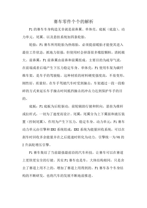
F1的赛车车身构造无非就是前鼻翼、单体壳、底板(底盘)、动力单元、尾翼、以及悬挂系统加四条轮胎。
轮胎:F1赛车所用轮胎为热熔胎,必须提前暖胎才能使其进入最佳工作状态,抓地力很强,但使用时会掉落很多橡胶颗粒,消耗极大。
前鼻翼:F1前鼻翼由前鼻和前翼组成。
主要目的为疏导气流,在前端或者后端产生下压力稳定车身。
单体壳:F1使用车架为碳纤维车架,是车手的驾驶舱。
这种材质的材料硬度强度高,不易变形,刚性好,质量轻。
在车手驾驶汽车时受到撞击,车架通过一段一段粉碎的方式来延长车手撞击时间抵挡撞击的冲击力达到保护车手的目的。
底板:F1底板为后轮驱动,前轮辅助行驶和转向,悬挂为推杆或拉杆式,一切为了速度而设计。
尾翼:尾翼分为上下翼面和液压装置(控制尾翼)。
作用为产生下压力,稳定车身。
动力单元:F1赛车动力单元由引擎和ERS系统组成,ERS系统为能量回收系统,可以在刹车时回收多余能量并在之后提速时转化为动力。
引擎统一为V6的2升涡轮增压引擎。
F1赛车集结了当前最强最前沿的汽车科技,让赛车可以在赛道上更快更安全的行驶。
其实F1赛车也是车,大体结构相同,只是舍去了赛道上用不上的,增加了赛道上用得到的。
F1赛车各个车身结构的不断研发,也将汽车的发展不断地前推进。
F1赛车前定风翼工作原理介绍

Front wing aerodynamicsBy Steven De Groote on 18 Jun 2003, 16:27The front wing of a Formula One car creates about 25% of the total cars downforce. Although this only occurs in ideal circumstances. When a preceding car runs less than 20m in front, the total downforce generated by the front wing may become as little as 30% of its normal downforce. Although this reduce of drag (because the air pressure is lower behind a car's rear wing), enables higher speeds at the end of straight, it significantly hinders the pursuing car in corners, as he cannot take these at normal speeds. This problem mostly occurs in fast corners, and is one of the most important reasons of the overtaking problem currently in Formula One. It is therefore a hard job to create a performing front wing, even more because disturbing the airflow too much will affect the rest of the car's aerodynamic efficiency too.Regulations3.4 Width ahead of the rear wheel centre line :3.4.1 Bodywork width ahead of the rear wheel centre line must not exceed1400mm.3.4.2 In order to prevent tyre damage to other cars, the top and forward edges of the lateral extremities of any bodywork forward of the front wheels must be at least 10mm thick with a radius of at least 5mm.3.7 Front bodywork height:All bodywork situated forward of a point lying 330mm behind the front wheel centre line, and more than 250mm from the centre line of the car, must be no less than 100mm and no more than 300mm above the reference plane.3.17.1 Bodywork may deflect no more than 5mm vertically when a 500N load is applied vertically to it 700mm forward of the front wheel centre line and 625mm from the car centre line. The load will be applied in a downward direction using a 50mm diameter ram and an adapter 300mm long and 150mm wide. Teams must supply the latter when such a test is deemed necessary.Front wing designA regular front aerofoil is made as a main plane running the whole width of the car (almost at least, limited by FIA regulations) suspended from the nose. Onto this are fitted one or more flaps which are the adjustable parts of the wing. On each end of the mainplane there are endplates. These make sure the airflow passes above and beneath the wing rather than around it. In recent years theseendplates have played a crucial role in influencing the airflow around the front tyres, especially after the rule changes at the beginning of 1998 (wheelbase made smaller from 220cm to 180cm). These changes made front wing airflow interfere with the rotating airflow around the front wheels.Article 3.17 has been introduced during 1998, after teams started experimenting with bending front and rear wings. When Ferrari introduced such a front wing at the end of 1997, it was produced in such a way that the wing would flex under aerodynamic loads. This means that as the speed increased, a force was produced that pushed the wing towards the ground. By means of a ground effect, this was particularly interesting for front wings because if would increase downforce at high speeds without an increase of drag. As rear wings began to fail and flew off during races, the FIA thought it was time to act and added 3.17 to the technical regulations of Formula One.At the beginning of 2001, front wing regulations had changed in such a way, that the wing should be 100mm above the ground at least, instead of the 40mm until then. The FIA introduced this change to limit the cornering speeds of the cars. The idea was to decrease the ground effect that was generated by front wings close to the ground, working just like a diffuser.Immediately at the start of the season, Ferrari introduced a front wing that was bent down in the center line or the car. This new concept makes a handy use of a little hole in the regulations. The whole is the result of a rule, added in 1994, where the wooden bottom made it's entry. This wooden plate can be hung up as low as possible to the ground. As this plate is 50 cm wide, it was not foreseen that the front wing may be placed that low to the ground in 25cm at each side of the center of the car. Since the introduction by Ferrari, more and more teams have adopted the idea of curved front wings, with them also McLaren and Renault (see picture).Though the reason that McLaren didn't make any of those changes until 2002, might have to do with the curve of the front wing before the change of regulations. It was namely curved up in the middle, so that the inner side washigher above the ground then both outer sides of the front wing. This type of wing is mostly useful on fast tracks where not much downforce is needed. It is there that airflow in the centre of the car can be more used by the diffuser in the back instead of lifting it up and create downforce in the front.End platesAs some of the air that is needed to generate the front wing's downforce interferes with the rotating air around the front wheels, F1 teams have been developing the end plates from a simple plate to an integral part of the wing. To overcome the main problem of turbulence around the wheel, McLaren, andlater Ferrari made in 1998 the inside edges of the front wing endplates curved to direct the air between both front wheels. One year after, all teams had adopted this technique to maintain front wing efficiency. Some other teams decided to decrease the width of the main plane just to the width between the front wheels. This left some room for extra wings and flaps, which caused the beginning of intensive end plate research. In 1998 changes were so radicalthat Ferrari produced six different designs of front wings throughout 1999, in order to reclaim the lost downforce by regulation changes.。
f1赛车专业术语
f1赛车专业术语F1赛车是一项高速度、高技术含量的赛车项目,拥有许多专业术语。
下面是一些常见的F1赛车专业术语。
1.赛车底盘(Chassis):指的是赛车的整个车身结构,包括底板、车身、车头、车尾等部分。
2.赛车动力装置(Powertrain):指的是赛车的动力系统,包括发动机、变速器以及相关的冷却系统和排气系统。
3.发动机(Engine):赛车上的发动机通常是一台内燃机,能够产生高功率的驱动力。
F1车辆通常采用V6涡轮增压发动机,最大功率约在1000马力左右。
4.变速器(Gearbox):将发动机的高转速和高扭矩转化为适合赛车运动的力量输出。
F1赛车通常采用半自动变速器,并且拥有8个前进档位和1个倒档。
5.轮胎(Tyre):赛车的轮胎是赛道与赛车之间唯一的接触点,对于赛车的操控性、抓地力非常重要。
F1赛车轮胎由供应商提供,通常分为干地胎和雨地胎两种。
6.空气动力学(Aerodynamics):是研究赛车在高速行驶中空气流动的科学,它涉及到赛车的车身外形、车翼、进气口等部分设计,能够增加赛车的下压力,提高操控性能。
7. DRS(Drag Reduction System):减阻系统,是一种赛车尾翼的活动装置,通过调整车翼的角度,在赛车高速行驶时减小空气阻力,提高加速性能。
8. ERS(Energy Recovery System):能量回收系统,通过回收赛车制动过程中产生的能量,并将其转化为车辆动力的一种技术。
F1赛车的ERS系统包括两个部分:Motor Generator Unit-Kinetic (MGU-K)和Motor Generator Unit-Heat (MGU-H)。
9. KERS(Kinetic Energy Recovery System):动能回收系统,是F1赛车在2009年至2013年期间采用的能量回收系统,主要通过制动能量回收装置将制动过程中产生的能量储存,然后在需要时释放,提供额外的动力。
解析双叉臂独立悬挂技术
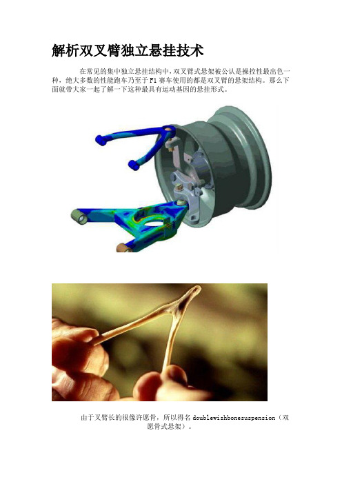
解析双叉臂独立悬挂技术在常见的集中独立悬挂结构中,双叉臂式悬架被公认是操控性最出色一种,绝大多数的性能跑车乃至于F1赛车使用的都是双叉臂的悬架结构。
那么下面就带大家一起了解一下这种最具有运动基因的悬挂形式。
由于叉臂长的很像许愿骨,所以得名doublewishbonesuspension(双愿骨式悬架)。
双叉臂悬挂也叫做双A臂悬挂或者双摇臂悬挂,属于双横臂悬架中的一种,英文名为doublewishbonesuspension(双愿骨式悬架),这个名字据说来源于西方圣诞节上一种吃火鸡的习俗,当人们开始吃的时候,首先要对火鸡身上一根V字形的骨头许愿,而这根骨头就叫许愿骨(Wishbone)。
而因为在双叉臂悬架结构中的A臂或者是V臂和许愿骨的形状非常相似,故得名双愿骨(doublewishbone)式悬架。
packard120是首款使用了双叉臂悬挂的量产车双叉臂悬架最早出现于上世纪30年代,当时的方程式赛车已经开始使用类似双叉臂的悬挂结构,而1935年,来自美国底特律的packard在旗下车型packard120上首次使用了双叉臂悬挂,作为当时豪华汽车的代表,pachard创造性的在量产车上首次使用了这种结构复杂的悬架,从而提升车辆的操控性能。
时至今日,双叉臂悬挂仍旧在除了各种性能跑车、豪华轿车和大型SUV上广泛使用。
关于双叉臂悬架起源的误区:此前,在网络上流传着一种错误的说法,认为双叉臂悬挂的灵感来自于麦弗逊悬挂,是由麦弗逊悬挂改进得来的。
这个说法的根据就是双叉臂悬挂和麦弗逊悬挂都拥有相似的A字形下摆臂和支柱式减震器的结构,所不同的是双叉臂结构在减震器上方还增加了连接车轮的A臂。
不过在事实上,双叉臂悬挂和麦弗逊悬挂并没有任何亲缘关系。
为何这么说呢?前面我们说过,早在上世纪30年代,双叉臂悬挂就已经开始在赛车运动上大量使用,而1935年则首次被使用在了量产的商品车上,而麦弗逊悬挂开始研发的时间为上世纪30年代中期,其设计灵感则是来源于飞机的起落架,而首次出现在商品车上则是在1949年的福特Vedette上。
- 1、下载文档前请自行甄别文档内容的完整性,平台不提供额外的编辑、内容补充、找答案等附加服务。
- 2、"仅部分预览"的文档,不可在线预览部分如存在完整性等问题,可反馈申请退款(可完整预览的文档不适用该条件!)。
- 3、如文档侵犯您的权益,请联系客服反馈,我们会尽快为您处理(人工客服工作时间:9:00-18:30)。
Technical analysis - FRIC suspension systems explainedMcLaren racing director Eric Boullier recently confirmed that the teams were sent a technical directive from the FIA's race director Charlie Whiting following the last race in Great Britain regarding the legality of the Front-and-Rear Interconnected Suspension (FRIC) systems used on most cars. The governing body is understood to believe that some of the systems currently being used may contravene the technical regulations, raising the possibility of them being banned outright. But what exactly is FRIC suspension and how does it work? Read on to find out…A Front-and-Rear Interconnected Suspension (FRIC) system, as shown on the 2013 Mercedes F1 W04Front-and-Rear Interconnected Suspension (FRIC) systems have been around for many years; for example Ferrari were one of several teams to run a cable-based system in the 1970s. However, the hydraulics-operated technology of today is much m ore complicated and can be ‘plumbed’ in many different ways - it can cross link the front suspension, cross link the rear suspension, link the front and rear suspension, or - in the most sophisticated systems - link all four corners diagonally for maximum performance benefit.But why do so many teams use FRIC systems? The first and most important reason is that it can help to generate more underbody downforce as it gives a degree of control over how the car changes attitude at speed when downforce is increasing. It also allows some degree of ride height/rake control when the car is braking.Formula One cars produce up to 6G of braking force which means that the load transfer from rear to front is around 300 kilos. This extra weight - there for around one second on corner approach - not only increases the load on the front tyres, it also decreases the load on the rear tyres, and this makes the rear unstable under braking and on corner entry.The other problem with this weight transfer from a performance point of view is the aerodynamic changes that take place when the car changes attitude. The weight transfer causes the front of the car to get closer to the ground and the rear to get further away and, with normal aero-maps, this will increase front downforce and decrease rear downforce, adding to instability.If you have a system - like FRIC - that can use the increased load on the front suspension under braking to lower the rear ride height then it is possible to have a much more aggressive underbody and front wing aero-map, which in turn increases the car’s overall downforce and therefore grip.If the system is sophisticated enough to also allow fluid to be displaced diagonally across the car it also allows the car to be run with much softer suspension without the penalty of increased roll. Again, this will help with overall aerodynamic grip and allow the driver to be much more aggressive over the kerbs.Most teams keep these sort of systems under wraps so it is difficult to define all the components in detail, but it general they consist of four actuators, one on each corner of the car (the locations of which are indicated by arrows 1 and 2 in this drawing of the 2013 Mercedes F1 W04), with hydraulic pipework connecting the four suspension units to a main accumulator (indicated by arrow 3) which is situated next to a control manifold (indicated by arrow 4).The main accumulator and the valve system within it acts as the brains behind the system. However, the systems utilised by each team will vary considerably with regard to how they use the displaced hydraulic fluid from each actuator andwhether they feed it through to another actuator either diagonally or inline.In the rear detail image you can see two black actuators with the pipe work linking them to a central accumulator (indicated by the red arrow). As you can see in the main image, pipework then links this to the main accumulator.In the front detail view (to the right of the main image) you can see the front two actuators inside the chassis (top two red arrows) with two pipes coming from them (middle pair of red arrows). These pipes are used to bleed and pressurise the system with dry break couplings (the lower pair of red arrows).In the lower detail image, the forward two red arrows show the positioning of the main accumulator and control manifold linking the front and rear suspension, whilst the two rearward red arrows show the positioning of the right-rear actuator and central accumulator.。