中性压力记录仪使用说明书
SIKA Type L 压力参考仪用户手册说明书

Pressure ReferenceType LUSER MANUAL ArrayREF TYPE L has two operating keys.The left key (SELECT) serves to select the functions andthe pressure units.The right key (ENTER) activates the selected function orpressure unit. The right key is also used toswitch between the Max.- and Min.-value.Turn-on:Pressing the SELECT key turns the instrument on. The instrument first displays the software version (year/week) and the fullscale pressure range. The instrument is then ready for use and indicates the actual pressure (top display) and the last measured Max.-value (bottom display).The instrument has the following functions:RESET: Max.-/Min.-value are set to the actual pressureOFF: Turns off the instrumentMANO: Releases the following functions:ZERO SEt: Sets a new Zero referenceZERO rES: Sets the Zero to factory settingCONT on: Deactivates the automatic turn-off functionCONT off: Activates the automatic turn-off function (the instrumentturns off 15 minutes after the last key function)followed by the unit selection: bar, mbar, hPa, kPa, MPa, PSI,kp/cm2, cmH2O, mH2O, inH2O, ftH2O, mmHg, inHgExample: Setting a new pressure unit (mbar):--> Turn on the instrument by shortly pressing the SELECT-key.--> Wait for the instrument’s measuring mode (approx. 3 seconds).--> Press the SELECT-key 3 times: MANO appears.--> Press ENTER: ZERO SEt appears.--> Press SELECT: ZERO rES appears.--> Press SELECT: CONT on or CONT off appears.--> Press SELECT: bar appears.--> Press SELECT: mbar appears.--> Press ENTER: The new pressure unit (mbar) is set.The instrument returns to the measuring mode.Display of the minimum pressure value:When in the measuring mode (Display: Actual Pressure and Max.- value), you may display the Min.-value for 5 seconds by shortly pressing the ENTER-key.Notes:• The functions and units can also be called up by keeping the SELECT-key depressed. Releasing the key enables the displayed function or unit to be activated with the ENTER-key.• If the selected function or unit is not activated within 5 seconds with the ENTER-key,REF TYPE L returns to the measuring mode without changing any settings.• Turning REF TYPE L on and off does not influence any of the previous settings.• If the CONT on function is activated, it is indicated with a flashing sign (cont) on the display.• If a pressure can not be represented on the display, OFL (overflow) or UFL (underflow) appears on the display.• If the actual pressure goes beyond the measuring range, the last valid pressure value starts flashing on the display.Installation:Screw the G1/4 male port of REF TYPE L into the female pressure port and tighten using the lower hexagon of the transducer. Loosen the upper hexagon and rotate the REF TYPE L to the desired position.Restraighten:The face of REF TYPE L can be rotated through 355°. This feature allows the REF TYPE L to be mounted in all possible positions; vertical, horizontal or upside down.Battery Change / Battery Life:When the battery starts weakening, a low battery warning will appear (BAT LOW). Battery change (turn off the instrument before changing the battery!):Open the battery compartment and change the battery (type CR 2430). Make sure that the O-ring remains embedded in the cover. The battery life is 2000 hours in normal measuring mode. Ranges / Calibration:The factory setting of the Zero for the ranges ≤61 bar is at 0 bar absolute. For sealed gauge pressure measurements, activate “ZERO SEt” at ambient pressure.Instruments with ranges >61 bar are calibrated in a sealed gauge mode at ambient pressure.Interface (RS485):The interface converter K103A (RS232) or K104A (USB) can be connected at the back of the manometer, allowing the data transfer to the PC.。
中性压力记录仪使用说明书英文版

CONTENTSChapter 1 Summarize. (2)Chapter 2Main features (2)Chapter 3Performance index......................................................... .3 Chapter 4 Contour dimension (4)Chapter 5Installation (5)1、Direct-connected (6)2、Trestle installation (7)Chapter 6Keypad instructions (8)Chapter 7 Operation (9)1、Time setting (9)2、Interrecord-gap setting (11)3、The number of storing data query (13)4、Data file name Settings (13)5、Zero correction (14)6、Full-range correction (14)7、Start/stop recording (15)8、Read data…………………………………………………..…………… ..169、Instrument calibration.............. . (17)10、Battery replacement (18)Chapter 8 Management software using (19)Chapter 9 Failure analysis and ruled out (26)Chapter 10 Maintenance and transportation (26)1、Maintenance (26)2、Transportation and storage (26)Chapter 1 SummarizePressure Recorder is a kind of electronic data record device which specially detects the pressure of a pipe or a pressure vessel .It sets the sensor, intelligent instrument at an organic whole, can collect and record pressure data according to the setted pressure record time interval. Pressure data can display through the liquid crystal , also can be read to the computer through USB, and cooperate with PC management software to statistics and analyse the data.Chapter 2 Main featuresPaperless、Low power consumptionSmall in size、High integrated、For easy installationLiquid crystal display measured pressure value and historical data on siteTime interval of pressure record: 1 second-18 hours、Can input configuration via keyboardRecord the most up to 10 years of history pressure dataBuilt-in high-capacity storage to store data , Can store 20000 dataRead data via U-diskChapter 3Performance indexAmbient temperature:-20~60℃Ambient humidity:10%~95%Process fluid measured:noncorrosive gas、liquid Precision:0.5 degreeGrade of waterproof:IP65Grade of explosive-proof:ExibⅡBT4Chapter 4 Contour dimensionUnit:mmChapter 5InstallationPressure recorder is linked with joining pipe through the thread interface, the connection need to install needle valve to be convenient to debugging, replacement and maintenance.Measuring installation points should as far as possible to avoid the interference of environmental factors, such as severe temperature changing, vibration and impact etc.The thread interface of Pressure recorder is M20 x 1.5, currently two installations are recommended: ①the Pressure recorder directly linked with the needle valve ; ② the Pressure recorder installed in the wall with stents (or tubes of curved stents or tubes of flat stents), and then connects to needle valve.It is shown as Figure 5.1 below:Figure 5.11、Direct-connectedWhen it is Direct connection, needle valve interfaces are allowed to be linked with two types of threaded interface through Adapter, metric thread M20 x 1.5 and 1/2 NPT thread.Installation procedures are as follows:1) When the meter needle valve interface is M20 x 1.5Ⅰ Install the needle valve in the pressure tap to make sure that the joint takes good seal and needle valve is in the closed position;ⅡInstall Pressure recorder, the interface of Pressure recorder and the interface of the stop valve are sealed via seal gasket;ⅢOpen the stop valve, observe the indicating value of Pressure recorder and set the Pressure recorder.2) When the meter needle valve interface is 1/2 NPTⅠ Select NPT thread adapter (optional), install it in the interface of Pressure recorder;ⅡInstall the needle valve in the pressure tap to make sure that the joint takes good seal and needle valve is in the closed position;Ⅲ Install Pressure recorder,wind the adhesive tape between the interface of Pressure recorder and the meter needle valve interfaceⅣ Open the needle valve, observe the indicating value of Pressure recorder and set the Pressure recorder.2、Trestle installationⅠConfirm the installation position ofPressure recorder, fasten Pressure recorder;ⅡConfirm catheter trend and length accordingto the distance between installation positionand Pressure tapping point , and site equipmentdistribution;ⅢCheck whether pressure tapping point takesgood sealing;ⅣChoose stainless steel pipe whose diameteris 6 as joining pipe to bend.ⅤConnect joining pipe with the interface ofPressure recorder ’s guardstaple;Figure 5.2ⅥCheck the sealing, open needle valve, observethe indicating value of Pressure recorder andmake the function setting. It is shown as Figure5.2.Chapter 6Keypad instructions①Calibration key: Calibrate instrument when theprecision is incorrect②Data read key:Read pressure data with U-disk.③Start key: start/stop recording pressure data④Up key:Used to scroll the numerical values up.⑤Setting key:Used to set the parameters⑥Down key:Used to scroll the numerical valuesdown⑦Reset key:Troubleshooting, data resetChapter 7 Operation1、Time settingThe pressure data recorded include time information,this time information is from the internal clock unit of the instrument,after long time running this clock unit will have error,regular adjustment is necessary,to the users who require exact time it is necessary to adjust once two months.It must be adjusted after replacing the battery or power off.The method is as follows:Menus and symbols instructions:Displayed symbol Meaningenter to setyaar settingmonth settingday settinghour settingminute settingsecond settingexit setup2、Recording interval settingThis instrument has the function of recording pressure data, recording mode is constantduration recording,the interval can be adjusted between 1 second to 18 hours.The method is as follows:Menus and symbols instructions:Displayed symbol Meaningenter to setrecording interval settinghour settingminute settingsecond settingexut setup3、The number of storing data queryPress "■" for half a second, show “1t1” , and loosen the key. Press "▼"for half a second, show"2 In", and loosen the button. Press "▼" for half a second, show "3 AC", loosen the button. P ress "■" for half a second, the instrument shows the following menu: , forexample: instrument shows r 0050,indicate that the recorder has recorded 50 data.Press "■"for half a second, show"EC", and loosen the key, instrument exit number query, the recorder switch to the screen of normal pressure value automatically.4、Data file name SettingPress "■"for half a second, show“1t1”, and loosen the button. Press "▼" for half a second, show "2 In", and loosen the button. Press "▼"for half a second, show "3 AC", loosen the button. Click“▼”again, show" 4 SA ". Press"■"for half a second, enter the interface of setup, show scene as follows, press "▲" to increase, press "▼" to decrease until to the required name. Press "■"for half a second, show"EC", and loosen the key, the instrument exit from set condition, data file name setting completed.Note: the data file name can only be four digits.5、Zero correctionPress "■" for half a second, show “1t1”, and loosen the button. Press "▼" until the screen shows “5 OP”. Press "■", show OP 0.0000, the "0.000" is zero, you can adjust the number via the direction key , press "■" until the accurate number, correction completed. And then into the measurement model, at this time the pressure value showed has been corrected.6、Full-range correctionFull-range correction not always made in the largest of the range,it can be corrected as long as the pressure is more than half range and less than or equal to full range, but the more close to the full range the better the correction result. When the value is less than half the range the correction operation is forbidden.During correction the pressure shoud be ensured stable and no changing.Press "■"to enter the menu, press "▼" until the "6SP" showed. And then press "■" t o enter full range correction. At this time the screen shows "SP00.00". The "00.00" is the pressure value before you entering the menu. Press "■"to enter the menu, press "▼" until the "6SP" showed.And then press "■" to enter full range correction. At this time the screen shows "SP00.00". The "00.00" is the pressure value before you enteringthe menu.The value may be different from the ideal value, you can adjust the value via the direction key , press "■" until the accurate number, correction completed. And then into the measurement model, at this time the pressure value showed has been corrected.Note: 1: During correction the pressure shoud be ensured stable and no changing.2: Zero correction would better be done before full range correction 3:When the value is less than half the range the correctionoperation is forbidden.7、Start/stop recordingStart/stop using the same button to complete, press this button continuously can switch between start and stop .When we need to record the data, press "start" for half a second, when the "rE" is showed the instrument enters into the data recording state and loosen the button, on the left of the screen shows"r", and pressure data on the rightWhen we need to stop data recording, also press"start" for half a second, when the"StoPrE"is showed , indicating the instrument exits from data recording state,loosen the "start" button, you will find "r" on the left of the screen disappeared, the right side is still normal pressure data.8、Read dataFirstly, exit from recording state,insert U-disk to USB interface, press "communication" button for half a second, when the instrument displays "CdPP" design, loosen the button, right now the instrument enters into the state of communication, and then screen shows "CH USb" said instrument is checking whether the USB is available, this process takes about one second, if it takes more than 5 seconds indicating that the instrument or U-disk may have a fault,press the reset button for five seconds ,then repeat the operations above three times, if it is still unavailable, generally we can judge that the U-disk has a problem, if the U-disk is normal before,we can judge that the instrument is unavailable.Please contact with t echnical section of our corporation, if the U-disk is of new type may indicate that the type of the U-disk is special so this instrument does not support, you can contact with t echnical section of our corporation as well.After checking, the instrument begin to write data, the screen displays "dI USb" .You should not press any button or shake the U-disk or pull it out during writing the data, please wait patient.If the screen always shows "dI USb", communication failure is suggested,you can handle it like the way introduced above. When the screen shows "dUEr" said that data successfully written to the U-disk, please waiting for its exiting from communication automatically. When the screen shows the normal pressure data,so you can pull it out,data-writing completed.Note: You can not operate the instrument during the communication state.9、Instrument calibrationTest the accuracy of the instrument regularly, when the precision is not accurate you can calibrate the instrument as follows:connect the instrument with standard pressure source, and the instrument takes multipoint calibration.Firstly, press "calibration" and "reset" for 1 second, loosen the "reset" button , loosen the "calibration" 2 seconds later,and wait for 2 seconds,then press "calibration" button, loosen the button when LCD screen appears "CAL", then press "start",at this time the screen shows four digitals (don't care about it), adjust the pressure source to 0 Mpa, press "calibration" for 1 second when the pressure is stable, loosen the key when the screen shows "P",at this time it back to four digitals state, and one point’s calibration completed.Then repeat these operations five times, and adjust the pressure to the value it lists each time,so you can complete the calibration of six points.It will show "PF" at last time, and the instrument exits from calibration automatically, press the" reset " key alone for 2 seconds, pressure can be collected normally 3 secondslater. Adjust pressure source to several different pressure values and observe the pressure values of the instrument, and compare these two values.If the error is not more than standard error so the instrument is qualified,otherwise calibrate once again until it’s qualified.10、Battery replacementThe battery of 3.6V supply power for the instrument ,it can normally continue 12 months, when the battery can not work normally the screen will appear "L_B_" design, it can work normally after replacing the battery. You must press "reset" for a second after installing a new battery.Chapter 8 Management software usingInstall the program: the software do n’t need to install,copy the directory and content to the computer,so it can be used, the name of the file is "historical data analysis 2.5. exe".Run the program: double click the "historical data analysis2.5.exe ", the program will run as shown in figure 8.1.Figure 8.1 program directoryAfter starting the program appears the interface as shown in figure 8.2Figure 8.2 Program interface.Prepare the original data: The datas read from the instrument store in the root directory of the U-disk. Copy this file to the computer, users can decide the storage location.Convert file: The software convert the original datas read from the U-disk to curve and data list, click the “import”as shown in figure 8.3 below, the red elliptical button is that.Figure 8.3 Convert file operationClick the button, there will be a window of "open file” , suggesting you choose the files you need to convert, this file is the original datas you stored on the last step, choose it and click " open ".The program start converting automatically, this process may take 1 minute the most. Please don’t operate the computer at this time.Figure 8.4 Choose the original fileFigure 8.5 File conversionFigure 8.6 Conversion completedRead data:1. Select the Period of time you want to see in the user-defined dialog as the chart shown below. Note: starting time is no more than the endingtimeThe software will screen out the maximum value, the time of themaximum value, the minimum value and the time of the minimum valueautomatically.2. Left click on to magnify the curve, observe the differences between the two images above and below, we can see that the image below is sparser than the image above.Figure 8.7 Magnified curve3. Similarly click ,image become dense as below.Figure 8.8 Shrunken curveGenerate EXCEL filesClick the “export” on the upper left corner of the window as the figure 8.9 shows:Figure 8.9 EXCEL formThe storage location of the EXCEL file can be decided by users.Chapter 9 Failure analysis and ruled outIf the pressure value of the instrument keep invariant or buttons can't be operated or screen garbled during the process,it indicates that the internal system is halted. You should press the "reset" for more than 1 second,so the instrument can recover normal using.The Pressure recorder should avoid strong impact and directly sunlight on LCD screen during the process. The ambient conditions should as far as possible avoid the interference of strong electromagnetic and severely mechanical vibration.The instrument shouldn't work under overvoltage,that will lead to permanent damage of sensor.Chapter 10 Maintenance and transportation1、Maintenance1)The instrument should regularly be checked in accordance withthe national standards to achieve the normal accuracy;2)Clean the shell of the instrument regularly to ensure thecleanliness of the instrument;3)The instrument should be kept away from collision during therunning process;2、Transportation and storage1)Excessive collision to the instrument is strictly prohibited during the shipment process;2)The instrument should be away from rains;3)The ambient temperature of transportation and storage: -50℃~+85℃.。
达威仪器 Series DLP 压力数据记录仪说明书

The Series DLP is a data logger that can record pressure andtemperature. The 1/4˝ NPT fitting comes standard and allows the loggerto be adapted to almost any pressure fitting. The internal temperaturesensor provides accurate temperature measurements without the needof a separate temperature recorder, and many of the models provide achoice between measuring pressure in PSIA or PSIG. The DL P caneasily be started and stopped from a PC or delayed to start up to sixmonths in advance. The battery-powered data logger can store over16,000 measurements per channel, and the easy to use DL700 softwaremakes retrieving data simple.SPECIFICATIONSRange: Temperature: -40 to 176°F (-40 to 80°C); Pressure: 0 to 30psia(g), 0 to 100 psia(g), 0 to 300 psia(g), 0 to 500 psia(g), 0 to 1000psia, and 0 to 5000 psia depending on the model.Memory Size: 16,383 readings per channel.Accuracy: Temperature: ±0.2°F (±0.1°C); Pressure: 2% FSR, 0.25%at 77°F (25°C) typical.Resolution: Temperature: 0.2°F (0.1°C); Pressure: 0.002 psia(g),0.005 psia(g), 0.05 psia(g), 0.05 psia, and 0.2 psia depending on themodel.Sampling Method:Stop on memory full.Sampling Rate:Selectable from 2 sec to 12 hrs.Computer Requirements: Windows® 95, Windows® 98, Windows®2000, Windows® ME, Windows NT®, and Windows® XP operatingsystem, one free USB port.Power Requirements: User replaceable, 3.6V lithium battery.Battery Life: 1 year (approx).Interface:USB port (interface cable required).Material: Stainless steel.Weight: 12 oz (340 g).Agency Approvals: CE.Windows® and Windows NT®are registered trademarks of Microsoft.3.Once the snap-ring has been removed, press gently on the whitedisk to force one end up for easy removal.4. Use 9/16˝ (15 mm) wrench, or a non-slip grip, to remove the NPTend.5. Gently slide the circuit board from the metal case.6. Set the circuit board down and make note of the orientation of thebattery’s positive (+) terminal. The “+” indication is also on the circuit board.7. Remove the old battery and install the new battery noting theorientation of the positive (+) terminal.Depending on where you purchased the battery, the leads may not bebent correctly or at all. Follow the diagram below for bending the batteryleads properly.8. Repeat steps 5 through 1 in reverse order to complete installation.MAINTENANCEUpon final installation of the Series DL P Data L ogger, no routinemaintenance is required. The Series DL P is not field serviceable andshould be returned if repair is needed (field repair should not beattempted and may void warranty). Be sure to include a brief descriptionof the problem plus any relevant application notes. Contact customerservice to receive a Return Goods Authorization number beforeshipping.©Copyright 2009 Dwyer Instruments, Inc.Printed in U.S.A. 5/09FR# R6-443670-00 Rev. 1。
R2008S使用说明书
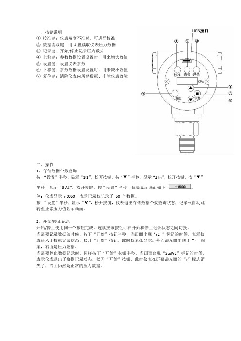
①校准键:仪表精度不准时,可进行校准
②数据读取键:用U盘读取仪表压力数据
③记录键:开始/停止记录压力数据
④上移键:参数数据设置设置时,用来增大数值
⑤设置键:设置仪表参数
⑥下移键:参数数据设置设置时,用来减小数值
⑦复位键:清除仪表内所存数据、排除仪表故障
二、操作
1、存储数据个数查询
按“设置”半秒,显示“1t1”,松开按键。
按“▼”半秒,显示“2 In”,松开按键。
按“▼”半秒,显示“3 AC”,松开按键。
按“设置”半秒,仪表显示画面如下。
例:仪表显示r 0050,表示记录仪记录了50 个数据。
按“设置”半秒,显示“EC”,松开按键,仪表退出存储数据个数查询状态,记录仪自动跳转至正常压力值显示画面。
2、开始/停止记录
开始/停止使用同一个按钮完成,连续按该按钮可在开始和停止记录状态之间切换。
当需要记录数据的时候,按下“开始”按钮半秒,当画面出现“rE ”标记的时候,表示仪表进入了数据记录状态,松开“开始”按钮,此时仪表在显示屏幕的最左面出现了“r”图案,右面是压力数据。
当需要停止数据记录时,同样按下“开始”按钮半秒,当画面出现“StoPrE”标记的时候,表示仪表退出了数据记录状态,松开“开始”按钮,此时仪表在屏幕最左面的“r”标志消
失了,右面仍然是正常的压力数据。
Omega PR 系列压力 温度数据记录仪用户指南说明书

e-mail:**************For latest product manuals:OM-PR SERIESPressure/TemperatureShop online at ®User’s Guide***********************Servicing North America:U.S.A.:Omega Engineering, Inc., One Omega Drive, P.O. Box 4047S tamford, CT 06907-0047 USAToll-Free: 1-800-826-6342 (USA & Canada only)Customer Service: 1-800-622-2378 (USA & Canada only)Engineering Service: 1-800-872-9436 (USA & Canada only)Tel: (203) 359-1660 Fax: (203) 359-7700e-mail:**************Canada:T oll-Free: 1-800-826-6342 (USA & Canada only)Tel: (514) 856-6928 Fax: (514) 856-6886e-mail:********************Web: www.omega.caServicing Mexico and Latin America:Mexico/Tel: 001-800-099-0420 (Mexico Only) Tel: 001-203-357-7577 (Outside Mexico) Latin America:Fax: 001- 203-968-7290 e-mail:***************.comWeb: Servicing Asia:China:Hotline: (+86) 800 819 0559, (+86) 400 619 0559e-mail:*************.com Web: Servicing Europe:France:Freephone: 0805 541 038 (France only)Tel: 01 57 32 48 17 Fax: 01 57 32 48 18e-mail:***************Web: www.omega.frGermany/A ustria:F reephone************(Germanyonly)Tel: +49 (0)7056-9398-0 Fax: +49 (0)7056-9398-29e-mail:*************Web: www.omega.deItaly:Freephone: 800 906 907 (Italy Only)Tel: +39 022 333 1521 Fax: +39 022 333 1522e-mail:********************.com Web: Netherlands:Freephone: 0800 099 33 44 (Netherlands only)Benelux Tel: +31 070 770 3815 Fax: +31 070 770 3816e-mail:***************Web: www.omega.nlSpain:Freephone: 800 900 532 (Spain only)Tel: +34 911 776 121 Fax: +34 911 776 122e-mail:***************.com Web: United Kingdom:Freephone: 0800 488 488 (United Kingdom only)Tel: +44 (0)161 777 6611 Fax: +44 (0)161 777 6622e-mail:**************.uk Web: The information contained in this document is believed to be correct, but OMEGA accepts no liability for any errors it contains, and reserves the right to alter specifications without notice.OM-PR Series Pressure Temperature LoggerThe Pressure Temperature Logger is a sealed (IP67) Data Logger used formeasuring air or liquid pressure and ambient temperature. The unit is selfcontained in a small 316L stainless steel enclosure with a threaded ¼” NPT portto connect to a pressure source. The Logger can operate unattended for monthsor years. Recording parameters can be set in the Windows®PC Software. Theunit can be set to record on instantly, at preset times, or on alarm conditions. Upto 64,000 readings can be saved in non-volatile memory at intervals from 2seconds to 24 hours. Internally there is a USB port for direct connection to alaptop or PC, and a button and LED for user interaction as described below.Installation: The logger screws into a ¼” NPT port. Use suitable tape or threadsealant/dope on the threads before inserting the logger into the port. Use anadjustable wrench on the nut to tighten the device into the port and test for leaks. Access: To access the internals of the unit it is necessary to unscrew the lid (counterclockwise). This exposes the control panel shown below. The function of the parts is as follows:Push Button/LED functionality:The push button can beused to check status or to change the state of the data logger.For instance, it can be used to start and stop recording, ifdesired. This feature can also be disabled to ensure the datalogger state remains unchanged until connected to a PC.TO CHECK STATUSShort press and release: LED will flash in various patterns toindicate data logger status:The flash sequence is: Battery status > Record status >Alarm statusOne long red flash at the beginning of the flash sequence indicates low battery. (no red flash = battery ok) One long red flash at the end of the flash sequence indicates an alarm. (no red flash = no alarm)Slow red/green blink: Connect to PC. Unit is NOT set up or memory is full.TO CHANGE STATEPress and hold button, release when LED turns steady green: Changes record state on/offPress and hold button, release when LED turns steady red: Reset alarm indicationPress and hold button, release after LED goes off: No changeThe table below summarizes the push-button / LED functionality.Serial Communication: The logger has a mini USB port. Plug the cable into this port and the other end into the USB port on your PC/Laptop. The provided software needs to be installed in order to work with the logger.Battery: Replace the battery as needed with type: ER14250 3.6V Lithium - Tadiran TL-5902 or similar (Omega part no. OM-PR-BATT). Remove threaded cap and insert battery as shown in diagram below (observe polarity):STATUSLED SequenceLow battery - one RED blink (No red if battery OK)Recording or triggered to record - fast GREEN /RED blinkIdle/Not recording - one long GREEN blinkAlarm occurred - one long RED blink (No red if no alarm) Not set up or memory full - slow RED /GREEN blink, connect to PCRESULT OF BUTTON RELEASELED patternRelease button while LED GREEN - Turn record mode on/off*Release button while LED RED - Reset alarm indication*Release button when LED goes off - No change *NOTE: Feature must be enabled in softwareSTATUS —Press & Release ButtonLED PatternLo Batt. >>>> Record >>>>>AlarmCHANGE STATE —Press & Hold ButtonReleaseReleaseRelease after LED’s go offWARRANTY/DISCLAIMEROMEGA ENGINEERING, INC. warrants this unit to be free of defects in materials and workmanship for a period of 13 months from date of purchase. OMEGA’s WARRANTY adds an additional one (1) month grace period to the normal one (1) year product warranty to cover handling and shipping time. This ensures that OMEGA’s customers receive maximum coverage on each product.If the unit malfunctions, it must be returnedto the factory for evaluation. OMEGA’s Customer Service Department will issue an Authorized Return (AR) number immediately upon phone or written request. Upon examination by OMEGA, if the unit is found to be defective, it will be repaired or replaced at no charge. OMEGA’s WARRANTY does not apply to defects resulting from any action of the purchaser, including but not limited to mishandling, improper interfacing, operation outside of design limits, improper repair, or unauthorized modification. This WARRANTY is VOID if the unit shows evidence of having been tampered with or shows evidence of having been damaged as a result of excessive corrosion; or current, heat, moisture or vibration; improper specification; misapplication; misuse or other operating conditions outside of OMEGA’s control. Components in which wear is not warranted, include but are not limited to contact points, fuses, and triacs.OMEGA is pleased to offer suggestions on the use of its various products. However, OMEGA neither assumes responsibility for any omissions or errors nor assumes liability for any damages that result from the use of its products in accordance with information provided by OMEGA, either verbal or written. OMEGA warrants only that the parts manufactured by the company will be as specified and free of defects. OMEGA MAKES NO OTHER WARRANTIES OR REPRESENTATIONS OF ANY KIND WHATSOEVER, EXPRESSED OR IMPLIED, EXCEPT THAT OF TITLE, AND ALL IMPLIED WARRANTIES INCLUDING ANY WARRANTY OF MERCHANTABILITY AND FITNESS FOR A PARTICULAR PURPOSE ARE HEREBY DISCLAIMED. LIMITATION OF LIABILITY: The remedies of purchaser set forth herein are exclusive, and the total liability of OMEGA with respect to this order, whether based on contract, warranty, negligence, indemnification, strict liability or otherwise, shall not exceed the purchase price of the component upon which liability is based. In no event shall OMEGA be liable for consequential, incidental or special damages.CONDITIONS: Equipment sold by OMEGA is not intended to be used, nor shall it be used: (1) as a “Basic Component” under 10 CFR 21 (NRC), used in or with any nuclear installation or activity; or (2) in medical applications or used on humans. Should any Product(s) be used in or with any nuclear installation or activity, medical application, used on humans, or misused in any way, OMEGA assumes no responsibility as set forth in our basic WARRANTY /DISCLAIMER language, and, additionally, purchaser will indemnify OMEGA and hold OMEGA harmless from any liability or damage whatsoever arising out of the use of the Product(s) in such a manner.OMEGA’s policy is to make running changes, not model changes, whenever an improvement is possible. This affords our customers the latest in technology and engineering.OMEGA is a registered trademark of OMEGA ENGINEERING, INC.© Copyright 2013 OMEGA ENGINEERING, INC. All rights reserved. This document may not be copied, photocopied, reproduced, translated, or reduced to any electronic medium or machine-readable form, in whole or in part, without the FOR WARRANTY RETURNS, please have the following information available BEFORE contacting OMEGA:1. P urchase Order number under which the product was PURCHASED,2. M odel and serial number of the product under warranty, and3. Repair instructions and/or specific problems relative to the product.FOR NON-WARRANTY REPAIRS, consult OMEGA for current repair charges. Have the followinginformation available BEFORE contacting OMEGA:1. Purchase Order number to cover the COST of the repair,2. Model and serial number of the product, and3. Repair instructions and/or specific problems relative to the product.RETURN REQUESTS/INQUIRIESDirect all warranty and repair requests/inquiries to the OMEGA Customer Service Department. BEFORE RETURNING ANY PRODUCT(S) TO OMEGA, PURCHASER MUST OBTAIN AN AUTHORIZED RETURN (AR) NUMBER FROM OMEGA’S CUSTOMER SERVICE DEPARTMENT (IN ORDER TO AVOID PROCESSING DELAYS). The assigned AR number should then be marked on the outside of the return package and on any correspondence.The purchaser is responsible for shipping charges, freight, insurance and proper packaging to prevent breakage in transit.Where Do I Find Everything I Need for Process Measurement and Control?OMEGA…Of Course!Shop online at SMTEMPERATUREⅪߜThermocouple, RTD & Thermistor Probes, Connectors, Panels & AssembliesⅪߜWire: Thermocouple, RTD & ThermistorⅪߜCalibrators & Ice Point ReferencesⅪߜRecorders, Controllers & Process MonitorsⅪߜInfrared PyrometersPRESSURE, STRAIN AND FORCEⅪߜTransducers & Strain GagesⅪߜLoad Cells & Pressure GagesⅪߜDisplacement TransducersⅪߜInstrumentation & AccessoriesFLOW/LEVELⅪߜRotameters, Gas Mass Flowmeters & Flow ComputersⅪߜAir Velocity IndicatorsⅪߜTurbine/Paddlewheel SystemsⅪߜTotalizers & Batch ControllerspH/CONDUCTIVITYⅪߜpH Electrodes, Testers & AccessoriesⅪߜBenchtop/Laboratory MetersⅪߜControllers, Calibrators, Simulators & PumpsⅪߜIndustrial pH & Conductivity EquipmentDATA ACQUISITIONⅪߜData Acquisition & Engineering SoftwareⅪߜCommunications-Based Acquisition SystemsⅪߜPlug-in Cards for Apple, IBM & CompatiblesⅪߜData Logging SystemsⅪߜRecorders, Printers & PlottersHEATERSⅪߜHeating CableⅪߜCartridge & Strip HeatersⅪߜImmersion & Band HeatersⅪߜFlexible HeatersⅪߜLaboratory HeatersENVIRONMENTALMONITORING AND CONTROLⅪߜMetering & Control InstrumentationⅪߜRefractometersⅪߜPumps & TubingⅪߜAir, Soil & Water MonitorsⅪߜIndustrial Water & Wastewater TreatmentⅪߜpH, Conductivity & Dissolved Oxygen Instruments。
Omega OM-CP-PRTC210 温度与压力数据记录仪说明书

Thermocouple Temperature and Pressure Data LoggerU Up to 2 Years Battery Life U Wide Temperature Range U Accepts Thermocouple Types J, K, T, E, R, S, B and NU High Speed Download U Real-Time OperationU Programmable Start Time U Miniature SizeThe OM-CP-PRTC210 is a pressure and thermocouple temperature data logger, ideal for use in factory settings. This device is available from 2 to 345 bar (30 to 5000 psi) and features a 1⁄8 MNPT fitting for quick connection. The OM-CP-PRTC210 has areal-time clock and a battery lifeof up to 2 years. This all in onecompact, portable, easy to usedevice has a high-speed downloadand can measure and record up to10,922 readings per channel.The storage medium is non-volatile solid state memory, providing maximum data security even if the battery becomes discharged. The OM-CP-PRTC210 can be started and stopped directly from your computer and its small size allows it to fit almost anywhere.The OM-CP-PRTC210 makes data retrieval quick and easy. Simply plug it into an available COM port and our user-friendly software does the rest.The software converts a PC into a real-time strip chart recorder. Data can be printed in graphical and tabular format or exported to a text or Microsoft Excel ® file.SpecificationsINTERNAL CHANNEL Temperature Range:-20 to 80°C (-4 to 176°F)Temperature Resolution: 0.1°C Calibrated Accuracy: ±0.5°C REMOTE CHANNEL Thermocouple Types: J, K, T, E, R, S, B and N Thermocouple Connection:Female subminiature (SMP) connector Cold Junction Compensation: Automatic, based on internal channel Maximum Thermocouple Resistance: 1000Ω, <100Ω recommendedPressure Sensor: Semiconductor strain gauge Pressure Specified Accuracy: 2% FSR, 0.25% @ 25°C Typical Pressure Response Time: 0.1 ms (10 to 90% FSR)Pressure Connection: 1⁄8 MNPT Start Modes:Software programmable immediate start or delay start up six months in advanceReal-Time Recording:May be used with PC to monitor and record data in real time Memory: 10,922 readings per channel; software configurable memory wrapReading Rate: 2 seconds to 12 hours, selectable in software Calibration: Digital calibration through softwareCalibration Date: Automatically recorded within deviceOM-CP-PRTC210-30A shown larger than actual size.OM-CP-IFC200 Windows software displays data in graphical ortabular format.software (required to operate the data logger and is sold separately).To order data logger with NIST calibration certificate, add suffix “-CERT” to model number and add additional cost to price.Ordering Example: OM-CP-PRTC210-30A-CERT, thermocouple temperature and pressure data logger with NIST calibration certificate, and OM-CP-IFC200, Windows software.Battery Type: 3.6 V lithium battery (included), user replaceableBattery Life:Up to 2 years Data Format: Date and timestamped °C, °F, K, °R, °C, °F, °K,°R, mV; inH2O, psig, inHg, bar, atm, Torr, Pa, kPa, and MPa Time Accuracy:±1 minute/month (at 20 to 30°C)Computer Interface: PC serial or USB (interface cable required); 57,600 baud5SRTC/5LRTC Series. Software: XP SP3/Vista/7 and 8 (32-bit and 64-bit)Operating Environment: -20 to 80°C (-4 to 176°F), 0 to 95% RH non-condensing Dimensions:55 H x 63 W x 22 mm D (2.2 x 2.5 x 0.9") plus NPT fittingEnclosure: Delrin ®Weight: 119 g (4.2 oz)。
Omega HHP9303 压力记录仪手册说明书
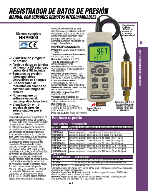
HHPS100-5 Sensor de presión conectable, 0 a 5 bares (0 a 72,5 psi)
HHPS100-10 Sensor de presión conectable, 0 a 10 bares (0 a 145 psi)
HHPS100-20 Sensor de presión conectable, 0 a 20 bares (0 a 290 psi)
Ejemplos de pedidos: HHP9303, registrador de datos de presión manual, HHPS100-2, sensor de presión de 0 a 2 bares (0 a 29 psi).
HHP9303, registrador de datos de presión manual, HHPS100-200, sensor de presión de 0 a 200 bares (0 a 2,900 psi) y SC-SD, estuche blor de presión/registrador de datos manual con tarjeta SD de 2 GB
SENSORES DE PRESIÓN
HHPS100-2 Sensor de presión conectable, 0 a 2 bares (0 a 29 psi)
U Sensores de presión intercambiables disponibles en 8 rangos
U Sin necesidad de recalibración cuando se cambian los rangos de presión
U No se requiere un software especial, descarga directa en Excel
3Q04说明书(2010.01.07new)
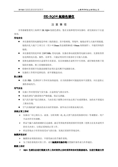
SK-3Q04氢焰色谱仪注 意 事 项非常感谢您使用上海神开SK-3Q04氢焰色谱仪,您在安装和使用本仪器时,请先阅读以下注意事项: 用电安全● 本仪器使用的电源线是单相三线的接法,其中除相线、零线外,地线必须与大地牢固接通,地线应扎入地下2米左右(用≥Ф20mm 的金属铁棒或≥30mm 角铁制作)。
不能用零线作地线。
● 本仪器使用的是单相220V50Hz 用电电源,仪器在移动或更换用电插头座时,先要检查供电电网的电压值、极性、功率等。
只能证明其符合要求时方可接入仪器。
● 更换电源保险丝时注意要符合其要求,其具体规格在说明书中可查到。
或仔细检查换下的保险丝规格,换上同规格保险丝。
● 检修时若需拆开仪器盖面板用必须注意先断开电源插头座。
● 仪器的工作程序是固化的,请不要随意改动。
防止烫伤● 仪器FID 、色谱柱炉工作时有加热温度,在关机检修时可能温度来不及散发,应注意防止烫伤事故发生。
用气安全● 仪器工作时使用氢气发生器,注意将氢气排出室外。
● 快速色谱仪气路系统应严格检漏,保证无泄漏。
● 氢气发生器产氢后消耗水,当水位低于报警点时应加去离子水或蒸馏水。
加的水不要超出上限水位线。
● 空气压缩机储气桶内的水应该经常放掉,放毕水后应将放水阀关闭。
系统正常工作时仪器出厂时已将压力、流量、分析周期(C 1-C 5 样品气输入端的玻璃砂芯过滤球、滤芯等预处理系统需要经常更换(更换方法见本说明书的有关内容),以保证系统的正常工作。
天然气组份的保留时间)等调整好,用户不必再作任何调整。
样品管线由于经常容易受水气的污染,发现后需要作管线反吹。
触摸屏设定时触摸屏必须保持清洁,不要用油污的手操作系统。
为了保持系统的可靠工作,请用触摸屏的操作笔设置操作条件或与外界通信。
数据上传时3Q04色谱仪在进行数据文件上传时将停止实时采样和实时的数据通讯,仅进行数据文件的传输;3Q04传输完数据文件后自动恢复到正常工作状态;在正常工作状态下不要进行文件传输,防止漏测资料。
- 1、下载文档前请自行甄别文档内容的完整性,平台不提供额外的编辑、内容补充、找答案等附加服务。
- 2、"仅部分预览"的文档,不可在线预览部分如存在完整性等问题,可反馈申请退款(可完整预览的文档不适用该条件!)。
- 3、如文档侵犯您的权益,请联系客服反馈,我们会尽快为您处理(人工客服工作时间:9:00-18:30)。
目录一、概述. (3)二、主要特点 (3)三、性能指标 (4)四、外形尺寸 (5)五、安装 (6)1、直接连接 (7)2、支架安装 (8)六、按键说明 (9)七、操作 (10)1、时间设定 (10)2、记录间隔设置 (12)3、存储数据个数查询 (14)4、数据文件名设置 (14)5、零点修正 (15)6、满量程修正 (15)7、开始/停止记录 (16)8、读取数据 (17)9、仪表校准.............. . (18)10、电池更换 (19)八、管理软件使用.......... .. (20)九、故障分析及排除 (27)十、维护及运输 (28)1、维护 (28)2、运输、储藏 (29)一、概述压力记录仪是专门对管道或压力容器进行压力监测的电子数据记录装置。
它集传感器、智能仪表于一体,能够按照设定的压力记录时间间隔采集、记录压力数据。
压力数据可通过现场液晶显示,也可通过优盘读取到计算机上,配合上位机管理软件,对数据进行统计、分析。
二、主要特点无纸化、低功耗体积小、集成度高、便于安装现场液晶显示实测压力值和历史数据压力记录时间间隔:1秒--18小时,可有键盘输入组态记录最多达10年的历史压力数据内置大容量存储器存储数据,可存储20000个数据通用U盘读取数据三、性能指标环境温度:-20~60℃环境湿度:10%~95%被测介质:非腐蚀性气体、液体 精确度:0.5级防水等级:IP65防爆等级:ExibⅡBT4四、外形尺寸单位:mm五、安装压力记录仪通过螺纹接口与引压管相连,连接处需安装仪表针阀,方便仪表调试、更换和维修。
应尽量使测量安装点避免环境因素的干扰,如剧烈的温度变化、振动和冲击等。
压力记录仪的螺纹接口为M20×1.5,目前推荐两种安装方式:①压力记录仪直接与仪表针阀相连接;②压力记录仪安装在墙装支架(或管装弯支架或管装平支架)上,然后连接到仪表针阀上。
见图5.1图5.11、直接连接直接连接时仪表针阀接口允许通过转接头与两种螺纹接口连接,公制螺纹M20×1.5和1/2NPT螺纹。
安装步骤如下:1)当仪表针阀接口为M20×1.5时Ⅰ将仪表针阀安装在管道的取压接头上,确保密封良好,仪表针阀处于关闭状态;Ⅱ安装压力记录仪,压力记录仪接口与截止阀接口之间通过密封垫片密封;Ⅲ打开截止阀,观察压力记录仪的示值并进行压力记录仪设置。
2)当仪表针阀接口为1/2NPT时Ⅰ选取NPT螺纹转接头(订货时选配),安装在压力记录仪接口上;Ⅱ将仪表针阀安装在管道的取压接头上,确保密封良好,仪表针阀处于关闭状态;Ⅲ安装压力记录仪,压力记录仪接口与仪表针阀接口之间缠绕生胶带,保证密封良好;Ⅳ打开仪表针阀,观察压力记录仪的示值并进行压力记录仪设置。
2、支架安装Ⅰ确定压力记录仪的安装位置,固定压力记录仪;Ⅱ按照压力记录仪安装位置与取压点的距离及现场设备分布,确定导管走向及长度;Ⅲ检查取压点的密封性是否良好;Ⅳ选用外径为φ6的不锈钢管作引压管进行弯制;图5.2Ⅴ连接引压管与压力记录仪卡套接口;Ⅵ检查密封性,打开针阀,观察压力记录仪示值并进行功能设置。
①校准键:仪表精度不准时,可进行教准②数据读取键:用优盘读取仪表压力数据③开始键:开始/停止记录压力数据④上移键:参数数据设置设置时,用来减小数值⑤设置键:设置仪表参数⑥下移键:参数数据设置设置时,用来增大数值⑦复位键:故障排除,数据清零七、操作1、时间设定对于记录的压力数据有时间信息,该时间信息来自仪表内部的时钟单元,该时钟单元长时间运行后会有误差,需要定期调整,对于要求时间精确的用户可以2个月调整一次,也就是我们平时说的“对点儿”,更换电池或者掉电后必须要进行时间调整。
方法如下:画面及符号说明:显示符号意义进入设置功能年份设置月份设置日设置小时设置分钟设置秒设置设置完毕2、记录间隔设置该仪表具有压力数据记录功能,记录方式为按等间隔时间记录,该间隔是可以进行调整,调整的范围1秒~18小时。
方法如下:画面及符号说明:显示符号意义进入设置功能进入记录间隔设置小时设定分钟设定秒设定设置完毕3、存储数据个数查询按“设置”半秒,显示“1t1”,松开按键。
按“▼”半秒,显示“2 In”,松开按键。
按“▼”半秒,显示“3 AC”,松开按键。
按“设置”半秒,仪表显示画面如下例:仪表显示r 0050,表示记录仪记录了50个数据。
按“设置”半秒,显示“EC”,松开按键,仪表退出存储数据个数查询状态,记录仪自动跳转至正常压力值显示画面。
4、数据文件名设置按“设置”半秒,显示“1t1”,松开按键。
按“▼”半秒,显示“2 In”,松开按键。
按“▼”半秒,显示“3 AC”,松开按键。
按“▼”半秒,显示“3 AC”,松开按键。
再按一次“▼”,显示“4 SA”。
按“设置”半秒,进入设置界面,显示画面如下,按“▲”键是减小,按“▼”键是增加,直到设置到需要的文件名值。
按“设置”半秒,显示“EC”,松开按键,仪表自动退出设置状态,数据文件名设置完成。
注:数据文件名只能是四位数字。
5、零点修正按“设置”半秒,显示“1t1”,松开按键。
按“向下”键直到屏幕显示“5 OP”。
按设置键进入,显示OP 0.000,其中“0.000”就是零点,此时可以通过方向键输入实际压力值,按“确认”键。
既可以完成零点修正。
然后进入测量模式,此时显示的压力值就是经过零点修正的。
6 满量程修正满量程修正并不是一定要在最大量程的时候进行修正,只要是大于一半量程压力,小于等于满量程压力的时候都可以进行修正,但是越接近满量程压力修正的效果越好。
在小于一半量程压力时禁止进行该修正操作。
进入的时候保证压力稳定无明显变化。
按“确定”键进入菜单,按“向下”键直到屏幕出现“ 6SP”。
然后按“确定”键进入满量程修正操作。
此时屏幕出现“SP00.00”其中“00.00”是进入菜单前仪表显示的压力数值。
该数值可能和理想压力数值有差别,此时通过方向键调整到正确的数值,按“确认”键。
既可以完成修正。
然后进入测量模式,此时显示的压力值就是经过修正的。
注意:1:满量程修正时压力应稳定无明显变化。
2:进行满量程修正前,最好进行零点修正。
3:小于一半量程压力时禁止满量程校准。
7、开始/停止记录开始/停止使用同一个按钮完成,连续按该按钮可在开始和停止记录状态之间切换。
当需要记录数据的时候,按下“开始”按钮半秒,当画面出现“rE ”标记的时候,表示仪表进入了数据记录状态,松开“开始”按钮,此时仪表在显示屏幕的最左面出现了“r”图案,右面是压力数据。
当需要停止数据记录时,同样按下“开始”按钮半秒,当画面出现“StoPrE”标记的时候,表示仪表退出了数据记录状态,松开“开始”按钮,此时仪表在屏幕最左面的“r”标志消失了,右面仍然是正常的压力数据。
8、读取数据将优盘插入USB接口,按下“通讯”按钮半秒,当仪表显示屏上出现“CdPP”图案时,松开按钮,此时仪表进入通讯状态,然后屏幕显示“CH USb”表示仪表正在检查优盘是否可用,该过程大约需要一秒种,超过5秒说明仪表或者优盘有故障,按复位键后5秒重复上面的操作,如果3次复位后还是不能通过检查,可大致判断该优盘出现问题,如果是以前可以正常使用的优盘出现这样的问题,可判断是仪表的问题,联系我公司技术支持部门,如果是新型号的优盘,可能说明该优盘型号特殊,该仪表不支持,也可以和我公司的技术支持部门联系。
检查优盘阶段通过后,仪表开始写数据,屏幕显示为“dI USb”写数据的时候不可以操作仪表其他按钮,也不可以晃动优盘,更不能拔出优盘,耐心等待,如果屏幕显示“dI USb”始终不变,可认为通讯失败,处理方式同上面介绍的。
当屏幕显示“dUEr”表示数据成功写入优盘,等仪表自动退出通讯,屏幕显示正常的压力数据的时候,可以拔出优盘,完成数据读取。
注:仪表在通讯状态时,不能进行其他操作9、仪表校准定期检验仪表精度,精度不准确的时候可以进行校准,具体方法如下:连接标准压力源,仪表采取多点校准方法。
首先同时按下“校准”和“复位”键1秒,先松开“复位”键,2秒后松开“校准”键,再等待2秒后按下“校准”键,当液晶画面出现“CAL”时,松开按键,再按一下开始键,此时屏幕显示4位数字(不用关心),将压力源调整到0Mpa,压力稳定后,按下“校准”键1秒种,屏幕显示“P”松开该键,此时回到数字4位显示状态,此时完成了一点的校准,接下来重复该操作5次,每次将压力调整到上面所列的压力数值,即可完成六点的校准,最后一次会显示“PF”字样,然后仪表自动退出校准状态,再次单独按下“复位”键2秒,3秒后可以正常采集压力。
调整压力源到几个不同的压力数值,观察仪表的压力数值,然后做比较,不超过标准误差即合格。
如果超标,重复校准一次。
直到合格为准。
10、电池更换仪表使用3.6V电池供电,正常情况下可使用12个月,当电池电量低的不可以正常工作的时候,仪表屏幕会出现“L_B_”图案,更换电池后可正常使用,按装新电池后,必须按“复位”键一秒钟。
八、管理软件使用安装程序:该软件无须安装,将程序目录及内容复制到计算机里面,即可以使用了,文件的名称为“历史数据分析2.5.exe”。
运行程序:双击“历史数据分析2.5.exe”文件,程序就会运行。
如图8.1。
图8.1 程序目录程序启动以后,出现如图8.2所示的程序界面。
图8.2 程序界面准备数据原文件:从仪表读出的数据存放在优盘的根目录里面。
将该文件拷贝到计算机里面,存放位置用户自己决定。
转换文件该软件把从优盘里面读出的原文件转化成曲线及数据列表,点击程序左上角的按钮“导入”如图8.3所示,红色椭圆为该按钮图8.3 转换文件按钮操作点击按钮之后,会出现“打开”窗口,提示你选择需要转换的文件,该文件是上一步你存放的原文件,选择之后点“打开”。
程序开始自动转换,该过程可能需要1分钟以内的时间。
此时用户尽量不要操作电脑。
图8.4选择原文件图8.5 文件转换图8.6 转换完成查看数据:1、在(自定义显示输入)对话框选择所需察看数据段的时间,如下图:注意其中开始时间不大于结束时间软件将自动筛选出所察看时间段的最大值、最大值时刻、最小值及最小值时刻2、左键单击放大曲线,观察上下两图的差别,可以看出下图要比上图的曲线稀。
图8.7 曲线放大3、同理单击,图形变得稠密。
如下图所示。
图8.8 曲线缩小生成EXCEL文件点击程序左上角按键“导出”,如图8.9所示图8.9 EXCEL表格EXCEL文件的存放位置可由用户自己决定。
九、故障分析及排除如果仪表在使用过程中出现了压力数值始终不变,按钮无法操作,或者屏幕显示乱码情况,说明仪表内部死机,这时应该按下“复位”按钮1秒以上,仪表既可恢复正常使用。