电气设备操作说明书
施耐德电气 Easy UPS 3S 10-40 kVA 操作说明书

部件更换 ..................................................................................................40 确定是否需要更换部件 ........................................................................40
带内部电池和模块电池柜的 UPS 的推荐设置 ........................................34 设置生命周期监控..................................................................................... 36 设置......................................................................................................... 37
目录
10-40 kVA
重要安全说明- 请妥善保存这些说明 ......................................................5
电磁兼容性.................................................................................................6 安全注意事项 .............................................................................................6
电气设备使用说明
概述2X25000KV A硅铁炉工程是由中钢集团吉林机电设备有限公司设计,吸收了挪威埃肯公司的组合把持器技术,国内首家采用组合把持器技术冶炼硅铁,取得了良好的经济技术指标,创造了国内硅铁冶炼最低电耗。
设计形式为矮烟罩,旋转炉体半封闭固定式埋弧作业硅铁炉。
除尘系统是由武汉钢铁设计院设计,包括空气冷却器,旋风除尘器,布袋除尘器以及托架等设备。
该主体非标设备是集机械与电气于一体的先进自动化设施,通过调节器,PLC等电器设备控制信号或操作器,自动准确的执行系统给定的任务,使本主体非标设备工程技术性能及可靠性有了很大的提高。
本工程电气系统分为电炉控制部分和电炉变压器主回路部分,本说明只涉及电炉控制部分和电炉变压器本体及其相关操作部分。
电炉控制系统一.电极吹风A.相关电气设备1.五层动力柜位置:26米平台2.电极吹风控制箱位置:20米平台3.A相电极吹风电机(11 KW)位置:20米平台4. B相电极吹风电机(11 KW)位置:20米平台5. C相电极吹风电机(11 KW)位置:20米平台B.设备功能冷却电极,控制培烧速度,防止电极过烧。
C.操作使用1.在五层动力柜中闭合刀开关QS,然后分别闭合断路器QF1、QF2。
(注:QF13#炉电极吹风总电源,QF2为4#炉电极吹风总电源。
)2.电极吹风控制箱位于20米平台,其面板上设有:A相电极吹风启动/停止按钮、指示灯,B相电极吹风启动/停止按钮、指示灯,C 相电极吹风启动/停止按钮、指示灯。
启动/停止按钮控制电极吹风电机的运行和停止,正常工作时A、B、C三相电极吹风运行指示灯亮,停止工作时停止指示灯亮。
注:在操作台面板上也设有A、B、C三相电极吹风启动/停止按钮,功能同电极吹风控制箱上的同名按钮。
二.电极升降A.相关电气设备1.炉前电源柜位置:电炉仪表室2.电炉控制柜位置:电炉仪表室3.操作台位置:电炉仪表室4.工控机位置:电炉仪表室5.液压站控制箱位置:20米平台6. 1DK(铁壳开关)位置:20米平台7. 2DK(铁壳开关)位置:20米平台8.电炉信号屏位置:7米平台B.设备功能1.调节三相电极电流在工艺要求的范围内,并使之平衡,以达控制炉温、提高电效率的目的。
电气火灾监控设备 JBF-62S30 使用说明书

电气火灾监控设备JBF-62S30使用说明书在安装和使用本产品前务必仔细阅读和理解该使用说明书!青鸟消防股份有限公司Jade Bird Fire Co.,Ltd.目录第一章系统概述 (4)1.1 特点 (4)1.2 参数 (5)1.3 外形尺寸 (5)1.4 结构介绍 (6)1.5指示灯及按键 (7)1.6 执行标准 (7)第二章安装调试步骤 (8)2.1 系统安装要求 (8)2.2 接线说明 (8)2.3现场调试 (8)第三章监控设备主要功能 (10)第四章监控设备显示说明 (11)4.1 监控设备正常监视状态 (11)4.2监控报警信息 (11)第五章监控设备操作 (13)5.1系统查询 (13)5.1.1 查询注册地址 (13)5.1.2查询系统单元配置 (14)5.1.3 查询历史记录 (14)5.1.4 查询组网控制器 (15)5.1.5 查询注释信息 (15)5.1.6 查询部件参数 (15)5.1.7 查询分体式部件参数: (16)5.1.8 查询分体式实时值 (16)5.2 测试菜单 (17)5.2.1 回路状态信息浏览 (17)5.2.2 回路电流信号浏览 (18)5.2.3 现场部件数据查询 (18)5.2.4 回路部件电流信号值 (19)5.2.5 现场部件类型及版本 (19)5.2.6 用户密码及授权管理 (19)5.3 设置菜单 (20)5.3.1 时间设置 (20)5.3.2 设置部件屏蔽 (20)5.3.3 设置打印机 (21)5.3.4 打印历史记录 (21)JBF-62S60电气火灾监控设备使用说明书V1.05.3.5 设置部件参数 (22)5.3.6 设置分体式部件参数 (22)5.4 安装设置菜单 (23)5.4.1 回路部件自动登记 (23)5.4.2 回路部件手动登记 (24)5.4.3 设置本机地址 (24)5.4.4 定点编址 (25)5.5 系统设置菜单 (26)5.5.1 系统配置 (26)5.5.2 清除处理 (26)5.5.3 设置密码 (27)5.5.4 设置语言 (27)5.5.5 运行模式 (27)5.4.6 设置试用期 (28)5.4.7 WIFI管理 (28)5.6 帮助菜单 (29)第六章探测器 (30)6.1 JBF62E系列组合式电气火灾监控探测器 (30)6.1.1 功能概述 (30)6.1.2 主要功能 (30)6.1.3 主要参数 (31)6.1.4 结构尺寸 (31)6.1.5 安装与布线 (33)第七章常见故障分析及维护 (35)7.1 故障处理 (35)7.2 保养维修 (35)7.3 安全使用及注意事项 (35)第一章系统概述青鸟消防股份有限公司生产的JBF-62S30型电气火灾监控设备(以下简称为监控设备)是基于防火探测报警器的报警、监视、控制和管理的工业级软硬件系统。
电气使用说明书

电气使用说明书电气使用说明书篇一:3516电气操作说明书※※※※※ 操作说明书※※※※※全自动球面滚子轴承内圈滚道超精研机(电气部分)型式:3MZ3516A2009 年 01月防止危险的警告为了防止危害到使用者和调试者的身体,请遵守以下的注意事项。
这是安全警告标志,使用在机床的PL铭牌或本安装操作说明书中。
这个安全警告标志是督促在使用本机的调试者或其他操,因有危险的可能,所以在操作上要注意的一个标志。
写在上面的注意点要理解并安全操作。
标记基本上如下记那样区别使用,请特别注意。
目录1.前言 ................................................... . (4)2.安全注意事项 ................................................... (4)(a)警告 ................................................... . (4)(b)安全注意事项 ................................................... . (5)3.操作电箱 ................................................... . (6)3-1. 各部的说明 ................................................... . (6)4.触摸屏画面的构成 ................................................... .. (7)4-1. 基本画面的构成 ................................................... (7)5.加工数据 ................................................... . (8)5-1.控制参数 ................................................... . (8)5-2.转速参数 ................................................... . (9)6.各画面的详细说明 ................................................... . (10)6-1.初始操作画面 ................................................... ........... 10 6-2.手动操作画面 ................................................... ...................................................... . (10)6-3.自动运转画面 ................................................... .. (12)6-3-1.加工监视 ................................................... .. (12)6-3-2.运行条件 ................................................... .. (12)7.报警画面 ................................................... (13)7-1.报警画面 ................................................... (13)7-2.报警履历 ................................................... (13)7-3.报警项目及处理 ................................................... (14)前言及安全注意事项1.前言本机为夹住工件进行高能率、高精度超精加工的全自动球面滚子轴承内圈滚道超精研机。
电气设备说明说明书

Arc-resistant metal-clad switchgear is built to resist the effects of arcing faults occurring inside the switchgear assembly. An arcing fault produces a variety of physical phenomena, including sudden pressure increases and extreme localized overheating, which combine to destroy conductors, insulation, and enclosure parts. Internal arcing faults result in severe mechanical and thermal stresses on the switchgear assembly, and the materials involved in the arcing fault may produce hot decomposition products, either gaseous or particulate. A plenumand exit duct vents direct this away from personnelto a designated area.Arc-resistant switchgear making safety more comfortableThe NEC T calls for an arc flash boundary of zero around medium voltage switchgearif it has been successfully certified as arc-resistant switchgear per IEEE T C37.20.7. With certified Type 2B arc- resistant switchgear, arc flash boundaries are eliminated even when the control compartment doors are open (for Eaton switchgear, this includes the control compartment doorin front of the circuit breaker). Eaton offers a wide varietyof tested two-high switchgear configurations and bus transitions certified by UL T to protect personnel from arcing faults of up to 63,000A rms for a duration of 0.5 seconds. Type 2B ratings are available for all arc-resistant configura-tions, reducing required personal protective equipment even with control doors open.Protection from the harmfuleffects of arcing faultsFully tested system configurations (layout flexibility)• 36-inch-wide vertical structures• Two-high breaker configurations• Two-high configurations with auxiliary drawer,fuse drawer, and circuit breaker combinations• The ability to mount devices on circuit breaker doors helps to minimize equipment size for two-high configurations • Ability to mount protective relays, meters and other controls on each of the three compartment doors allows for more compact switchgear designs• Direct roll-in circuit breakers available in both upper and lower breaker compartments • Tested standard bus duct connections available upon request• Close coupling with medium voltage MCCs, transformers and other equipment tested to IEEE C37.20.7• Metal-clad switchgear close coupled to medium voltage motor control sharing a single arc exhaust plenum and ducting system Rugged arc-resistant construction• Structure is built to withstand the effects of internal faults up to the maximum fault current rating of the switchgear• Formed steel compartment design provides sealed joints under fault conditions• Includes extra-strength, multi-point latches and robust door hinges to ensure that doors remain intact and latched during an arcing event• A welded heavy-dutydoor design safely contains the extreme forces ofan arcing faultIntegral safety features• Metal-clad construction certified to IEEE C37.20.2 provides maximum circuit separation and safety• Type 2B arc-resistant construction allows for all instrument compartment doors to be opened without sacrificing protection from a potential internal arcing fault • Door interlocks ensure that the breaker door remains closed unless the breakeris open and racked out• Through-the-door racking is provided to rack circuit breakers in or out without opening the arc-resistant circuit breaker doorSafety enhancement options • Optional universal power racking device allows an operator to rack a breakerin from a distance• Optional integral remote racking device allows racking of circuit breaker without the hassle of moving, connecting, and storing a large device• Lifting pan available to lift circuit breakers from belowProtection and metering• Eaton will incorporate any manufacturer’s microprocessor- based protective relays, including Eaton’s full line of protective relays featuringour patented Arc Reduction Maintenance System E• Eaton will incorporateany manufacturer’s meters, including Eaton’s Power Xpert T power quality meter, which detect sags, swells and harmonics in addition to comprehensive power measurements and logging • Zone selective interlocking can be supplied upon request otee:N For comprehensive application information switchgear controls, please see Eaton’s Consulting Application Guide (Section 5).Arc-resistant standards Eaton’s arc-resistant switchgear has been fully tested in accordance with ANSI C37.20.7 (Type 2B).Metal-clad switchgear standardsANSI / IEEE C37.20.2Seismic qualificationSeismic-qualified by actual testing to meet requirements of IBC 2006 and CBC 2007.Ratings• Rated max voltage:5 kV–15 kV• Maximum short-circuit rating:Up to 63 kA (5/15 kV Class)• BIL rating: 60 kV for 5 kVClass, 95 kV for 15 kV Class• Main bus ratings: 1200A,2000A, 3000A, 4000A• 40 kA arc-resistant ratingsare available for 27 kV and38 kV class equipment withcontinuous current ratingsup to 3000Aotee:N4000A ratingrequires fan cooling.Many configurations areavailable to create the perfectsystem to meet your needs.Refer to Eaton’s ConsultingApplications Guide for completedetails of available ratings andlayout dimensions.Exhaust ducts can exit from front, side or rear. Two duct exits arerequired for switchgear rated 50 kA and higher. Contact factorywith specific application questions.Eaton CorporationElectrical Sector1111 Superior Ave.Cleveland, OH 44114United States877-ETN-CARE (877-386-2273)© 2011 Eaton CorporationAll Rights ReservedPrinted in USAPublication No. PA02200002E / Z10595April 2011Eaton is a registered trademarkof Eaton Corporation.All other trademarks are propertyof their respective owners.。
电气设备操作说明书

a.请不要将工具、螺丝等放置在水泵等电器上,以免造成触电危险。
b.确认所有的管道都有足够的固定和支撑。在开启系统阀门后,仔细检查以保证所有阀门正常开闭。
开停机
开机前先检查系统总的电源、水源是否正常开启,停机后再关闭系统总的电源、水源,其他操作必须遵守开停机程序来保证工作人员的安全。
通道
在系统周围应有足够的通道和照明,以便操作和维护的安全。
安全用具
当操作人员在进行接触化学药品的工作时,须戴手套和护目镜。
安全检查表
a将所有紧急电话、化学品伤害应急处理措施贴在明显位置。
b.保证所有操作人员熟悉与该设备相关的安全事项。
c.熟悉所有泵和阀门的关闭位置。
d.确保设备周围通道畅通和足够的照明。
e.保持设备洁净。
f.在需要处提供足够的通风。
g.具备化学品防护用具。
回用水池
回用水池用于收集沉淀池的清水。
附件:回用水泵、电缆浮球液位。
回用水泵:380V/ 一台
控制方式:自动/手动
自动时与电缆浮球液位连锁启动/关闭,高液位启动,低液位停止。
电缆浮球液位:设一高液位和一低液位。
除油过滤器
除油过滤器用于除去回用水中的油污。根据进水口和出水口的压力表读数之间的差值清洗滤袋,压差超过时需清洗或者更换。
4、
为2个PH值显示和加碱泵加碱PH设定,低于低点加碱泵开始运行,高于高点加碱泵停止运行。
5、
改变参数都必须输入密码。密码8个1
6、正常运行时:
集水坑提升泵A或者B点击自动,这2台泵为一用一备,不需同时开启;
调节池搅拌机点击自动;
调节池提升泵A或者B点击自动,这2台泵为一用一备,不需同时开启;
回用水泵点击自动;
电气设备-电机保护设备说明书
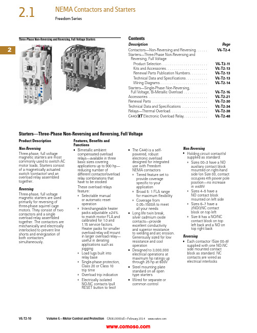
2Three-Phase Non-Reversing and Reversing, Full Voltage StartersContentsDescription PageContactors—Non-Reversing and Reversing. . . . . .V5-T2-4Starters—Three-Phase Non-Reversing andReversing, Full VoltageProduct Selection . . . . . . . . . . . . . . . . . . . . . . .V5-T2-11Kits and Accessories. . . . . . . . . . . . . . . . . . . . .V5-T2-13Renewal Parts Publication Numbers. . . . . . . . .V5-T2-13Technical Data and Specifications. . . . . . . . . . .V5-T2-13Wiring Diagrams. . . . . . . . . . . . . . . . . . . . . . . .V5-T2-14Starters—Single-Phase Non-Reversing,Full Voltage, Bi-Metallic Overload . . . . . . . . . . . .V5-T2-15Accessories . . . . . . . . . . . . . . . . . . . . . . . . . . . . . .V5-T2-21Renewal Parts . . . . . . . . . . . . . . . . . . . . . . . . . . . .V5-T2-30Technical Data and Specifications . . . . . . . . . . . . .V5-T2-34Relays—Thermal Overload. . . . . . . . . . . . . . . . . . .V5-T2-38C440/XT Electronic Overload Relay. . . . . . . . . . . .V5-T2-48Starters—Three-Phase Non-Reversing and Reversing, Full VoltageProduct DescriptionNon-ReversingThree-phase, full voltagemagnetic starters are mostcommonly used to switch ACmotor loads. Starters consistof a magnetically actuatedswitch (contactor) and anoverload relay assembledtogether.ReversingThree-phase, full voltagemagnetic starters are usedprimarily for reversing ofthree-phase squirrel cagemotors. They consist of twocontactors and a singleoverload relay assembledtogether. The contactors aremechanically and electricallyinterlocked to prevent lineshorts and energization ofboth contactorssimultaneously.Features, Benefits andFunctions●Bimetallic ambientcompensated overloadrelays—available in threebasic sizes coveringapplications up to 900 hp—reducing number ofdifferent contactor/overloadrelay combinations thathave to be stockedThese overload relaysfeature:●Selectable manualor automatic resetoperation●Interchangeable heaterpacks adjustable ±24%to match motor FLA andcalibrated for 1.0 and1.15 service factors.Heater packs for smalleroverload relay will mountin larger overload relay—useful in deratingapplications such asjogging●Load lugs built intorelay base●Single-phase protection,Class 20 or Class 10trip time●Overload trip indication●Electrically isolatedNO-NC contacts (pullRESET button to test)●The C440 is a self-powered, robustelectronic overloaddesigned for integrateduse with FreedomNEMA contactors●Tiered feature set toprovide coveragespecific to yourapplication●Broad 5: 1 FLA rangefor maximum flexibility●Coverage from0.05–1500A to meetall your needs●Long life twin break,silver cadmium oxidecontacts—provideexcellent conductivityand superior resistanceto welding and arc erosion.Generously sized for lowresistance and cooloperation●Designed to 3,000,000electrical operations atmaximum hp ratings upthrough 25 hp at 600V●Steel mounting platestandard on all opentype starters●Wired for separate orcommon controlNon-Reversing●Holding circuit contact(s)supplied as standard:●Sizes 00–3 have a NOauxiliary contact blockmounted on right-handside (on Size 00, contactoccupies 4th power poleposition—no increasein width)●Sizes 4–5 have aNO contact blockmounted on left side●Sizes 6–7 have a2NO/2NC contactblock on top left●Size 8 has a NO/NCcontact block on topleft back and a NO ontop right backReversing●Each contactor (Size 00–8)supplied with one NO-NCside mounted contactblock as standard. NCcontacts are wired aselectrical interlocks2Freedom SeriesProduct SelectionWhen Ordering Supply ●Catalog number ●Heater pack number (see selection table, Pages V5-T2-40 to V5-T2-42) or full load currentT ype AN16/AN56 NEMA—Manual or Automatic Reset Overload Relay—Non-Reversing and Reversing 1Magnet Coils—AC or DC Starter coils listed in this section also have a 50 Hz rating as shown in the adjacent table. Selectrequired starter by catalog number and replace themagnet coil alpha designation in the catalog number (_) with the proper code suffix from the table.For Sizes 00–2 and 5–8, the magnet coil alpha designation will be the next to last digit of the listed catalog number.EXAMPLE: For a 380V, 50 Hz coil, change AN16BN0_C to AN16BN0L C. For all other sizes, the magnet coil alpha designation will be the last digit of the listed catalog number.For DC Magnet Coils , see Accessories, Pages V5-T2-28 and V5-T2-29.AC SuffixNotes1Starter catalog numbers do not include heater packs. Select one carton of three heater packs. Heater pack selection, Pages V5-T2-40 to V5-T2-42.2Maximum horsepower rating of starters for 380V 50 Hz applications:3Underscore (_) indicates coil suffix required, see AC Suffix table.4The service-limit current ratings represent the maximum rms current, in amperes, which the controller shall be permitted to carry for protracted periods in normal service. At service-limit current ratings, temperature rises shall be permitted to exceed those obtained by testing the controller at its continuous current rating. The current rating of overload relays or trip current of other motor protective devices used shall not exceed the service-limit current rating of the controller.5Common control. For separate 120V control, insert letter D in 7th position of listed catalog number. Example: AN56VN D 0CB.6NEMA Sizes 00 and 0 only.7NEMA Sizes 00 and 0 only. Sizes 1–8 are 24/60 only.NEMA Size Continuous Ampere Rating Service-Limit Current Rating (Amperes) 4Maximum UL Horsepower 2Three-PoleNon-Reversing 3Three-Pole Reversing 3Vertical Reversing 3Single-Phase Three-Phase 115V 230V 208V 240V 480V 600V Catalog Number Catalog Number Catalog Number 009111/311-1/21-1/222AN16AN0_C AN56AN0_C —01821123355AN16BN0_CAN56BN0_C AN56BNV0_12732237-1/27-1/21010AN16DN0_B AN56DN0_B AN56DNV0_2455237-1/210152525AN16GN0_B AN56GN0_B AN56GNV0_390104——25305050AN16KN0_AN56KN0_AN56KNV0_4135156——4050100100AN16NN0_AN56NN0_AN56NNV0_5270311——75100200200AN16SN0_B AN56SN0_B —6540621——150200400400AN16TN0_C AN56TN0_C —7810932——200300600600AN16UN0_B AN56UN0_B —8 512151400——400450900900AN16VN0_BAN56VN0_B—Size 0Non-Reversing StarterSize 1Reversing StarterCoil Volts and Hertz Code Suffix Coil Volts and Hertz Code Suffix 120/60 or 110/50A 380–415/50L 240/60 or 220/50B 550/50N 480/60 or 440/50C 24/60, 24/50 7T 600/60 or 550/50D 24/50U 208/60E 32/50V 277/60H 48/60W 208–240/60 6J 48/50Y 240/50K48/50YNEMA Size 00012345678Horsepower1-1/25102550751503006009002Two-Speed Selective ControlWhen Ordering Supply●Catalog number plusmagnet coil code suffix.Example: Size 0—AN700BN022B●Heater pack number or fullload current for each speedFor two-speed other thanselective control:●Catalog number plusmagnet coil code suffix andoption required. Example:AN700BN022B exceptcompelling●Heater pack number or fullload current for each speedNote: Two-speed startersare designed for starting andcontrolling both separate(two-winding) and reconnectable(one-winding) motors. Separatewinding, WYE-WYE motorshave a separate winding foreach speed. Reconnectable,consequent pole motors use thesame winding for both speeds. Allstandard starters are wiredfor selective control.Separate Winding 1Reconnectable Winding 1Magnetic Coils—AC or DCNotes1 If branch circuit protective device is 45A or greater, C320FBR1 fuse kit(s) may be required for circuit protection per NEC 530-072.2 NEMA Sizes 00 and 0 only. Sizes 1–5 are 24/60 only.Maximum Horsepower—60/50 HertzNEMASizeOpen TypeCatalog Number Constant or Variable Torque Constant Horsepower115V200V230V460V/575V115V200V230V460/575V1-1/233512230AN700BN022_37-1/27-1/2102557-1/21AN700DN022_—101525—7-1/210202AN700GN022_—253050—2025403AN700KN022_—4050100—3040754AN700NN022_—75100200—60751505AN700SN022_Prices of starters do not include heater packs. Select two packs (two overload relays, one for each speed). Heater pack selection, Pages V5-T2-40 to V5-T2-42.Maximum Horsepower—60/50 HertzNEMASizeOpen TypeConstant or Variable Torque Constant HorsepowerConstant orVariable TorqueConstantHorsepower 115V200V230V460V/575V115V200V230V460/575V Catalog Number Catalog Number1-1/233512230AN700BN0218_AN700BN0219_37-1/27-1/2102557-1/21AN700DN0218_AN700DN0219_—101525—7-1/210202AN700GN0218_AN700GN0219_—253050—2025403AN700KN0218_AN700KN0219_—4050100—3040754AN700NN0218_AN700NN0219_Prices of starters do not include heater packs. Select two packs (two overload relays, one for each speed). Heater pack selection, Pages V5-T2-40 to V5-T2-42.Coil Voltage and Hz Code Suffix Coil Voltage and Hz Code Suffix Coil Voltage and Hz Code Suffix120/60 or 110/50A277/60H24/60, 24/50 2T240/60 or 220/50B208–240/60J24/50U480/60 or 440/50C240/50K32/50V600/60 or 550/50D380–415/50L48/60W208/60E550/50N48/50YTwo-WindingAN700DN022One-WindingAN700BN0218One-WindingAN700DN02182Freedom SeriesKits and Accessories●Auxiliary contacts, contactor mounted—Pages V5-T2-25 to V5-T2-27●Transient suppressor, for magnet coil—Page V5-T2-24●Timers—solid-state and pneumatic, mount on contactor—Page V5-T2-22Renewal PartsPublication Numbers●See Page V5-T2-30Technical Data and SpecificationsWire (75°C) Sizes—AWG or kcmil—NEMA Sizes 00–2—Open and EnclosedWire (75°C) Sizes—AWG or kcmil—NEMA Sizes 3–8—Open and EnclosedPlugging and Jogging Service Horsepower Ratings 3Notes1Minimum per NEC. Maximum wire size: Sizes 00 and 0 to 8 AWG and Sizes 1–2 to 2 AWG.2Two compartment box lug.3Maximum horsepower where operation is interrupted more than 5 times per minute, or more than 10 times in a 10 minute period. NEMA Standard ICS2-1993 table 2-4-3.NEMA SizeWire Size 1 Cu OnlyPower T erminals—Line 0012–16 AWG stranded, 12–14 AWG solid 08–16 AWG stranded, 10–14 AWG solid 18–14 AWG stranded or solid23–14 AWG (upper) and/or 6–14 AWG (lower) stranded or solid 2Power T erminals—Load—Cu Only (stranded or solid)00–014–6 AWG stranded or solid 1–214–2 AWG stranded or solidControl T erminals—Cu Only 12–16 AWG stranded, 12–14 AWG solidNEMA SizeWire Size 2Power T erminals—Line and Load 31/0–14 AWG Cu/Al4Open—3/0–8 AWG Cu; Enclosed—250 kcmil—6 AWG Cu/Al 5750 kcmil—2 AWG; or (2) 250 kcmil—3/0 AWG Cu/Al 6(2) 750 kcmil—3/0 AWG Cu/Al 7(3) 750 kcmil—3/0 AWG Cu/Al 8(4) 750 kcmil—1/0 AWG Cu/AlControl T erminals—Cu Only 12–16 AWG stranded, 12–14 AWG solidNEMA Size 200V 230V 460V 575V 00—1/21/21/201-1/21-1/2221335527-1/21015153152030304253060605607515015061251503003002Wiring DiagramsThree-Phase and Single-Phase Applications。
江苏安科瑞电器制造有限公司 Acrel-6000 B3 型电气火灾监控设备 安装使用说明书

345Acrel-6000/B3型电气火灾监控设备安装使用说明书V1.1江苏安科瑞电器制造有限公司危险和警告本设备只能由专业人士进行安装和维护,对于因不遵守本手册说明进行的违规操作所引起的故障,厂家将不承担任何责任。
触电、燃烧或爆炸的危险⏹设备只能由取得资格的工作人员才能进行安装和维护。
⏹对设备进行维护操作前,应隔离电源供应。
⏹要用一个合适的电压检测设备来确认电压已切断。
⏹在将设备通电前,应将所有的部件恢复原位。
⏹设备在使用中应提供正确的额定电压。
不注意这些预防措施可能会引起严重伤害。
申明:版权所有,未经本公司之书面许可,此手册中任何段落,章节内容均不得被摘抄、拷贝或以任何形式复制、传播,否则一切后果由违者自负。
本公司保留一切法律权利。
本公司保留对本手册所描述之产品规格进行修改的权利,恕不另行通知。
订货前,请垂询当地代理商以获悉本产品的最新信息。
目录1.概述 (2)2.基本功能 (2)2.1.监控报警功能 (2)2.2.控制输出功能 (2)2.3.故障报警功能 (2)2.4.自检功能 (2)2.5.报警记录存储查询功能 (2)2.6.电源功能 (2)2.7.远程控制功能 (3)2.8.权限控制功能 (3)3.主要技术参数 (3)3.1.电源 (3)3.2.工作制 (3)3.3.通讯方式 (3)3.4.监控容量 (3)3.5.监控报警项目 (3)3.6.故障报警项目 (3)3.7.控制输出 (3)3.8.自检项目 (3)3.9.事件记录 (4)3.10.操作分级 (4)3.11.使用环境条件 (4)4.设备组成部件 (4)4.1.主要参数及组成部件 (4)4.2.面板元件布置及功能说明 (4)5.安装与调试 (5)5.1.系统示意图 (5)5.2.设备安装 (5)5.2.1.环境 (5)5.2.2.安装方式 (5)5.2.3.设备尺寸 (5)5.3.接线 (6)5.4.单机调试 (6)5.5.系统调试 (7)6.使用说明 (8)6.1设备启动与登录 (8)6.2“隐患”页面操作 (10)6.3“状态”页面操作 (11)6.4“列表”页面操作 (12)6.5“事件”页面操作 (13)6.6“自检”页面操作 (14)6.7“维护”页面操作 (15)7.用户须知 (16)注意:本说明书针对Acrel-6000/B3型电气火灾监控设备及系统软件的使用进行全面介绍,用户使用前应仔细阅读,充分理解设备及系统软件的各项功能,以便正确、规范操作。
- 1、下载文档前请自行甄别文档内容的完整性,平台不提供额外的编辑、内容补充、找答案等附加服务。
- 2、"仅部分预览"的文档,不可在线预览部分如存在完整性等问题,可反馈申请退款(可完整预览的文档不适用该条件!)。
- 3、如文档侵犯您的权益,请联系客服反馈,我们会尽快为您处理(人工客服工作时间:9:00-18:30)。
搅拌机:380V/1.5Kw 一台
搅拌机控制方式:自动/手动
自动时与电极液位连锁启动/关闭,高液位启动,低液位停止。
PH探头:用于测量水的PH值,并控制加碱泵的加药量。
电极液位:设一高液位和一低液位。
3.3
气动隔膜泵用于将水提升进入沉淀池,一用一备。最大用气量:2立方米每分钟。
一键松板:在 灯灭掉的情况下,点击“一键松板”按钮,压滤机拉开,便于更换滤布。
一键压紧:在更换完滤布后,点击“一键压紧”按钮,压滤机重新压紧。
4、
这些是控制压滤机工作的一些信号。污泥池即污泥浓缩池;压滤机液位即压滤机接液槽液位;
当这些信号灯亮起时,表示达到该信号条件。
5、
这些旋钮为调试旋钮,只有在输入密码后才可控制。
排泥阀、加碱泵、PAC/PAM加药泵都点击自动;
PAC/PAM溶药搅拌机,当配制药剂时点击手动,药剂配制完毕点击自动;
点击图1中的 图标后进入如下图3界面:
图3
首先要设置各个参数(设置前也需要输入密码 ):
1、
该图内的参数无法设置,该图是显示参数。
2、
压板次数设置:压泥的板数,卸一板泥为压一板。
压泥时间设置:压滤泵的单次工作上限时间,如果到达该时间,则压滤泵停止工作,压滤机开始自动拉板卸泥。
药箱:200L
加药泵:380V/0.25Kw 一台
控制方式:自动/手动
自动时与调节池气动隔膜泵连锁启动/关闭
搅拌机:380V/0.55Kw
控制方式:自动/手动
配制药剂时手动开启,自动时:搅拌机马上启动,延时2小时后关闭。
5
压滤机系统相关设备全部为原有旧设备。
包含:压滤机、污泥浓缩池、压滤泵、冷却泵、污泥浓缩池搅拌机等设备。
压滤机的控制为全自动:污泥浓缩池内污泥到达中液位后,开始压泥,当压滤机接液槽低液位检测不到水或者到达规定的时间后,开始拉板,拉板结束后,震打电机开始启动,泥饼随着震动掉入下面的接泥袋中,到达设定的震打次数后,压滤机开始压紧进入保压状态,等待下一次的压泥。
6
图1
点击“废水系统”图标进入如下图2操作界面:
1.2机械
a.请不要将工具、螺丝等放置在水泵等电器上,以免造成触电危险。
b.确认所有的管道都有足够的固定和支撑。在开启系统阀门后,仔细检查以保证所有阀门正常开闭。
1.3开停机
开机前先检查系统总的电源、水源是否正常开启,停机后再关闭系统总的电源、水源,其他操作必须遵守开停机程序来保证工作人员的安全。
1.4 通道
4.2 混凝剂
混凝剂加药系统附件:药箱、加药泵、搅拌机。
药箱:200L
加药泵:380V/0.25Kw 一台
控制方式:自动/手动
自动时与调节池气动隔膜泵连锁启动/关闭
搅拌机:380V/0.55Kw
控制方式:自动/手动
配制药剂时手动开启,自动时:搅拌机马上启动,延时2小时后关闭。
4.3 絮凝剂
絮凝剂加药系统附件:药箱、加药泵、搅拌机。
i.压力表:每十二个月要作校验。
j.各类水泵:每月要检查轴承润滑和机械密封是否泄漏。
k.搅拌机:每月要检查轴承润滑。
l.pH电极:每30天清洗探头并重新进行系统标定。
m.流量仪表:每十二个月检查校验。
注意:设备不能使用高压水冲洗。
4、
为2个PH值显示和加碱泵加碱PH设定,低于低点加碱泵开始运行,高于高点加碱泵停止运行。
5、
改变参数都必须输入密码。密码8个1
6、正常运行时:
集水坑提升泵A或者B点击自动,这2台泵为一用一备,不需同时开启;
调节池搅拌机点击自动;
调节池提升泵A或者B点击自动,这2台泵为一用一备,不需同时开启;
回用水泵点击自动;
图2
1、点击“集水坑提升泵A”下方的“手动”2个字则该泵启动;
点击“集水坑提升泵A”下方的“自动”2个字则该泵受PLC控制;
点击“集水坑提升泵A”下方的 图形则该泵停止;
2、
为各池液位显示,当到达该液位时, 会亮起。
3、
为排泥阀参数设定,如停止时间设定为200分钟,运行时间设定为10分钟,则表示排泥阀每关闭200分钟后开启10分钟再关闭。
点击图1中的 图标后进入如下图4界面:
图4
该图记录了详细的报警履历。
7
7
a.计量泵前或后2个单向阀堵塞,需拆卸清洗。
b.膜片破损,需更换膜片。
c.计量泵前级Y型过滤器堵塞,需拆卸清洗。
7
观察触摸屏上调节池上液位灯是否还亮着,如果亮着,则需要将调节池上液位拆下,然后用清水冲洗安装上液位的管道。因为有气泡附着在液位电极上,导致电极导通,使灯常亮。
3处理设备构筑物的运行与控制参数
3.1
地坑用于收集地沟中的水。
附件:PH探头、地坑泵、电缆浮球液位。
PH探头:用于测量地坑水的PH值。
地坑泵:380V/0.75Kw 一用一备
控制方式:自动/手动
自动时与电缆浮球液位连锁启动/关闭,高液位启动,低液位停止。
电缆浮球液位:设一高液位和一低液位。
3.2
调节池用于收集和混合各种废水,并调节PH值。
控制方式:自动/手动
自动时与调节池搅拌机连锁启动/关闭,搅拌机启动后泵延时1分钟(时间可调)启动,搅拌机停止后泵停止。
3.4
气动隔膜泵后的管道中加入了2个DN80的管道混合器,用于混合所加入的药剂。
3.5
沉淀池用于分离水和泥,清水从上端溢流堰流入回用水池,泥从下部管道排入污泥浓缩池。
附件:气动排泥阀
控制方式:自动/手动
自动时:调节池气动隔膜泵累计运行A分钟后,排泥阀自动开启B分钟,A/B时间可调。污泥浓缩池高液位,终止排泥。
3.6
回用水池用于收集沉淀池的清水。
附件:回用水泵、电缆浮球液位。
回用水泵:380V/2.2Kw 一台
控制方式:自动/手动
自动时气维修人员不得擅自维修电气设备。
c.系统启动前检查气源、水源、电源是否开启。
d.开启、关闭阀门时应缓慢进行,到设定点为准。不可猛力冲击操作。
e.对设备应定期进行检修。
f.总电源或水泵接线更换之后,重新检查各水泵的运转方向。
g.设备运行时应对水质做好记录,通常每4小时记录一次。
h.报警后一定要及时消音,观察报警内容并及时处理。
电缆浮球液位:设一高液位和一低液位。
3.
除油过滤器用于除去回用水中的油污。根据进水口和出水口的压力表读数之间的差值清洗滤袋,压差超过0.15MPa时需清洗或者更换。
4
4.1
加碱系统附件:药箱、加碱泵。
药箱:200L
加碱泵:380V/0.25Kw 一台
控制方式:自动/手动
自动时由pH控制器控制,pH值低点启动,pH值高点关闭。
在系统周围应有足够的通道和照明,以便操作和维护的安全。
1.5 安全用具
当操作人员在进行接触化学药品的工作时,须戴手套和护目镜。
1.6 安全检查表
a将所有紧急电话、化学品伤害应急处理措施贴在明显位置。
b.保证所有操作人员熟悉与该设备相关的安全事项。
c.熟悉所有泵和阀门的关闭位置。
d.确保设备周围通道畅通和足够的照明。
振打次数设置:设定振打电机振打卸泥的次数。
压滤机无液延时设置:压滤机接液槽低液位信号延时检测的时间,如设置为10秒,则信号则在压滤泵启动后10秒开始检测,检测到无水时,则认为压滤机内泥已满自动开始进入卸泥步骤。
3、
压滤系统自动:设定好参数后点击此按钮,压滤机系统开始自动工作,该按钮亮起。当压泥板数到达设定的 次数后,压滤机停止工作,该按钮灭灯。
1 人身安全注意事项
1.1电气
系统内使用了三相电源,有可能对人体造成危险。
系统在工作时需要非常小心。
a.定期检查接线端子是否接触良好。
b.如发现有损坏的电气元件,在修复或更换前要先隔离该元件。
c.检查电器箱密封是否良好以防进水。
d.只允许有资格的电气技术人员进行检修工作。
e.三相电动机处于工作状态时不可切断水泵上的电源线。
7
a.检查该水池上和下液位是否卡住。
b.检查固定液位的扎带是否断裂,导致下液位下落到比泵吸水水位还低的位置。
c.水池液位均为电缆浮球液位,直接拉起即可,简单易操作。
7
a.增加PAC和PAM加药量。
b.减低气动隔膜泵供气压力,使管道水流减少,增加澄清时间。
7
更换或清洗过滤器中的滤袋。
8
a.操作前必须仔细阅读本操作手册。
e.保持设备洁净。
f.在需要处提供足够的通风。
g.具备化学品防护用具。
2
地坑中的废水由地坑泵提升进入调节池,生产车间的废水也进入调节池,调节池内投加碱(由PH控制器自动控制),然后调节池内废水通过气动隔膜泵进入沉淀池,在进入沉淀池的管道中有管道混合器,分别加入混凝剂和絮凝剂。
经过沉淀后的清水进入回用水池,然后通过回用水泵加压,经过除油过滤器过滤后进入回用管道。