HSMBJ5949B中文资料
SAE J 594中文版

SAE J594 回复反射器中文译本-2018年6月版本文件进行了修订,以更新各种参考资料并修复小的印刷错误。
此外,删除了第7.1节“光度设计指南”,因为它不是必需的。
此外,图2的光度要求将1.5度观察角的(0,0)入射角值从6更改为7。
根据以往的历史,当原始光度表被更改为添加每入射勒克斯的最小毫坎德拉要求,以使用国际单位标准化文件时,该值被四舍五入而非四舍五舍五入。
与使用乘数转换单位的其他最小值的计算相比,这使得该特定值不正确。
这一变化很小,但应予以注意。
SI单位和英制单位之间的换算计算现已作为注释包含在内。
此外,还增加了投影仪光源CCT(相关色温)的公差,到目前为止还不存在。
此外,还添加了图1A和1B,以帮助演示测量的入射角与观察角的概念。
添加图1C是为了描述一种可接受的方法,该方法通过使用校准投影仪光源和使用分光辐射计的光纤布置来测量测试项目的反射颜色。
1.范围本SAE标准提供了回复反射器的试验程序、要求和指南。
2.参考文献2.1适用文件以下出版物在本文规定的范围内构成本规范的一部分。
除非另有说明,否则应使用SAE出版物的最新版本。
2.1.1SAE出版物可从SAEInternational购买SAEJ575总宽小于2032mm的车辆上使用的照明装置和部件的试验方法和设备SAEJ576塑料材料或机动车透镜和反射镜等光学零件用材料照明设备SAEJ578颜色规格SAEJ759照明识别代码2.2相关出版物以下出版物仅供参考,并非SAE技术报告的必要组成部分。
2.2.1SAE出版物可从SAEInternational购买SAEJ585总宽小于2032mm的机动车用尾灯(后位灯)总宽小于2032mm的机动车用SAEJ586制动灯总宽小于2032mm的机动车用SAEJ588转向信号灯总宽小于2032mm的道路车辆用SAEJ592示宽灯SAEJ2040总宽大于等于2032mm的车辆用尾灯(后位灯)总宽大于等于2032mm的车辆用SAEJ2041回复反射器SAEJ20422032mm或以上机动车用示廓灯、侧标志灯和识别灯宽度SAEJ22612032mm或以上机动车用刹车灯和前后转向信号灯总宽度SAEJ2442道路车辆车外灯和回复反射装置安装的协调规定摩托车除外2.2.2联邦出版物可从美国政府印刷办公室文件总监处获得联邦机动车安全标准标题49,CFR571.1083.定义3.1反射反射器车辆上使用的装置,通过接近车辆前照灯的反射光向接近的驾驶员显示存在。
ABB JOKAB SAFETY 产品说明书.pdf_1701680643.2574954

Original instructionsSmileEmergency stop with indicationRead and understand this documentPlease read and understand this document before using the products. Please consult your ABB JOKAB SAFETY representative if you have any questions or comments.WARRANTYABB JOKAB SAFETY’s exclusive warranty is that the products are free from defects in materials and workmanship for a period of one year (or other period if specified) from date of sale by ABB JOKAB SAFETY.ABB JOKAB SAFETY MAKES NO WARRANTY OR REPRESENTATION, EXPRESSED OR IMPLIED, REGARDING NON-INFRINGEMENT, MERCHANTABILITY, OR FITNESS FOR PARTICULAR PURPOSE OF THE PRODUCTS, ANY BUYER OR USER ACKNOWLEDGES THAT THE BUYER OR USER ALONE HAS DETERMINED THAT THE PRODUCTS WILL SUITABLY MEET THE REQUIREMENTS OR THEIR INTENDED USE. ABB JOKAB SAFETY DISCLAIMS ALL OTHER WARRANTIES, EXPRESSED OR IMPLIED. LIMITATIONS OF LIABILITYABB JOKAB SAFETY SHALL NOT BE RESPONSIBLE FOR SPECIAL, INDIRECT, OR CONSEQUENTIAL DAMAGES, LOSS OF PROFITS OR COMMERCIAL LOSS IN ANY WAY CONNECTED WITH THE PRODUCTS, WHETHER SUCH CLAIM IS BASED ON CONTRACT, WARRANTY, NEGLIGENCE, OR STRICT LIABILITY.In no event shall responsibility of ABB JOKAB SAFETY for any act exceed the individual price of the product on which liability asserted.IN NO EVENT SHALL ABB JOKAB SAFETY BE RESPONSIBLE FOR WARRANTY, REPAIR, OR OTHER CLAIMS REGARDING THE PRODUCTS UNLESS ABB JOKAB SAFETY’S ANALYSIS CONFIRMS THAT THE PRODUCTS WERE PROPERLY HANDLED, STORED, INSTALLED, AND MAINTAINED AND NOT SUBJECT TO ABUSE, MISUSE, OR INAPPROPRIATE MODIFICATION OR REPAIR.SUITABILITY FOR USEABB JOKAB SAFETY shall not be responsible for conformity with any standards, codes, or regulations that apply to the combination of products in the customer’s application or use of the product. At the customer’s request, ABB JOKAB SAFETY will provide applicable third party certification documents identifying ratings and limitations of use that apply to the products. This information by itself is not sufficient for a complete determination of the suitability of the products in combination with the end product, machine, system, or other application or use.The following are some examples of applications for which particular attention must be given. This is not intended to be an exhaustive list of all possible uses of the products, nor is it intended to imply that the uses listed may be suitable for the products:Outdoor use, uses involving potential chemical contamination or electrical interference, or conditions or uses not described in this document.Nuclear energy control systems, combustion systems, railroad systems, aviation systems, medical equipment, amusement machines, vehicles, and installations subject to separate industry or government regulations. Systems, machines, and equipment that could present a risk to life or property.Please know and observe all prohibitions of use applicable to the products.NEVER USE THE PRODUCTS FOR AN APPLICATION INVOLVING SERIOUS RISK TO LIFE OR PROPERTY WITHOUT ENSURING THAT THE SYSTEM AS A WHOLE HAS BEEN DESIGNED TO ADDRESS THE RISKS, AND THAT THE ABB JOKAB SAFETY PRODUCT IS PROPERLY RATED AND INSTALLED FOR THE INTENDED USE WITHIN THE OVERALL EQUIPMENT OR SYSTEM.PERFORMANCE DATAWhile every effort has been taken to ensure the accuracy of the information contained in this manual ABB JOKAB SAFETY cannot accept responsibility for errors or omissions and reserves the right to make changes and improvements without notice. Performance data given in this document is provided as a guide for the user in determining suitability and does not constitute a warranty. It may represent the result of ABB JOKAB SAFETY’S test conditions, and the users must correlate it to actual application requirements. Actual performance is subject to the ABB JOKAB SAFETY Warranty and Limitations of Liability.Table of Contents1Introduction (4)Scope (4)Audience (4)Prerequisites (4)Special notes (4)2Overview (5)General description (5)Safety regulations (5)3Connections (6)Connection examples (7)4Installation and maintenance (11)Installation precautions (11)Maintenance (11)5Operation (12)LED indication (12)6Model overview (13)Accessories (13)7Technical data (14)Dimensions (15)8EC Declaration of conformity (16)1 IntroductionScopeThe purpose of these instructions is to describe the emergency stop Smile and to provide the necessary information required for installation and operation.AudienceThis document is intended for authorized installation personnel.PrerequisitesIt is assumed that the reader of this document has knowledge of the following:•Basic knowledge of ABB Jokab Safety products.•Knowledge of machine safety.Special notesPay attention to the following special notes in the document:Warning!Danger of severe personal injury!An instruction or procedure which, if not carried out correctly, may result in injury to the technician or other personnel.Caution!Danger of damage to the equipment!An instruction or procedure which, if not carried out correctly, may damage the equipment.NB: Notes are used to provide important or explanatory information.2 OverviewGeneral descriptionIn order to fulfil the need for a small and easy to install E-stop, Smile has been developed. The size of the device makes it possible to be installed wherever needed. With M12 connections or cable and centralized mounting holes. Smile is very easy to install, especially on aluminium extrusions. There are different versions available, either with one or two M12 connections or cable. Two M12 connectors are used to enable the connection of E-stops in series. On the top of the Smile E-stop unit, an LED indicates the status.Warning! The emergency stop Smile normally needs to be complemented with other safety functions such as interlocking guards etc. Refer to risk analysis.NB: The emergency stop shall not be used as normal stop of the machine, only in case of emergency.Safety regulationsWarning!Carefully read through this entire manual before using the device.The devices shall be installed by a trained electrician following the Safety regulations, standards and the Machine directive.Failure to comply with instructions, operation that is not in accordance with the use prescribed in these instructions, improper installation or handling of the device can affect the safety of people and the plant.For installation and prescribed use of the product, the special notes in the instructions must be carefully observed and the technical standards relevant to the application must be considered.In case of failure to comply with the instructions or standards, especially when tampering with and/or modifying the product, any liability is excluded.3 ConnectionsElectrical connections - SmileNB: Smile 10EA/11EA/12EA can be used with any safety PLC or safety relay, but if LED indication is required the voltage over pin-1 (+) and pin-3 (-) must be between 19.2 – 28.8 VDC.Caution!When connected to an ABB Jokab Safety safety relay (such as an RT6 or RT9) and voltage (+) is supplied from the output S13, a maximum of three Smile units may be connected in series. This must be done with caution (especially in warm environments) as this affects the heat generation within the safety relay.If more than three units are connected in series, voltage (+) should be supplied from another source (e.g. A1).M12 5-pole male seen from cablesideM12 5-pole female seen from cablesideSmile 10EA 5-pole wired1 )Brown: Input 12 )White: Input 23 )Blue: 0 VDC 14 )Black: Output 25 )Grey:Output 1Smile 10EK 4x wires 1 )Input 1 2 )Input 2 3 )Output 2 4 )Output 1Smile 12EAInputM12 5-pole male1 )Input 12 )Input 23 )0 VDC 14 )Output 2, feedback5 )Output 1, feedbackOutputM12 5-pole female1 )Output 12 )Output 23 )0 VDC4 )Input 2, feedback5 )Input 1, feedback12345Smile 10EA12345Smile 11EA1234512345Smile 12EA1234Smile10EKSmile 11EAM12 5-pole male1 )Input 12 )Input 23 )0 VDC 14 )Output 25 )Output 11. To be connected only if LED indication is required.Connection examplesConnection example – Smile 10EASmile 10EA can be connected to either Pluto or a safety relay. The connection cable exits from underneath the unit.Single channel example with LED indication. Safety category 1Two channel example with LED indication. Safety circuit category 4+24V 0V I0Safety PLCPluto+24VIQ 10A-pulse0V I0I1Safety PLCPlutoSmile 11EA can be connected to either Pluto or a safety relay. Connection via M12 connector. Single channel example with LED indication. Safety category 1Two channel example with LED indication. Safety circuit category 4+24V 0V I0Safety PLCPluto+24VIQ 10A-pulse0V I0I1Safety PLCPlutoSmile 12EA can be connected to either Pluto or a safety relay. Single channel example with LED indication.Safety category 1. Connection via M12 connector + termination connector.Two channel example with LED indication.Safety circuit category 4. Connection via M12 connector + termination connector.Two channel serial connection example with LED indication.Safety circuit category 3. Connection via M12 connector + termination connector. Note that there is no termination connector for the Smile 12EA (C), this unit is being connected back to the Pluto/safety relay via a separate cable.+24V 0V I0Safety PLCPluto+24VIQ 10A-pulse0V I0I1Safety PLCPlutoSafety PLCPluto+24VIQ 10A-pulse0V I0I1Connection example – Smile 11EA & -12EABoth Smile 11EA and -12EA can be connected to either Pluto or a safety relay. Two channel example with LED indication.Safety category 3. Connection via M12 connectors. Note that there is no termination connector as the Smile 11EA (C) completes the circuit without the need for a termination connector (JST2) or return cable.LED indication exampleThe table shows the LED indication status of the emergency stop actuators from the connection example above.Emergency stop actuator statusLED indicationA B C A B C Released Released Released ‹---› Green Green Green Released Released Pressed ‹---› Green Green Red Released Pressed Released ‹---› Green Red OFF Released Pressed Pressed ‹---› Green Red OFF Pressed Released Released ‹---› Red OFF OFF Pressed Released Pressed ‹---› Red OFF OFF Pressed Pressed Released ‹---› Red OFF OFF PressedPressedPressed‹---›RedOFFOFFNB: More information about the LED indication can be found in chapter Operation .Safety PLCPluto+24VIQ 10A-pulse0V I0I14 Installation and maintenanceInstallation precautionsFirst mount Smile to the surface with two M5 bolts, and then attach the M12 connection(s).Warning! All the safety functions must be tested before starting up the system.MaintenanceWarning!The safety functions and the mechanics shall be tested regularly, at least once every year to confirm that all the safety functions are working properly (EN 62061:2005).In case of breakdown or damage to the product, contact the nearest ABB Jokab Safety Service Office or reseller. Do not try to repair the product yourself since it may accidentally cause permanent damage to the product, impairing the safety of the device which in turn could lead to serious injury to personnel.5 OperationWarning! The maximum number of operations (cycles) for the emergency stop Smile is 6050 operations. LED indicationLED Indication DescriptionLED on button GreenSafety device OK. Safety circuit closed.OFF Safety circuit interrupted (when an emergency stop actuator is pressed down, all following units in the safety circuit lose the LED function).Red Safety device actuator pressed down. Safety circuit interrupted.6 Model overviewType Article number DescriptionSmile 11EA 2TLA030051R0000 Emergency stop, red button, M12 5-pole maleSmile 11EAR 2TLA030051R0100 Emergency stop, red button, M12 5-pole male, reversedSmile 12EA 2TLA030051R0200 Emergency stop, red button, M12 5-pole male, M12 5-pole female Smile 10EA 2TLA030051R0400 Emergency stop, red button, 1 m cable (5-pole)Smile 10EK 2TLA030051R0600 Emergency stop, red button, short leads (4x wires, no LED connection) Smile 11SA 2TLA030051R0900 Safety stop, black button, M12 5-pole maleSmile 12SA 2TLA030051R1000 Safety stop, black button, M12 5-pole male, M12 5-pole female Smile 11SAR2TLA030051R1100Safety stop, black button, M12 5-pole male, reversedAccessoriesType Article number DescriptionJST22TLA030051R1300 Termination for Smile 12Emergency stop sign 2TLA030054R0700 Ø32.5 mm, Swedish, Danish, Finnish. For reversed Smile. Emergency stop sign2TLA030054R0800Ø32.5 mm, English, French, German. For reversed Smile.Smile 11EA Smile 10EA Smile 11EARSmile 10EKSmile 12EA JST2Termination for Smile 12Article number:2TLA030051R1300Emergency stop sign For reversed SmileArticle number:S, DK, FIN: 2TLA030054R0700 EN, F, D: 2TLA030054R08007 Technical dataManufacturerAddress ABB JOKAB SAFETYVarlabergsvägen 11SE-434 39 KungsbackaSwedenPower supplyOperating voltage (LED) 17-27 VDC ±10 %Current consumption (LED) 15 mAMinimum current (switches) 10 mA 10 VDC/10 VACMaximum current (switches) 2 A 24 VDCGeneralProtection class IP65Ambient temperature Storage: -30…+70°COperation: -10…+55°CHousing material Polyamide PA66, Macromelt, polybutylenterephthalate PBT, Polypropene PP, UL 94 V0 Contact material Silver alloy, gold platedConnectors Smile 10EA: 5-pole cable, 1 mSmile 10EK: 4x wiresSmile 11x*: M12 5-pole maleSmile 12x*: M12 5-pole male, M12 5-pole female* - x can be all models -EA, -EAR, -SA, -SARSize 84 x 40 x 52 (L x W x H) – see drawingWeight ~ 65 gColour Yellow base, red or black buttonActuator force (E-stop button) 22 ± 4NActuator travel ~ 4 mm to latchMechanical life > 50,000 operationsImpact resistance (half sinusoidal) Max. 150 m/s2, pulse width 11 ms, 3-axis (as per EN IEC 60068-2-27)Vibration resistance (half sinusoidal) Max. 50m/s2 at 10 Hz, 10 cycles, 3-axis (as per EN IEC 60068-2-6)Climate resistanceDamp heat, cyclical 96 hours, +25°C / 97%, +55°C / 93% relative humidity, as per EN IEC 60068-2-30 Damp heat, sustained 56 days, +40°C / 93% relative humidity, as per EN IEC 60068-2-78Dry heat 96 hours, +70°C, as per EN IEC 60068-2-2Cooling 96 hours, -40°C, as per EN IEC 60068-2-1Salt mist 96 hours, +35°C in a chemical solution with NaCl as per EN IEC 60068-2-11Safety-related characteristic data and ConformityConformity European Machinery Directive 2006/42/ECEN ISO 12100:2010, EN ISO 13849-1:2008, EN 62061:2005,EN 60204-1:2006+A1:2009, IEC 60664-1:2007, EN 61000-6-2:2005,EN 61000-6-4:2007, EN 60947-5-5:2005, EN ISO 13850:2006EN ISO 13849-1 Up to PL e, cat. 4 depending on system architectureCertificates InspectaSafety dataMechanical reliability B10d Emergency stop: Fault exclusion, up to 6050 operationsNB: A safety function with an emergency stop Smile can achieve Cat. 4/PL e according to EN 954-1/EN ISO 13849-1 only when a single Smile unit is connected to the control unit (safety-PLC or safety relay) in a dual channel configuration.DimensionsDimensions – SmileNB: All measurements in millimetres.8 EC Declaration of conformityABB JOKAB SAFETY Varlabergsvägen 11, SE-434 39 Kungsbacka, Sweden/jokabsafety。
HEF4049BT中文资料

Min Typ Max
3
-
15
0
-
VDD
−40 -
+85
-
-
3.75
-
-
0.5
-
-
0.08
Unit V V °C ns/V ns/V ns/V
HEF4049B_5
Product data sheet
Rev. 05 — 11 November 2008
© NXP B.V. 2008. All rights reserved.
6. Pinning information
6.1 Pinning
Fig 4. Pin configuration
HEF4049B
VDD 1 1Y 2 1A 3 2Y 4 2A 5 3Y 6 3A 7
VSS 8
16 n.c. 15 6Y 14 6A 13 n.c. 12 5Y 11 5A 10 4Y 9 4A 001aae602
HEF4049BT
SO16
plastic small outline package; 16 leads; body width 3.9 mm
JED-593清洁度要求

JED-593 : 2006-11 Page 2WABCO Specification3 Cleanliness classes3.1 DefinitionThe permissible level of residual contamination and the permissible types of particles are defined according to the function of the part.Several classification methods are used to define the permissible limits of residual contamination. Due to the high quality requirements for WABCO devices, WABCO uses the particle size distribution method.In general, the devices or parts shall not contain any solid particles (e.g. metal particles, plastic par-ticles, elastomer particles) having a longest dimension > 1 mm.3.1.1 Particle size classesISO 16232 and VDA 19 classify the particles according to their largest dimension.Particle sizeclass Size [µm] B 5 ≤ x < 15 C 15 ≤ x < 25 D 25 ≤ x < 50 E 50 ≤ x < 100 F 100 ≤ x < 150 G 150 ≤ x < 200 H 200 ≤ x < 400 I 400 ≤ x < 600 J 600 ≤ x < 1000 K1000 ≤ xWABCO uses this classification. The smallest particle size classes B and C, indicating values below 25 µm, are currently not being used at WABCO because no functional impairment has so far been reported in these cases.3.1.2 Cleanliness levelsISO 16232 and VDA19 define cleanliness levels which allow the logarithmic indication of the number of particles per particle size class. The number is related to a standardized area of 1000 cm² or, for liquids, to a standardized volume of 100 cm³.In devices, the only area considered is the functional surface area, for instance, the passage area of compressed air. The functional surface area is that part of the device’s surface which is decisive for the function of the device. It is precisely specified in the Inspection Specification, Doc. Code 636. If the area is smaller or greater than 1000 cm², an appropriate conversion has to be made.JED-593 : 2006-11 Page 3WABCO SpecificationNumber of particles per 1000cm² or 100cm³ Cleanliness levelMore than up to and including00 0 0 0 0 1 1 1 2 2 2 4 3 4 8 4 8 16 5 16 32 6 32 64 7 64 130 8130 250 9 250 500 10 500 1x10³ 11 1x10³ 2 x10³ 12 2 x10³ 4 x10³ 13 4 x10³ 8 x10³ 14 8 x10³ 16 x10³ 15 16 x10³ 32 x10³ 16 32 x10³ 64 x10³ 17 64 x10³ 130 x10³ 18 130 x10³ 250 x10³ 19 250 x10³ 500 x10³ 20 500 x10³ 1x10⁶ 21 1 x10⁶ 2 x10⁶ 22 2 x10⁶ 4 x10⁶ 23 4 x10⁶ 8 x10⁶ 248 x106 16 x1063.1.3 WABCO cleanliness classesWABCO defines cleanliness classes for devices and parts in order to have a clear allocation of par-ticle size classes to the relevant permissible cleanliness levels.The WABCO cleanliness class IV corresponds to the revision status B of JED-593.JED-593 : 2006-11 Page 4WABCO Specification3.2 Allocation of the WABCO cleanliness classes3.2.1Functional assessment of the device or partThe best method of allocating cleanliness classes is the functional assessment, taking into account• the function of the device or part and the evaluation of the effect of foreign particles on thefunction• the determination of the device/part areas to be included in the test, thus the actual surface • the media involved (e.g. oil, water, air).Only the careful analysis and assessment of the function can be the basis for the definition of meaningful cleanliness classes for devices or parts. In doing so, the individual residual contamina-tion limits have to be coordinated for parts working together.3.2.2 Determination of the actual conditionIf the device or part does not provide any indicators for the allocation of the cleanliness class, the allocation can be based on experience. For this purpose, the cleanliness class of the predecessor or a similar device or part is documented. The cleanliness class for the new device or part is derived from these data.Moreover, all the failures in the field and in the process which were due to contamination have to be taken into account.Please note: This approach requires the tolerances, the operational requirements and the func-tions of the device or part in question to be comparable!3.3 Documentation of the determined WABCO cleanliness classesThe documentation of the requirement is made in the Outline Drawing or Component Drawing by in-dication of JED-593, the cleanliness class and the functional surface area A F , see example. The functional surface area is the area for which the cleanliness requirement is specified. For the execu-tion of the analyses, this area must be described in an Inspection Specification, Doc. Code 636, or visualized by a sectional drawing included in the Inspection Specification document. In most cases, those areas which are subjected to normal ambient conditions in later operation will be excluded from the consideration.Example: JED-593 Class IV, A F = 450 cm²In certain cases, for instance components for electronic assemblies, the permissible degree of con-tamination has to be related to special material properties of the particles, such as c onductivity or hardness. In this case, this shall be made visible by special indication. Example: JED-593 Class X (conductive material), A F = 50 cm²JED-593 : 2006-11 Page 5WABCO Specification4 Determination of the technical cleanliness4.1 Extraction procedureBasically, the extraction is a cleaning process. The extraction method is selected in accordance with the properties of the device or part, such as geometry and material, and adhesion mechanisms of the particles on the device or part. Four parameter fields apply to the method.1. Cleaning medium2. Temperature3. Mechanical aspects4. Exposure timeDuring the extraction procedure care must be taken to prevent additional particles from detaching. It also has to be ensured that no particles are ingested by the equipment or cleaning medium, thus affecting the result of the analysis.The aim consists in washing off the unbound particles present on the functional surface area of the device or part, in order to collect these particles for analysis. The capability of this extraction proce-dure is proven once at the start in the form of a documented test.The qualification of the extraction conditions is assessed by repeated rinsing performed on the same inspection lot, on the basis of the decreasing behaviour. At the end of this process, the determinedcleanliness value shall be max. 10 % of the sum of all extraction steps.JED-593 : 2006-11 Page 6 Moreover, it shall be determined whether the function of the overall system is exposed to a risk dueto grease-bound particles. If this is the case, a grease-dissolving medium shall be used. Ethyl alco-hol is not suited for this purpose. A special cleaning medium shall be indicated in the Inspection Specification, Doc. Code 636.4.1.2 TemperatureThe extraction procedure is performed under normal laboratory conditions, i.e., with a normal room temperature prevailing and the cleaning medium having the same temperature. Any deviation from these conditions has to be specified in the Inspection Specification. It must be observed that such a deviation requires considerable work on the test equipment.4.1.3 Mechanical aspectsThe extraction procedure aims at detaching the dirt particles from the part. In the simplest form, this can be do by using a wash bottle. All functional areas have to be accessible to visual inspection.A more reproducible procedure is the pressure rinsing method using a defined pressure. The pres-sure of the jet of test liquid shall not detach any particles which in normal operation would firmly ad-here. Definitions going beyond the use of wash bottles shall be given in the Inspection Specification.The use of ultrasonic baths is permitted, but it requires the entire part to be immersed in the solvent.4.1.4 Exposure timeThe exposure time shall ensure that all the particles adhering to the surface are definitely detached.4.2 Analysis methodWABCO applies the particle size distribution analysis with microscopy, because the gravimetric analysis is not useful for large devices having particle quantities of less than 10 mg. Below this limit, the capability of weighing methods is normally insufficient, and external influences, such as humidity, affect the result of the analysis.4.2.1 FilteringIn case of considerable particle quantities or large quantities of grease, a filter cascade should be used. Normally, the use of a simple filter should be aimed at, because this facilitates the determina-tion of the distribution curve. In case of application of a filter cascade, the distribution shall be de-termined for each individual filter, and the results shall be summed up.The selection of the mesh size has to be based on the fact that the mesh has only two dimensions.It must be ensured that all relevant particles, i.e., also the oblong ones, are caught by the filter or the cascade. For WABCO, this means that the filters applied have a maximum mesh size of 5 µm.The filters used for the analysis with light-microscopic means shall provide the highest possible con-trast.4.2.2 Determination of the particle size distributionThe lower limit of the particles considered is defined to be 25 µm. On a microscope equipped with camera, the entire filter is read into an image processing program, and the number of particles per size class is counted. The size is the largest dimension in top view. In the evaluation, the repeatabil-ity of illumination, grey values and contrast has to be observed.The setting mode can be taken from the manufacturer’s description of the analysis system; it shallbe documented for the relevant evaluation.WABCO Specification。
SMBJ50CA中文资料

10
Tj = 25°C f = 1.0 MHz Vsig = 50 mV p-p
1
10
100
1000
VRWM, REVERSE STANDOFF VOLTAGE (V) Fig. 2 Typical Junction Capacitance
IP, PEAK PULSE CURRENT (%Ipp)
Cj, CAPACITANCE (pF)
75
1000
Uni-directional
50
100
Bi-directional
25
10 X 1000 Waveform as defined by REA
0 0 25 50 75 100 125 150 175 200 TA, AMBIENT TEMPERATURE (°C) Fig. 1 Pulse Derating Curve
A
C
B C D
Mechanical Data
· · · · · ·
D
J
E G H J
H
G E
All Dimensions in mm
Maximum Ratings
Characteristic Peak Pulse Power Dissipation (Non repetitive current pulse derated above T = 25°C) A (Note 1) Peak Forward Surge Current, 8.3ms Single Half Sine Wave Superimposed on Rated Load (JEDEC Method) (Notes 1, 2, & 3) Instantaneous Forward Voltage @ IPP = 35A VBR<100V (Notes 1, 2, & 3) V ³100V BR Operating and Storage Temperature Range Notes:
欧姆杰电磁器件有限公司产品说明书
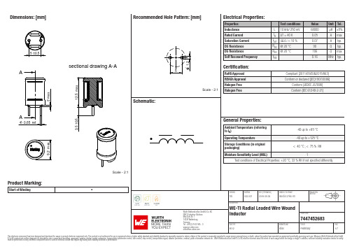
Dimensions: [mm]sectional drawing A-AScale - 2:1Product Marking:Start of Winding•7447452683744745268374474526837447452683T e m p e r a t u r eT T T 7447452683Cautions and Warnings:The following conditions apply to all goods within the product series of WE-TI of Würth Elektronik eiSos GmbH & Co. KG:General:•This electronic component was designed and manufactured for use in general electronic equipment.•Würth Elektronik must be asked for written approval (following the PPAP procedure) before incorporating the components into any equipment in fields such as military, aerospace, aviation, nuclear control, submarine, transportation (automotive control, train control, ship control), transportation signal, disaster prevention, medical, public information network, etc. where higher safety and reliability are especially required and/or if there is the possibility of direct damage or human injury.•Electronic components that will be used in safety-critical or high-reliability applications, should be pre-evaluated by the customer. •The component is designed and manufactured to be used within the datasheet specified values. If the usage and operation conditions specified in the datasheet are not met, the wire insulation may be damaged or dissolved.•Do not drop or impact the components, the component may be damaged.•Würth Elektronik products are qualified according to international standards, which are listed in each product reliability report. Würth Elektronik does not warrant any customer qualified product characteristics beyond Würth Elektroniks’ specifications, for its validity and sustainability over time.•The customer is responsible for the functionality of their own products. All technical specifications for standard products also apply to customer specific products.Product specific:Soldering:•The solder profile must comply with the technical product specifications. All other profiles will void the warranty.•All other soldering methods are at the customers’ own risk.Cleaning and Washing:•Washing agents used during the production to clean the customer application might damage or change the characteristics of the wire insulation, marking or plating. Washing agents may have a negative effect on the long-term functionality of the product. Potting:•If the product is potted in the costumer application, the potting material might shrink or expand during and after hardening. Shrinking could lead to an incomplete seal, allowing contaminants into the core. Expansion could damage the components. We recommend a manual inspection after potting to avoid these effects. Storage Conditions:• A storage of Würth Elektronik products for longer than 12 months is not recommended. Within other effects, the terminals may suffer degradation, resulting in bad solderability. Therefore, all products shall be used within the period of 12 months based on the day of shipment.•Do not expose the components to direct sunlight.•The storage conditions in the original packaging are defined according to DIN EN 61760-2.•The storage conditions stated in the original packaging apply to the storage time and not to the transportation time of the components. Packaging:•The packaging specifications apply only to purchase orders comprising whole packaging units. If the ordered quantity exceeds or is lower than the specified packaging unit, packaging in accordance with the packaging specifications cannot be ensured. Handling:•Violation of the technical product specifications such as exceeding the nominal rated current will void the warranty.•Applying currents with audio-frequency signals might result in audible noise due to the magnetostrictive material properties. •Due to heavy weight of the components, strong forces and high accelerations might have the effect to damage the electrical connection or to harm the circuit board and will void the warranty.•Please be aware that products provided in bulk packaging may get bent and might lead to derivations from the mechanical manufacturing tolerances mentioned in our datasheet, which is not considered to be a material defect.•The temperature rise of the component must be taken into consideration. The operating temperature is comprised of ambient temperature and temperature rise of the component.The operating temperature of the component shall not exceed the maximum temperature specified.These cautions and warnings comply with the state of the scientific and technical knowledge and are believed to be accurate and reliable.However, no responsibility is assumed for inaccuracies or incompleteness.Würth Elektronik eiSos GmbH & Co. KGEMC & Inductive SolutionsMax-Eyth-Str. 174638 WaldenburgGermanyCHECKED REVISION DATE (YYYY-MM-DD)GENERAL TOLERANCE PROJECTIONMETHODTRi002.0072019-08-05DIN ISO 2768-1mDESCRIPTIONWE-TI Radial Leaded Wire WoundInductor ORDER CODE7447452683SIZE/TYPE BUSINESS UNIT STATUS PAGEImportant NotesThe following conditions apply to all goods within the product range of Würth Elektronik eiSos GmbH & Co. KG:1. General Customer ResponsibilitySome goods within the product range of Würth Elektronik eiSos GmbH & Co. KG contain statements regarding general suitability for certain application areas. These statements about suitability are based on our knowledge and experience of typical requirements concerning the areas, serve as general guidance and cannot be estimated as binding statements about the suitability for a customer application. The responsibility for the applicability and use in a particular customer design is always solely within the authority of the customer. Due to this fact it is up to the customer to evaluate, where appropriate to investigate and decide whether the device with the specific product characteristics described in the product specification is valid and suitable for the respective customer application or not.2. Customer Responsibility related to Specific, in particular Safety-Relevant ApplicationsIt has to be clearly pointed out that the possibility of a malfunction of electronic components or failure before the end of the usual lifetime cannot be completely eliminated in the current state of the art, even if the products are operated within the range of the specifications.In certain customer applications requiring a very high level of safety and especially in customer applications in which the malfunction or failure of an electronic component could endanger human life or health it must be ensured by most advanced technological aid of suitable design of the customer application that no injury or damage is caused to third parties in the event of malfunction or failure of an electronic component. Therefore, customer is cautioned to verify that data sheets are current before placing orders. The current data sheets can be downloaded at .3. Best Care and AttentionAny product-specific notes, cautions and warnings must be strictly observed. Any disregard will result in the loss of warranty.4. Customer Support for Product SpecificationsSome products within the product range may contain substances which are subject to restrictions in certain jurisdictions in order to serve specific technical requirements. Necessary information is available on request. In this case the field sales engineer or the internal sales person in charge should be contacted who will be happy to support in this matter.5. Product R&DDue to constant product improvement product specifications may change from time to time. As a standard reporting procedure of the Product Change Notification (PCN) according to the JEDEC-Standard inform about minor and major changes. In case of further queries regarding the PCN, the field sales engineer or the internal sales person in charge should be contacted. The basic responsibility of the customer as per Section 1 and 2 remains unaffected.6. Product Life CycleDue to technical progress and economical evaluation we also reserve the right to discontinue production and delivery of products. As a standard reporting procedure of the Product Termination Notification (PTN) according to the JEDEC-Standard we will inform at an early stage about inevitable product discontinuance. According to this we cannot guarantee that all products within our product range will always be available. Therefore it needs to be verified with the field sales engineer or the internal sales person in charge about the current product availability expectancy before or when the product for application design-in disposal is considered. The approach named above does not apply in the case of individual agreements deviating from the foregoing for customer-specific products.7. Property RightsAll the rights for contractual products produced by Würth Elektronik eiSos GmbH & Co. KG on the basis of ideas, development contracts as well as models or templates that are subject to copyright, patent or commercial protection supplied to the customer will remain with Würth Elektronik eiSos GmbH & Co. KG. Würth Elektronik eiSos GmbH & Co. KG does not warrant or represent that any license, either expressed or implied, is granted under any patent right, copyright, mask work right, or other intellectual property right relating to any combination, application, or process in which Würth Elektronik eiSos GmbH & Co. KG components or services are used.8. General Terms and ConditionsUnless otherwise agreed in individual contracts, all orders are subject to the current version of the “General Terms and Conditions of Würth Elektronik eiSos Group”, last version available at .Würth Elektronik eiSos GmbH & Co. KGEMC & Inductive SolutionsMax-Eyth-Str. 174638 WaldenburgGermanyCHECKED REVISION DATE (YYYY-MM-DD)GENERAL TOLERANCE PROJECTIONMETHODTRi002.0072019-08-05DIN ISO 2768-1mDESCRIPTIONWE-TI Radial Leaded Wire WoundInductor ORDER CODE7447452683SIZE/TYPE BUSINESS UNIT STATUS PAGE。
SMBJ5.0CA中文资料
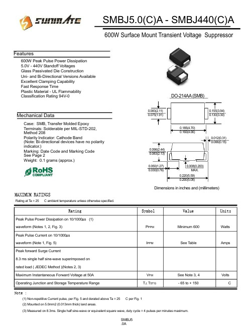
SMBJ5.0(C)A - SMBJ440(C)A600W Surface Mount Transient Voltage SuppressorFeatures600W Peak Pulse Power Dissipation5.0V - 440V Standoff VoltagesGlass Passivated Die ConstructionUni- and Bi-Directional Versions AvailableExcellent Clamping CapabilityFast Response TimePlastic Material - UL FlammabilityClassification Rating 94V-0Mechanical DataCase: SMB, Transfer Molded EpoxyTerminals: Solderable per MIL-STD-202,Method 208Polarity Indicator: Cathode Band(Note: Bi-directional devices have no polarityindicator.)Marking: Date Code and Marking CodeSee Page 2Weight: 0.1 grams (approx.)MAXIMUM RATINGSRating at T a = 25 C ambient temperature unless otherwise specified.DO-214AA (SMB)0.083(2.11) 0.155(3.94) 0.075(1.91) 0.130(3.30)0.185(4.70)0.160(4.06)0.012(0.31)0.006(0.15) 0.096(2.44)0.083(2.13)0.050(1.27) 0.008(0.203)0.030(0.76) MAX.0.220(5.59)0.200(5.08)Dimensions in inches and (millimeters)Rating Symbol Value Units Peak Pulse Power Dissipation on 10/1000μs (1)waveform (Notes 1, 2, Fig. 3) P PPM Minimum 600 Watts Peak Pulse Current on 10/1000μswaveform (Note 1, Fig. 5) I PPM See T able Amps Peak forward Surge Current8.3 ms single half sine-wave superimposed onrated load ( JEDEC Method )(Notes 2, 3)Maximum Instantaneous Forward Voltage at 50A V FM See Note 3, 4 Volts Operating Junction and Storage T emperature Range T J, T STG - 65 to + 150 CNote :(1) Non-repetitive Current pulse, per Fig. 5 and derated above Ta = 25 C per Fig. 1(2) Mounted on 5.0mm2 (0.013mm thick) land areas.(3) Measured on 8.3ms. Single half sine-wave or equivalent square wave, duty cycle = 4 pulses per minutes maximum.SMBJ5.0ATYPE MarkingReverse BreakdownStand-Off VoltageVoltage Min. @I TBreakdownVoltage TestMax. @ I T CurrentMaximumClampingVoltage@I PPPeak ReversePulse LeakageCurrent @V RMW(Uni) (BI) (Uni) (Bi) V RMW (V) V BR MIN(V) V BR MAX(V) I T (mA) V C(V) I PP(A) I R(uA) SMBJ5.0 SMBJ5.0C KD AD 5.0 6.40 7.55 10 9.6 62.5 800.0 SMBJ5.0A SMBJ5.0CA KE AE 5.0 6.40 7.25 10 9.2 65.2 800.0 SMBJ6.0 SMBJ6.0C KF AF 6.0 6.67 8.45 10 11.4 52.6 800.0 SMBJ6.0A SMBJ6.0CA KG AG 6.0 6.67 7.67 10 10.3 58.3 800.0 SMBJ6.5 SMBJ6.5C KH AH 6.5 7.22 9.14 10 12.3 48.8 500.0 SMBJ6.5A SMBJ6.5CA KK AK 6.5 7.22 8.30 10 11.2 53.6 500.0 SMBJ7.0 SMBJ7.0C KL AL 7.0 7.78 9.86 10 13.3 45.1 200.0 SMBJ7.0A SMBJ7.0CA KM AM 7.0 7.78 8.95 10 12.0 50.0 200.0 SMBJ7.5 SMBJ7.5C KN AN 7.5 8.33 10.67 1.0 14.3 42.0 100.0 SMBJ7.5A SMBJ7.5CA KP AP 7.5 8.33 9.58 1.0 12.9 46.5 100.0 SMBJ8.0 SMBJ8.0C KQ AQ 8.0 8.89 11.3 1.0 15.0 40.0 50.0 SMBJ8.0A SMBJ8.0CA KR AR 8.0 8.89 10.23 1.0 13.6 44.1 50.0 SMBJ8.5 SMBJ8.5C KS AS 8.5 9.44 11.92 1.0 15.9 37.7 20.0 SMBJ8.5A SMBJ8.5CA KT AT 8.5 9.44 10.82 1.0 14.4 41.7 20.0 SMBJ9.0 SMBJ9.0C KU AU 9.0 10.0 12.6 1.0 16.9 35.5 10.0 SMBJ9.0A SMBJ9.0CA KV AV 9.0 10.0 11.5 1.0 15.4 39.0 10.0 SMBJ10 SMBJ10C KW AW 10 11.1 14.1 1.0 18.8 31.9 5.0 SMBJ10A SMBJ10CA KX AX 10 11.1 12.8 1.0 17.0 35.3 5.0 SMBJ11 SMBJ11C KY AY 11 12.2 15.4 1.0 20.1 29.9 5.0 SMBJ11A SMBJ11CA KZ AZ 11 12.2 14.0 1.0 18.2 33.0 5.0 SMBJ12 SMBJ12C LD BD 12 13.3 16.9 1.0 22.0 27.3 5.0 SMBJ12A SMBJ12CA LE BE 12 13.3 15.3 1.0 19.9 30.2 5.0 SMBJ13 SMBJ13C LF BF 13 14.4 18.2 1.0 23.8 25.2 5.0 SMBJ13A SMBJ13CA LG BG 13 14.4 16.5 1.0 21.5 27.9 5.0 SMBJ14 SMBJ14C LH BH 14 15.6 19.8 1.0 25.8 23.3 5.0 SMBJ14A SMBJ14CA LK BK 14 15.6 17.9 1.0 23.2 25.9 5.0 SMBJ15 SMBJ15C LL BL 15 16.7 21.1 1.0 26.9 22.3 5.0 SMBJ15A SMBJ15CA LM BM 15 16.7 19.2 1.0 24.4 24.6 5.0 SMBJ16 SMBJ16C LN BN 16 17.8 22.6 1.0 28.8 20.8 5.0 SMBJ16A SMBJ16CA LP BP 16 17.8 20.5 1.0 26.0 23.1 5.0 SMBJ17 SMBJ17C LQ BQ 17 18.9 23.9 1.0 30.5 19.7 5.0 SMBJ17A SMBJ17CA LR BR 17 18.9 21.7 1.0 27.6 21.7 5.0 SMBJ18 SMBJ18C LS BS 18 20.0 25.3 1.0 32.2 18.6 5.0 SMBJ18A SMBJ18CA LT BT 18 20.0 23.3 1.0 29.2 20.5 5.0 SMBJ20 SMBJ20C LU BU 20 22.2 28.1 1.0 35.8 16.8 5.0 SMBJ20A SMBJ20CA LV BV 20 22.2 25.5 1.0 32.4 18.5 5.0 SMBJ22 SMBJ22C LW BW 22 24.4 30.9 1.0 39.4 15.2 5.0 SMBJ22A SMBJ22CA LX BX 22 24.4 28.0 1.0 35.5 16.9 5.0 SMBJ24 SMBJ24C LY BY 24 26.7 33.8 1.0 43.0 14.0 5.0 SMBJ24A SMBJ24CA LZ BZ 24 26.7 30.7 1.0 38.9 15.4 5.0 SMBJ26 SMBJ26C MD CD 26 28.9 36.6 1.0 46.6 12.9 5.0 SMBJ26A SMBJ26CA ME CE 26 28.9 33.2 1.0 42.1 14.3 5.0 SMBJ28 SMBJ28C MF CF 28 31.1 39.4 1.0 50.0 12.0 5.0 SMBJ28A SMBJ28CA MG CG 28 31.1 35.8 1.0 45.4 13.2 5.0 Note:( 1 ) V BR measured after I T applied for 300 s., I T = square wave pulse or equivalent. ( 2 )Surge Current Waveform per Figure 5 and Derate per Figure 1( 3 ) A Transient suppressor is normally selected according to the reverse " Stand-off Voltage " (V WM) which should beequal to or greater then the D.C. or continuous peak operating voltage level.SMBJ5.0AReverse Breakdown Breakdown Maximum Peak Reverse TYPE Marking Stand-Off Voltage Voltage Test Clamping Pulse LeakageVoltage Min. @I T Max. @ I T Current Voltage @I PP Current @V RMW (Uni) (BI) (Uni) (Bi) V RMW (V) V BR MIN(V) V BR MAX(V) I T (mA) V C(V) I PP(A) I R(uA) SMBJ30 SMBJ30C MH CH 30 33.3 42.2 1.0 53.5 11.2 5.0 SMBJ30A SMBJ30CA MK CK 30 33.3 38.3 1.0 48.4 12.4 5.0 SMBJ33 SMBJ33C ML CL 33 36.7 46.5 1.0 59.0 10.2 5.0 SMBJ33A SMBJ33CA MM CM 33 36.7 42.2 1.0 53.3 11.3 5.0 SMBJ36 SMBJ36C MN CN 36 40.0 50.7 1.0 64.3 9.3 5.0 SMBJ36A SMBJ36CA MP CP 36 40.0 46.0 1.0 58.1 10.3 5.0 SMBJ40 SMBJ40C MQ CQ 40 44.4 56.3 1.0 71.4 8.4 5.0 SMBJ40A SMBJ40CA MR CR 40 44.4 51.1 1.0 64.5 9.3 5.0 SMBJ43A SMBJ43CA MT CT 43 47.8 54.9 1.0 69.4 8.6 5.0 SMBJ45 SMBJ45C MU CU 45 50.0 63.3 1.0 80.3 7.5 5.0 SMBJ45A SMBJ45CA MV CV 45 50.0 57.5 1.0 72.7 8.3 5.0 SMBJ48 SMBJ48C MW CW 48 53.3 67.5 1.0 85.5 7.0 5.0 SMBJ48A SMBJ48CA MX CX 48 53.3 61.3 1.0 77.4 7.8 5.0 SMBJ51 SMBJ51C MY CY 51 56.7 71.8 1.0 91.1 6.6 5.0 SMBJ51A SMBJ51CA MZ CZ 51 56.7 65.2 1.0 82.4 7.3 5.0 SMBJ54 SMBJ54C ND DD 54 60.0 76.0 1.0 96.3 6.2 5.0 SMBJ54A SMBJ54CA NE DE 54 60.0 69.0 1.0 87.1 6.9 5.0 SMBJ58 SMBJ58C NF DF 58 64.4 81.6 1.0 103 5.8 5.0 SMBJ58A SMBJ58CA NG DG 58 64.4 74.1 1.0 93.6 6.4 5.0 SMBJ60 SMBJ60C NH DH 60 66.7 84.5 1.0 107 5.6 5.0 SMBJ60A SMBJ60CA NK DK 60 66.7 76.7 1.0 96.8 6.2 5.0 SMBJ64 SMBJ64C NL DL 64 71.1 90.1 1.0 114 5.3 5.0 SMBJ64A SMBJ64CA NM DM 64 71.1 81.8 1.0 103 5.8 5.0 SMBJ70 SMBJ70C NN DN 70 77.8 98.6 1.0 125 4.8 5.0 SMBJ70A SMBJ70CA NP DP 70 77.8 89.5 1.0 113 5.3 5.0 SMBJ75 SMBJ75C NQ DQ 75 83.0 105.7 1.0 134 4.5 5.0 SMBJ75A SMBJ75CA NR DR 75 83.0 95.8 1.0 121 5.0 5.0 SMBJ90 SMBJ90C NW DW 90 100 126.5 1.0 160 3.8 5.0 SMBJ90A SMBJ90CA NX DX 90 100 115.5 1.0 146 4.1 5.0 SMBJ100 SMBJ100C NY DY 100 111 141.0 1.0 179 3.4 5.0 SMBJ100A SMBJ100CA NZ DZ 100 111 128.0 1.0 162 3.7 5.0 SMBJ110 SMBJ110C PD ED 110 122 154.5 1.0 196 3.1 5.0 SMBJ110A SMBJ110CA PE EE 100 122 140.5 1.0 177 3.4 5.0 SMBJ120 SMBJ120C PF EF 120 133 169.0 1.0 214 2.8 5.0 SMBJ120A SMBJ120CA PG EG 120 133 153.0 1.0 193 3.1 5.0 SMBJ130 SMBJ130C PH EH 130 144 182.5 1.0 231 2.6 5.0 SMBJ130A SMBJ130CA PK EK 130 144 165.5 1.0 209 2.9 5.0 SMBJ150 SMBJ150C PL EL 150 167 211.5 1.0 268 2.2 5.0 SMBJ150A SMBJ150CA PM EM 150 167 192.5 1.0 243 2.5 5.0 SMBJ160 SMBJ160C PN EN 160 178 226.0 1.0 287 2.1 5.0 SMBJ160A SMBJ160CA PP EP 160 178 205.0 1.0 259 2.3 5.0 Note:( 1 ) V BR measured after I T applied for 300 s., I T = square wave pulse or equivalent. ( 2 )Surge Current Waveform per Figure 5 and Derate per Figure 1( 3 ) A Transient suppressor is normally selected according to the reverse " Stand-off Voltage " (V WM) which should beequal to or greater then the D.C. or continuous peak operating voltage level.SMBJ5.0ATYPE MarkingReverse BreakdownStand-Off VoltageVoltage Min. @I TBreakdownVoltage TestMax. @ I T CurrentMaximumClampingVoltage@I PPPeak ReversePulse LeakageCurrent @V RMW(Uni) (BI) (Uni) (Bi) V RMW (V) V BR MIN(V) V BR MAX(V) I T (mA) V C(V) I PP(A) I R(uA) SMBJ170 SMBJ170C PQ EQ 170 189 239.5 1.0 304 2.0 5.0 SMBJ170A SMBJ170CA PR ER 170 189 217.5 1.0 275 2.2 5.0 SMBJ180 SMBJ180C PS ES 180 200 253.8 1.0 321 1.9 5.0 SMBJ180A SMBJ180CA PT ET 180 200 230.4 1.0 290 2.1 5.0 SMBJ190 SMBJ190C PU EU 190 211 267.9 1.0 339 1.8 5.0 SMBJ190A SMBJ190CA PV EV 190 211 243.2 1.0 306 2.0 5.0 SMBJ200 SMBJ200C PW EW 200 222 282.0 1.0 356 1.7 5.0 SMBJ200A SMBJ200CA PX EX 200 222 256.0 1.0 322 1.9 5.0 SMBJ210 SMBJ210C PY EY 210 233 296.1 1.0 375 1.6 5.0 SMBJ210A SMBJ210CA PZ EZ 210 233 268.8 1.0 339 1.8 5.0 SMBJ220 SMBJ220C QD FD 220 244 310.2 1.0 392 1.5 5.0 SMBJ220A SMBJ220CA QE FE 220 244 281.6 1.0 355 1.7 5.0 SMBJ250 SMBJ250C QF FF 250 278 342.5 1.0 447 1.3 5.0 SMBJ250A SMBJ250CA QG FG 250 278 309.0 1.0 403 1.5 5.0 SMBJ300 SMBJ300C QH FH 300 333 411.0 1.0 535 1.1 5.0 SMBJ300A SMBJ300CA QK FK 300 333 371.0 1.0 484 1.2 5.0 SMBJ350 SMBJ350C QL FL 350 389 479.5 1.0 624 1.0 5.0 SMBJ350A SMBJ350CA QM FM 350 389 432.0 1.0 565 1.1 5.0 SMBJ400 SMBJ400C QN FN 400 444 548.0 1.0 687 0.9 5.0 SMBJ400A SMBJ400CA QP FP 400 444 494.0 1.0 645 0.9 5.0 SMBJ440 SMBJ440C QQ FQ 440 489 602.8 1.0 786 0.8 5.0 SMBJ440A SMBJ440CA QR FR 440 489 543.0 1.0 710 0.8 5.0SMBJ5.0ARatings and Characteristic Curves T A =25癈 unless otherwise notedSMBJ5.0A。
CommScope FSJ4-50B HELIAX Superflexible Foam Coaxi

FSJ4-50B, HELIAX® Superflexible Foam Coaxial Cable, corrugatedcopper, 1/2 in, black PE jacket (Halogen free jacketing non-fire-retardant)Product ClassificationProduct Type Coaxial wireless cableProduct Brand HELIAX® | SureFlex®Product Series FSJ4-50BOrdering Note CommScope® standard product (Global)General SpecificationsProduct Number520093902/00 | SZ520093902/00Flexibility SuperflexibleJacket Color BlackPerformance Note Attenuation values typical, guaranteed within 5%DimensionsDiameter Over Dielectric8.89 mm | 0.35 inDiameter Over Jacket13.462 mm | 0.53 inInner Conductor OD 3.556 mm | 0.14 inOuter Conductor OD12.192 mm | 0.48 inNominal Size1/2 inElectrical SpecificationsCable Impedance50 ohm ±1 ohmCapacitance82.7 pF/m | 25.207 pF/ftdc Resistance, Inner Conductor 2.69 ohms/km | 0.82 ohms/kftdc Resistance, Outer Conductor 5.12 ohms/km | 1.561 ohms/kftdc Test Voltage2500 VInductance0.207 µH/m | 0.063 µH/ft100000 MOhms-km15Page ofInsulation Resistance100000 MOhms-kmJacket Spark Test Voltage (rms)5000 VOperating Frequency Band 1 – 10200 MHzPeak Power22.5 kWVelocity81 %AttenuationFrequency (MHz)Attenuation (dB/100 m)Attenuation (dB/100 ft)Average Power (kW)1.00.3270.122.51.50.4010.12222.52.00.4630.14122.510.0 1.0440.31810.1420.0 1.4850.4537.1230.0 1.8280.557 5.7950.0 2.3770.724 4.4585.0 3.130.954 3.3888.0 3.1870.971 3.32100.0 3.406 1.038 3.11108.0 3.546 1.081 2.98150.0 4.214 1.285 2.51174.0 4.558 1.389 2.32200.0 4.908 1.496 2.16204.0 4.96 1.512 2.13300.0 6.095 1.858 1.74400.07.121 2.17 1.49450.07.592 2.314 1.39460.07.684 2.342 1.38500.08.042 2.451 1.32512.08.148 2.483 1.3600.08.891 2.71 1.19700.09.683 2.951 1.09800.010.431 3.179 1.01824.010.605 3.2321894.011.101 3.3830.95960.011.555 3.5220.9211.824 3.6040.8925Page of1000.011.824 3.6040.891218.013.226 4.0310.81250.013.423 4.0910.791500.014.906 4.5430.711700.016.027 4.8850.661794.016.537 5.040.641800.016.57 5.050.642000.017.624 5.3710.62100.018.137 5.5280.582200.018.641 5.6820.572300.019.138 5.8330.552500.020.11 6.1290.532700.021.056 6.4180.53000.022.432 6.8370.473400.024.1987.3750.443600.025.0557.6360.423700.025.4787.7650.423800.025.8987.8930.413900.026.3148.020.44000.026.7278.1460.44100.027.1368.2710.394200.027.5428.3940.384300.027.9468.5170.384400.028.3468.6390.374500.028.7448.7610.374600.029.1398.8810.364700.029.5319.0010.364800.029.9219.1190.354900.030.3089.2380.355000.030.6939.3550.346000.034.42710.4930.318000.041.40312.6190.268800.044.05413.4270.2410000.047.91414.6030.22Material Specifications35Page ofDielectric Material Foam PEJacket Material PEInner Conductor Material Copper-clad aluminum wireOuter Conductor Material Corrugated copperMechanical SpecificationsMinimum Bend Radius, multiple Bends31.75 mm | 1.25 inMinimum Bend Radius, single Bend31.75 mm | 1.25 inNumber of Bends, minimum20Number of Bends, typical50Tensile Strength79 kg | 174.165 lbBending Moment 2.7 N-m | 23.897 in lbFlat Plate Crush Strength 2 kg/mm | 111.995 lb/inEnvironmental SpecificationsInstallation temperature-40 °C to +60 °C (-40 °F to +140 °F)Operating Temperature-55 °C to +85 °C (-67 °F to +185 °F)Storage Temperature-70 °C to +85 °C (-94 °F to +185 °F)Attenuation, Ambient Temperature68 °F | 20 °CAverage Power, Ambient Temperature104 °F | 40 °CAverage Power, Inner Conductor Temperature212 °F | 100 °CPackaging and WeightsCable weight0.21 kg/m | 0.141 lb/ftRegulatory Compliance/CertificationsAgency ClassificationCENELEC EN 50575 compliant, Declaration of Performance (DoP) availableCHINA-ROHS Below maximum concentration valueISO 9001:2015Designed, manufactured and/or distributed under this quality management systemREACH-SVHC Compliant as per SVHC revision on /ProductComplianceROHS CompliantUK-ROHS Compliant45Page ofPage of 55。
- 1、下载文档前请自行甄别文档内容的完整性,平台不提供额外的编辑、内容补充、找答案等附加服务。
- 2、"仅部分预览"的文档,不可在线预览部分如存在完整性等问题,可反馈申请退款(可完整预览的文档不适用该条件!)。
- 3、如文档侵犯您的权益,请联系客服反馈,我们会尽快为您处理(人工客服工作时间:9:00-18:30)。
MSC1299.PDF
ISO 9001 CERTIFIED
REV E 10/19/99
元器件交易网
HSMBJ5913B thru HSMBJ5956B
NOTE 1: No suffix indicates a ±20% tolerance on nominal VZ. Suffix A denotes a ±10% tolerance, B denotes a ±5% tolerance, C denotes ±2% tolerance, and D denotes a ±1% tolerance. VZ is measured with diode TL at 30°C and thermal equilibrium. NOTE 2: Zener impedance is derived from the 1 kHz ac voltage which results when an ac current having an rms value equal to 10% of dc zener current (IZT or IZK) superimposed on IZT or IZK. NOTE 3: Based upon 3 W maximum power dissipation. Allowance has been made for the higher voltage associated with higher currents and temperature. For determination of voltage change with current deviations from IZT see Micro Note 202.
HSMBJ5913B HSMBJ5914B HSMBJ5915B HSMBJ5916B HSMBJ5917B HSMBJ5918B HSMBJ5919B HSMBJ5920B HSMBJ5921B HSMBJ5922B HSMBJ5923B HSMBJ5924B HSMBJ5925B HSMBJ5926B HSMBJ5927B HSMBJ5928B HSMBJ5929B HSMBJ5930B HSMBJ5931B HSMBJ5932B HSMBJ5933B HSMBJ5934B HSMBJ5935B HSMBJ5936B HSMBJ5937B HSMBJ5938B HSMBJ5939B HSMBJ5940B HSMBJ5941B HSMBJ5942B HSMBJ5943B HSMBJ5944B HSMBJ5945B HSMBJ5946B HSMBJ5947B HSMBJ5948B HSMBJ5949B HSMBJ5950B HSMBJ5951B HSMBJ5952B HSMBJ5953B HSMBJ5954B HSMBJ5955B HSMBJ5956B
MAXIMUM RATINGS:
• • • • Junction and Storage Temperature: -55°C to +150°C DC Power Dissipation 3 W at Lead Temp. TL ≤75°C Derate above +75°C: 40 mW/°C Forward voltage @ 200mA: 1.2Volts and TL = 30°C
Mechanical Characteristics
• • • • • Case: Similar to DO-214AA Terminals: Leads tin plated Thermal resistance: 25°C/W (maximum) junction to lead at mounting plane Polarity: Cathode indicated by a band Packaging: Standard 12 mm tape 2500 per 13 inch reel see (EIA Standard RS-481)
Electrical Characteristics @ TL = 30°C
PART NUMBER ZENNER VOLTAGE VT (NOTE 1) Volts 3.3 3.6 3.9 4.3 4.7 5.1 5.6 6.2 6.8 7.5 8.2 9.1 10 11 12 13 15 16 18 20 22 24 27 30 33 36 39 43 47 51 56 62 68 75 82 91 100 110 120 130 150 160 180 200 TEST CURRENT I ZT mA 113.6 104.2 96.1 87.2 79.8 73.5 66.9 60.5 55.1 50.0 45.7 41.2 37.5 34.1 31.2 28.9 25.0 23.4 20.8 18.7 17.0 15.6 13.9 12.5 11.4 10.4 9.6 8.7 8.0 7.3 6.7 6.0 5.5 5.0 4.6 4.1 3.7 3.4 3.1 2.9 2.5 2.3 2.1 1.9 DYNAMIC IMPEDANCE ZZT (NOTE 2) Ohms 10.0 9.0 7.5 6.0 5.0 4.0 2.0 2.0 2.5 3.0 3.5 4.0 4.5 5.5 6.5 7.0 9.0 10.0 12.0 14.0 17.5 19.0 23.0 28.0 33.0 38.0 45.0 53.0 67.0 70.0 86.0 100 120 140 160 200 250 300 280 450 600 700 900 1200 KNEE CURRENT I ZK mA 1.0 1.0 1.0 1.0 1.0 1.0 1.0 1.0 1.0 0.5 0.5 0.5 0.25 0.25 0.25 0.25 0.25 0.25 0.25 0.25 0.25 0.25 0.25 0.25 0.25 0.25 0.25 0.25 0.25 0.25 0.25 0.25 0.25 0.25 0.25 0.25 0.25 0.25 0.25 0.25 0.25 0.25 0.25 0.25 KNEE IMPEDANCE ZZK (NOTE 2) OHMS 500 500 500 500 500 350 250 200 200 400 400 500 500 550 550 550 600 600 650 650 650 700 700 750 800 850 900 950 1000 1100 1300 1500 1700 2000 2500 3000 3100 4000 4500 5000 6000 6500 7000 8000 REVERSE CURRENT IR µ Adc 100.0 75.0 25.0 5.0 5.0 5.0 5.0 5.0 5.0 5.0 5.0 5.0 5.0 1.0 1.0 1.0 1.0 1.0 1.0 1.0 1.0 1.0 1.0 1.0 1.0 1.0 1.0 1.0 1.0 1.0 1.0 1.0 1.0 1.0 1.0 1.0 1.0 1.0 1.0 1.0 1.0 1.0 1.0 1.0 REVERSE VOLTAGE VR Volts 1.0 1.0 1.0 1.0 1.5 2.0 3.0 4.0 5.2 6.0 6.5 7.0 8.0 8.4 9.1 9.9 11.4 12.2 13.7 15.2 16.7 18.2 20.6 22.8 25.1 27.4 29.7 32.7 35.8 38.8 42.6 47.1 51.2 56.0 62.2 69.2 76.0 83.6 91.2 98.8 114.0 121.6 136.8 152.0 MAX.DC CURRENT I ZM (NOTE 3) MA 749 686 633 574 526 485 440 397 363 330 300 270 247 206 206 189 165 153 137 124 112 102 91 83 74 68 63 56 51 48 43 40 36 33 30 26 25 22 20 18 17 15 13 12
Pd Maximum Power Dissipation (mW)
T L Lead Temperature at Mounting Plane
MSC1299.PDF
ISO 9001 CERTIFIED
REV E 10/19/99
DIM A B C D E F G
DIMENSIONS INCHES MILLIMETERS MIN MAX MIN MAX .073 .087 1.85 2.21 .160 .180 4.06 4.57 .130 .155 3.30 3.94 .205 .220 5.21 5.59 .075 .130 1.91 3.30 .030 .060 .76 1.52 .006 .016 .15 .41
元器件交易网
8700 E. Thomas Road Scottsdale, AZ 85251 Tel: (480) 941-6300 Fax (480) 947-1503
HSMBJ5913B thru HSMBJ5956B
SILICON 3.0 W ZENER DIODE
FEATURES:
• • • • Surface mount equivalent to 1N5913B thru 1N5956B Popular HSMBJ Package outline-Small and Rugged Zener voltage 3.3V to 200V Constructed with an Oxide Passivated All Diffused Die