戴尔 DELA018 DELL 2007WFP
笔记本各种功能键大全
笔记本各种功能键大全Fn的最主要作用是实现快捷键,例如屏幕亮度调整,音量调整,关闭屏幕,待机等,都可以通过Fn+特定的快捷键实现。
还有笔记本由于尺寸限制,往往没有专门的数字键盘,而是通过Fn+Number Lock让部分键盘成为数字键盘。
可以说,Fn是一个功能相当强大的笔记本:Fn+F1为休眠功能,Fn+F2为无线网卡开关,Fn+F3为显示切换,Fn+F4和Fn+F5 为亮度调节,Fn+F6为静音,FnF7和Fn+F8为音量调节。
几种不同型号笔记本的FN键功能:SONY篇为SONY的快捷键有很多都在WINDOWS环境下才能使用,所以需要软件支持。
例如FN要和其它键组合使用需要安装HotKey Utility这一软件FN+ESC:设置为等待状态FN+F3:静音(只有在WINDOWS有效)FN+F4:弹出音量调节状态条(只有在WINDOWS有效)FN+F5:弹出亮度调节条FN+F7:切换显示器FN+F12:将系统设置为休眠状态FN+NUMLK:按下等于SCROLL LOCK键FN+Insert:按下等于PAUSE键FN+Delete:按下等于BREAK键FN+向上方向键:按下等于PAGE UP键FN+向下方向键:按下等于PAGE DOWN键FN+向右方向键:按下等于HOME键FN+向左方向键:按下等于END键FN+F:拉申或者不拉申屏幕(只有在WINDOWS下有用)Dell篇Dell 8000的快捷键级别上是Dell传统的风格,也没有可供用户自定义的独立快捷键,最有特色的地方在于可以用FN+F10直接弹出光驱托盘,这样不但避免了摸索光驱面板上弹出按钮的麻烦,也减少了光驱自身的损耗。
FN+ESC:选择所预设的电源管理模式FN+F2:开启或关闭无线网卡功能DELL8000无)FN+F3:显示电源表FN+F8:切换显示器FN+F10:弹出光驱FN+上方向键/下方向键:增加/减低亮度FN+END:静音FN+PgUp:增加音量FN+PgDn:减低音量FN+Num lock::相当于按下Scroll lock联想联想的FN组合键比较简单,但是它的图标表示比较有个性,即使是笔记本老手都有可能看不懂某些快捷键的图表哦。
戴尔 PowerMax 8000、VMAX All Flash DASD大型主机 产品说明书
DELL EMC 大型主機技術概觀摘要本白皮書將概括說明適用於 IBM Z 和 IBM z/TPF 環境的 Dell EMC 產品方案。
本白皮書的對象為有意瞭解 Dell EMC 大型主機相容性產品,以及 Dell EMC 為 IBM 使用者提供了哪些創新和獨特功能的客戶或潛在客戶。
2019 年 9 月修訂內容確認本白皮書由以下人員製作:作者:Brett Quinn、Bruce Klenk、Paul Scheuer支援:大型主機企業系統工程本出版品的資訊係以「現狀」提供。
Dell Inc. 對本出版品之資訊不做任何表示或保證,尤其不針對適銷性或特定用途的適用性提供默示擔保。
使用、複製及散佈本出版品中所提及之任何軟體,皆需獲得適用的軟體授權。
Copyright © 2019 Dell Inc. 或其子公司。
保留所有權利。
Dell、EMC、Dell EMC 與其他商標均為 Dell Inc. 或其子公司的商標。
Dell®/EMC®/Dell EMC® 等品牌商標將可能同時出現在戴爾易安信企業級產品 (包括硬體和軟體)、產品相關資料及戴爾易安信官方網站。
如果您對戴爾易安信產品有任何疑問,請聯繫您的銷售代表。
其他商標是屬於其各自擁有者之財產。
2019 年 9 月。
白皮書 h6109.9目錄報告摘要 (5)DELL EMC 大型主機產品簡介 (5)適用於大型主機的 Dell EMC 儲存陣列 (5)適用於大型主機的 PowerMax 8000 儲存陣列 (6)適用於大型主機的 VMAX 950F 儲存陣列 (6)PowerMAXOS 和 HYPERMAX OS 中的新大型主機功能 (8)IBM Z 相容性支援 (8)DELL EMC 最佳化工具系列 (9)PAV Optimizer (9)Mirror Optimizer (11)FLASHBOOST (12)資料保護 (12)適用於 z/OS 的 SRDF 產品系列 (12)並行 SRDF (13)串聯式 SRDF (14)SRDF/Star (14)SRDF/SQAR (15)AutoSwap for Z/OS (16)Dell EMC TimeFinder SnapVX for Z/OS (16)ZDP™ – DATA PROTECTOR FOR Z SYSTEMS (17)自 OS 5978 SR (2019 年第 3 季) 起的 ZDP 強化功能 (18)DISK LIBRARY FOR MAINFRAME (DLM) (18)GDDR 為您的資料中心提供自動化、復原和監控功能 (22)受支援的業務持續性組態 (23)Universal Data Consistency:GDDR 與 Disk Library for Mainframe (DLm) (23)GDDR 磁帶– DLm 災難復原 (DR) 容錯移轉自動化解決方案 (24)儲存裝置管理軟體 (25)Mainframe Enablers (25)Unisphere (25)適用於大型主機的 Connectrix B-Series (26)適用於大型主機的 Connectrix MDS Series (27)使用 Z/OS MIGRATOR 進行資料遷移 (27)摘要 (28)報告摘要大型主機平台目前仍是交易處理的重要選項,它可安全容納全球最大的金融、政府、健康照護、保險與製造商企業的「記錄系統」資料。
拆解DELL2007FPb液晶显示器
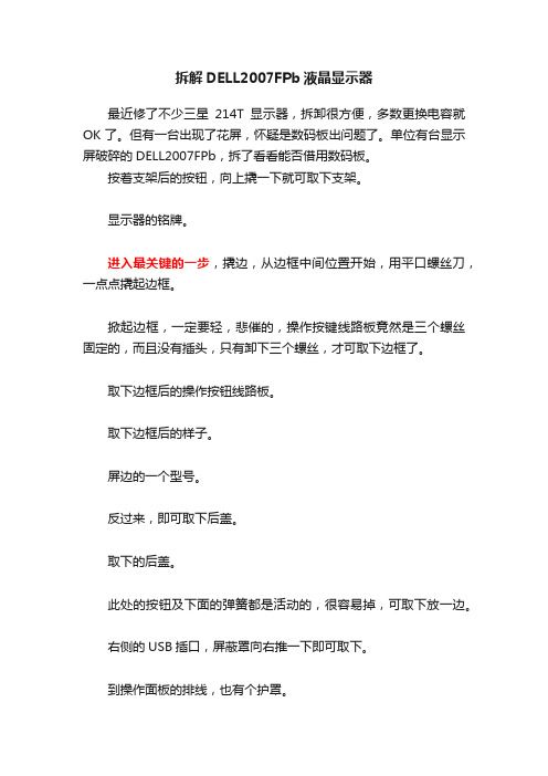
拆解DELL2007FPb液晶显示器最近修了不少三星214T显示器,拆卸很方便,多数更换电容就OK了。
但有一台出现了花屏,怀疑是数码板出问题了。
单位有台显示屏破碎的DELL2007FPb,拆了看看能否借用数码板。
按着支架后的按钮,向上撬一下就可取下支架。
显示器的铭牌。
进入最关键的一步,撬边,从边框中间位置开始,用平口螺丝刀,一点点撬起边框。
掀起边框,一定要轻,悲催的,操作按键线路板竟然是三个螺丝固定的,而且没有插头,只有卸下三个螺丝,才可取下边框了。
取下边框后的操作按钮线路板。
取下边框后的样子。
屏边的一个型号。
反过来,即可取下后盖。
取下的后盖。
此处的按钮及下面的弹簧都是活动的,很容易掉,可取下放一边。
右侧的USB插口,屏蔽罩向右推一下即可取下。
到操作面板的排线,也有个护罩。
继续拆屏侧面的四个螺丝。
下面继续……[ 此帖被welcom321在2012-09-14 06:50重新编辑]最近修了不少三星214T显示器,拆卸很方便,多数更换电容就OK了。
但有一台出现了花屏,怀疑是数码板出问题了。
单位有台显示屏破碎的DELL2007FPb,拆了看看能否借用数码板。
按着支架后的按钮,向上撬一下就可取下支架。
显示器的铭牌。
进入最关键的一步,撬边,从边框中间位置开始,用平口螺丝刀,一点点撬起边框。
掀起边框,一定要轻,悲催的,操作按键线路板竟然是三个螺丝固定的,而且没有插头,只有卸下三个螺丝,才可取下边框了。
取下边框后的操作按钮线路板。
取下边框后的样子。
屏边的一个型号。
反过来,即可取下后盖。
取下的后盖。
此处的按钮及下面的弹簧都是活动的,很容易掉,可取下放一边。
右侧的USB插口,屏蔽罩向右推一下即可取下。
到操作面板的排线,也有个护罩。
继续拆屏侧面的四个螺丝。
左侧保护罩,向上推,取下。
露出接灯管的四个插头,取下。
整个后铁盖,向下滑一下,露出到显示屏的信号插头,轻轻取下。
整个后铁壳即可取下,翻开看看内部样子,慢慢排了四块控制板啊!跟三星完全不是一个模式。
Dell PowerVault MD3400 3420 3800i 3820i 3800f 3820
Matrices de almacenamiento Dell PowerVault MD3400/3420/3800i/3820i/3800f/3820f Guía de introducciónNotas, precauciones y advertenciasUna NOTA indica información importante que le ayuda a hacer un mejor uso de su producto.Una PRECAUCIÓN indica la posibilidad de daños en el hardware o la pérdida de datos, y le explica cómoUn mensaje de AVISO indica el riesgo de daños materiales, lesiones corporales o incluso la muerte.Copyright © 2014 Dell Inc. Todos los derechos reservados. Este producto está protegido por leyes internacionales y de los Estados Unidos sobre los derechos de autor y la propiedad intelectual. Dell™ y el logotipo de Dell son marcas comerciales de Dell Inc. en los Estados Unidos y en otras jurisdicciones. El resto de marcas y nombres que se mencionan en este documento, puede ser marcas comerciales de las compañías respectivas.Instalación y configuraciónAntes de realizar el procedimiento siguiente, revise las instrucciones de seguridad incluidas con el sistema.Temas:•Desembalaje de un sistema rack •Conexión de los cables de alimentación •Fijación de los cables de alimentación •Cómo encender el sistema •Instalación del bisel •Acuerdo de licencia de Dell Software •Otra información útil •Obtención de asistencia técnica •Información de la NOM•Especificaciones técnicasDesembalaje de un sistema rackIlustración 1. Instalación del sistema en un rack Desembale el sistema e identifique cada elemento.Ensamble los rieles e instale el sistema en el rack siguiendo las instrucciones de seguridad y de instalación del rack incluidas con el sistema.1Instalación y configuración 3Conexión de los cables de alimentaciónIlustración 2. Conexión de los cables de alimentaciónConecte los cables de alimentación del sistema al sistema.Fijación de los cables de alimentaciónIlustración 3. Fijación de los cables de alimentaciónAbra el soporte de rentención del cable tirando de las pestañas en los lados, introduzca el cable y asegure el cable de alimentación del sistema, como se muestra en la ilustración.Conecte el otro extremo de los cables de alimentación a una toma de corriente con conexión a tierra o a otra fuente de alimentación, como una fuente de alimentación ininterrumpida (UPS) o una unidad de distribución de alimentación (PDU).4Instalación y configuraciónCómo encender el sistemaIlustración 4. Cómo encender el sistemaGire el conmutador de alimentación hacia la parte posterior del sistema en la posición de encendido. Se debe encender el LED de alimentación.Instalación del biselIlustración 5. Instalación del biselInstale el bisel tal como se muestra en la ilustración.Acuerdo de licencia de Dell SoftwareAntes de utilizar el sistema, lea el Acuerdo de licencia de Dell Software que se incluye. Debe considerar cualquier soporte de software instalado por Dell como una copia de RESPALDO del software instalado en el disco duro de su sistema. Si no acepta las condiciones del contrato, llame al número de teléfono de asistencia al cliente. Los clientes de los Estados Unidos pueden llamar al 800-WWW-DELL (800-999-3355). Los clientes ubicados fuera de los Estados Unidos pueden visitar /support y seleccionar su país o región en la parte superior izquierda de la página.Otra información útilConsulte la información reglamentaria y de seguridad proporcionada con el sistema. La información sobre la •En el Manual del propietario, se proporciona información acerca de las funciones del hardware del sistema y se describe cómo solucionar problemas del sistema e instalar o sustituir componentes del sistema. Este documento está disponible en línea en / support/manuals.Instalación y configuración5•En la Guía del administrador , se proporciona información sobre las funciones del software Administrador de almacenamiento en disco modular y describe cómo configurar y administrar su sistema de disco modular. Este documento está disponible en línea en /support/manuals .•En la Guía de implementación , se proporciona información sobre el cableado del sistema y sobre la instalación y configuración inicial del software Administrador de almacenamiento en disco modular . Este documento está disponible en línea en /support/manuals .•Para obtener vídeos y otros recursos sobre PowerVault MD series, consulte /PVresources .•En la documentación del rack incluida con la solución de rack se describe cómo instalar el sistema en un rack, si es necesario.•En el soporte suministrado con el sistema se incluye documentación y herramientas para configurar y administrar el sistema, incluidaslas relacionadas con el sistema operativo, el software de administración de sistema, las actualizaciones del sistema y los componentes del sistema adquiridos con él.Compruebe si hay actualizaciones en /support/manuals y, si las hay, léalas antes de proceder a laSe recomienda la descarga e instalación del firmware de administración de sistemas en el sistema desdeObtención de asistencia técnicaSi no comprende alguno de los procedimientos descritos en esta guía o si el sistema no funciona del modo esperado, consulte el Owner’s Manual (Manual del propietario ). Dell cuenta con una amplia oferta de capacitación y certificación de hardware. Consulte /training para obtener más información. Es posible que este servicio no se ofrezca en todas las regiones.Información de la NOMLa información que se proporciona a continuación aparece en el dispositivo descrito en este documento, de conformidad con los requisitos de la Norma Oficial Mexicana (NOM):Importador:Dell Inc. de México, S.A. de C.V.Paseo de la Reforma 2620 -11º PisoCol. Lomas Altas11950 México, D.F.Número de modelo:E03J y E04JVoltaje de alimentación:100 – 240 V CAFrecuencia:50/60 HzConsumo eléctrico:8,6 AEspecificaciones técnicas Las especificaciones siguientes son únicamente las que deben incluirse por ley con el envío del equipo. Para AlimentaciónFuente de alimentación de CA (por fuente de alimentación)Potencia600 WLa disipación de calor se calcula utilizando100 W Voltaje 100–240 VCA (8,6 A–4,3 A)6Instalación y configuraciónAlimentaciónEste sistema ha sido diseñado tambiénBatería6,6 V CC, 1100 mAh, Batería de iones de litio de 7,26 WCaracterísticas físicasPowerVault MD3400/MD3800f/MD3800iAltura8,68 cm (3,41 pulgadas)Anchura44,63 cm (17,57 pulgadas)Profundidad60,20 cm (23,70 pulgadas)Peso (configuración máxima)29,30 kg (64,6 libras)Peso (vacío)8,84 kg (19,5 libras)PowerVault MD3420/MD3820f/MD3820iAltura8,68 cm (3,41 pulgadas)Anchura44,63 cm (17,57 pulgadas)Profundidad54,90 cm (21,61 pulgadas)Peso (configuración máxima)24,22 kg (53,4 libras)Peso (vacío)8,61 kg (19 libras)EntornoTemperatura20 °C por hora (36 °F por hora)Gradiente de temperatura máximo (en funcionamiento yalmacenamiento)Límites de temperatura de almacenamiento De –40 °C a 65 °C (de –40 °F a 149 °F)Temperatura (Operación continua)De 10 °C a 35 °C (50 °F a 95 °F) sin que le de el sol al equipo Intervalos de temperatura (para altitudes inferiores a950 m o 3117 pies)Para obtener información sobre las configuraciones yManual del propietario en /Intervalo del porcentaje de humedad De 10% a 80% de humedad relativa con un punto de condensaciónmáximo de 26 °C (78,8 °F).Humedad relativaAlmacenamiento De 5% a 95% de HR con un punto de condensación máximo de 33 °C(91 °F). La atmósfera debe estar sin condensación en todo momento Vibración máximaEn funcionamiento0,26 G rms de 5 Hz a 350 Hz en orientación de funcionamientoAlmacenamiento1,88 G rms de 10 Hz a 500 Hz durante 15 minutos (evaluados los seislaterales)Impacto máximoInstalación y configuración7EntornoEn funcionamiento Un impulso de descarga en el sentido positivo del eje z (un impulso encada lado del sistema) de 31 G durante 2,6 m en la orientación defuncionamiento.AlmacenamientoSeis impulsos de descarga ejecutados consecutivamente en los ejes x, y yz positivos y negativos (un impulso en cada lado del sistema) de 71 Gdurante un máximo de 2 m.AltitudEn funcionamiento De –30,5 m a 30482000 m (de –50 pies a 10 0006560 pies).Para altitudes superiores a 2.950 pies, la temperaturaAlmacenamientoHasta 12 000 m ( 39 370 pies).Reducción de valores nominales de altitud enfuncionamiento Una temperatura máxima de hasta 35 °C (95 °F) se reduce 1 °C cada 300 m (1 °F cada 547 pies) por encima de los 950 m (3117 pies)Una temperatura máxima de 35 °C a 40 °C (95 °F a 104 °F) se reduce 1°C cada 175 m (1 °F cada 319 pies) por encima de los 950 m (3117 pies)Una temperatura máxima de 40 °C a 45 °C (104 °F a 113 °F) se reduce1°C cada 125 m (1 °F cada 228 pies) por encima de los 950 m (3117 pies)Esta sección define los límites para evitar daños en el equipo de TI y/o errores de la contaminación gaseosa y deSe aplica solo a los entornos de centroISO clase 8 por ISO 14644-1 define la filtración de aire de centro de datos El aire que entre en el centro de datos tiene que tenerSe aplica a entornos de centro de datosEl aire debe estar libre de polvo conductor, filamentos de zinc u otras partículas conductoras.Se aplica a entornos de centro de datos •El aire debe estar libre de polvo corrosivo.•El polvo residual que haya en el aire debe tener un punto delicuescente inferior a una humedad relativa del 60%.Contaminación gaseosa Níveles máximos de contaminación corrosiva medidos al ≤50% de humedad relativaVelocidad de corrosión del cupón de cobre<300 Å cada mes por Clase G1 de acuerdo con ANSI/ISA71.04-1985.Velocidad de corrosión del cupón de plata <200 Å cada mes de acuerdo con AHSRAE TC9.9.8Instalación y configuración。
戴尔PowerConnect W AirWave 7.1快速入门指南概述说明书

Dell PowerConnect WAirWave 7.1Quick Start GuideOverviewThis guide is designed as a reference for installing the Dell PowerConnect W AirWave Wireless Management Suite (AWMS) using the CentOS software bundled with the .iso disc image. If you are installing AWMS on a VMware server, please consult Appendix H of the AWMS User Guide for important installation instructions. If you are installing AWMS on a Red Hat Enterprise Linux server, contact Dell support at .Pre-Installation ChecklistUse this checklist to ensure installation goes smoothlyCreating an AWMS Installation CD from .iso Disc Image There is a variety of software tools that can be used to create an installation CD from the Dell PowerConnect W AirWave Management Platform Installation CD .iso disc image. Dell recommends using a free tool called burnatonce.Note : The CD burning software included with Windows XP does not currently support the ability to create a CD from an .iso disc image.1.Download and save the Dell PowerConnect W AirWave Wireless Management SuiteInstallation CD .iso disc image.2.Download and install burnatonce from /downloads/ (NOTE:Windows ME users will need to download and install an additional ASPI layer.)3.Insert a blank CD-R into the CD-R drive.4.Right-click on the AWMS Installation CD .iso disc image file and select “burnatonce”.When the burnatonce program opens, click the Write button. If burnatonce has notautomatically associated to the .iso disc image, run burnatonce manually and select the AWMS install image from the Load menu.For help with CD burning software other than burnatonce, please refer to the user guide for that product and reference the option to create a CD from .iso disc image. With Nero, for instance, this option may be found under File > Burn Image or Recorder > Burn Image.Server RequirementsAWMS runs on a dedicated system and is compatible with most standard PC or rack-mount server hardware. The AWMS Installation CD will format the hard disk, install the CentOS operating system, and install the AWMS software. Please refer to the Dell PowerConnect W Airwave Sizing Guide for minimum hardware requirements or contact dell support . Installation on virtual machines may suffer from poor performance due to a current incompatibility with the operating system kernel. The hardware must support Red Hat Enterprise 5.0.Installing the Dell PowerConnect W AirWave Wireless Management SuiteWarning : This will format system hard disk drive(s) and destroy existing dataPhase 1: Installation of Cent OSInsert the Dell PowerConnect W AirWave Wireless Management Suite Installation CD into the CD-ROM drive and boot the server from this CD. When prompted at the Dell PowerConnect W AirWave splash screen, type “install” to begin installation of the Cent OS operating system. This process will later prompt for the selection of appropriate keyboard layout and time zone for your location. When the Cent OS installation is complete, the system will reboot and the installation CD will be ejected. Remove the CD from the CD-ROM drive.Phase 2: Installation and configuration of AWMS softwareThe system will proceed through the Cent OS Linux boot process and a login prompt will be displayed. Use the following credentials to log in to the system which will display the message included below.username: rootpassword: admin#################################################################Welcome to the Dell PowerConnect W AirWave AMP.Please run "./amp-install" to complete the installation.#################################################################To continue with the installation of Dell PowerConnect W AirWave Management Platform software, enter this command at the prompt:./amp-installThe installation of AWMS software will proceed through seven steps. Steps 2-4 require no user input.Step 1: configuring date and timeStep 5: enter static IP configuration for the primary network interfaceStep 6: enter a display name for the Dell PowerConnect W AirWave Management Platform systemStep 7: if a DNS entry exists for the IP address assigned to the AWMS server, enter …y‟ then the DNS hostname; otherwise enter …n‟Step 8: enter a new root user password. This password should be secure and recorded in a safe place.Accessing the Dell PowerConnect W AirWave Wireless Management Suite Web InterfaceEnter the IP address assigned to the AWMS server into the URL box of your web browser. Use these default credentials to log in to the system:username: adminpassword: adminThe first page to appear after you log in is the Home>License page. Paste the AWMS license key you received from Dell into the license field on this page, then click Save to display the Dell AWMS licensing agreement. Click I Accept to accept the terms of the license agreement and apply the license key.Changing Login CredentialsDell strongly recommends that you change the system default credentials.The password for the default web interface user may be changed using the web interface itself, from the AMP Setup>Users page. Click on the small pencil icon to edit the admin user.The password for the root user may be changed by entering the command passwd on the server command line prompt.。
戴尔 2007FP 平板显示器说明书
Back to Contents PageAbout Your MonitorDell™ 2007FP Flat Panel MonitorFront ViewBack ViewFront ViewBack ViewSide ViewBottom View Monitor Specifications Universal Serial Bus (USB) Interface Plug and play capability Caring for Your Monitor1Input indicators 2Input Source Select 3OSD Menu / Select 4Down (-) 5Up (+) 6 Power button (with power light indicator)Side ViewRight side1VESA mounting holes (100mm) (Behind attached base plate) Use to mount the monitor. 2Connectors label Indicate the positions and types of connectors.3Barcode serial number label Refer to this label if you need to contact Dell for technical support.4Security lock slot Use a security lock with the slot to help secure your monitor.5Monitor Lock/Release Button Press to release the stand from the monitor.6Regulatory rating label List the regulatory approvals.7Dell Soundbar mounting brackets Attach the optional Dell Soundbar.8 Lock down/release buttonPush the monitor down, press the button to unlock the monitor, and then lift the monitor to the desired height. 9Cable management hole Help organize cables by placing them through thehole.Left sideBottom ViewMonitor Specifications1USB downstream ports1AC power cord connector2DVI connector3VGA connector4Composite video connector5S-Video connector6USB upstream port7USB downstream ports8DC power connector for Dell™ SoundbarGeneralModel number 2007FPFlat PanelScreen type Active matrix - TFT LCD-compliant as well as TCO '99/ TCO '03 power management compatible.* Zero power consumption in OFF mode can only be achieved by disconnecting the main cable from the monitor.Pin Number15-pin Side of the Connected Signal Cable 1Video-RedPin Number24-pin Side of the Connected Signal CablePin Number1USB Upstream ConnectorPin Number1NOTE:NOTE:attached peripherals may take a few seconds to resume normal functionality.LAMP(S) INSIDE THIS PRODUCT CONTAIN(S) MERCURY AND MUST BE RECYCLED OR DISPOSED OFF ACCORDING TO LOCAL, STATE OR FEDERAL LAWS. FOR MORE INFORMATION, GO TONOTE:NOTE: In certain countries, support specific to DellIf you do not see a telephone number listed that is specific for XPS computers, you may contact Dell through the support number listed and your call will be routed appropriately.NOTE:NOTE:To take advantage of the "Display Rotation" function (Landscape versus Portrait view) an updated graphics driver is required for your Dell™ Computer not included with this monitor. Please download the graphics driver from and refer to the "download" section for "Video Drivers" for latest driver updates.NOTE: When in "Portrait View Mode", you may experience performance degradation in graphic-intensive applications (3D Gaming etc.)Rotating Your Operating SystemAfter you have rotated your monitor, you need to complete the procedure below to rotate your operating system.NOTE: If you are using the monitor with a non-Dell computer, you need to go to the graphics driver website or your computer manufacturer website for information on rotating your operating system.Back to Contents PageSetting Up Your MonitorDell™ 2007FP Flat Panel MonitorConnecting Your MonitorUsing the Front Panel ButtonsUsing the OSDSetting the Optimal ResolutionUsing the Dell™ Soundbar (Optional)Connecting Your MonitorCAUTION: Before you begin any of the procedures in this section, follow the Safety Instructions.1AC power cord connector2DVI connector3VGA connector4Composite video connector 5S-Video connectorAInput Source SelectUse Input Source Select button to select between four different video signals that may be connected to your monitor.1.VGA input2.DVI-D input3.S- Video inputposite video inputIf either VGA or DVI-D input is selected and both VGA and DVI-D cables are not connected, a floating dialog box as shown beorororOSD Menu / SelectDown (-) and Up (+)Power button(with power light indicator)Using the OSDAccessing the Menu SystemIf you change the settings and then either proceed to another menu, or exit the OSD menu, the monitor automatically saves those changes. The changes are also saved if you change the settings and then wait for the OSD menu to disappear.Push the MENU button to launch the OSD menu and display the main menu.NOTE: AUTO ADJUST is only available when you are using the analog (VGA) connector.Push the and buttons to move between the setting options. As you move from one icon to another, the option name is highlighted. See the table for a complete list of all the options available for the monitor.Push and button to select the desired parameter.Push MENU to enter the slide bar and then use the and buttons, according to the indicators on the menu, to make your changes.Push to select Back to go back to the main menu.Brightness adjusts the luminance of the backlight.Push the button to increase brightness and push the button to decrease brightness (min 0 ~ max 100).Adjust Brightness first, and then adjust Contrast only if further adjustment is necessary.Push the button to increase contrast and push the button to decrease contrast (min 0 ~ max 100).The Contrast function adjusts the degree of difference between darkness and lightness on the monitor screen.Push to exit the OSD main menu.NOTE: In most cases, Auto Adjust produces the best image for your configuration.Push to select Back to go back to the main menu.Select VGA input when you are using the analog (VGA) connector. Push to select the VGA input source.Select DVI-D input when you are using the Digital (DVI) connector. Push to select the DVI input source.Select S-Video input when you are using S-Video connector. Push to select the S-Video input source.Select Composite input when you are using composite video connector. Push to select the composite input source.Push button to scan for available input signals.Push to exit the OSD main menu.Push to select Back to go back to the main menu.NOTE:'Red') favor blue and red accordingly. Select each one to see how each range suits your eye....or utilize the 'Custom Colo to customize the color settings to your exact choice.Push to exit the OSD main menu.Image mode submenu for VGA/DVI-D input Image mode submenu for Video inputNOTE: Image modes are different between the VGA/DVI-D and Video inputsPush to select Back to go back to the main menu.Push to exit the OSD main menu.Push to select Back to go back to the main menu.Adjust the image ratio as 1:1, aspect or full screen.NOTE:Wide Mode adjustment is not required at optimal preset resolution 1600 x 1200.When making changes to either the 'Horizontal' or 'Vertical' settings, no changes will occur to the size of the viewing area: th will simply be shifted in response to your selection/change.Use the and buttons to adjust image to left/right and up/down. Minimum is '0' (-). Maximum is '100' (+).This feature can make the image look sharper or softer. Use or to adjust the sharpness from '0' to '100' .Use the Zoom function to zoom in to specific area of interest.Using the and keys to zoom in and out.When using the zoom function.Use the and buttons to adjust image to left/right and up/down. Minimum is '0' (-). Maximum is '100' (+).main OSD menu, by selecting 'Image Settings'.the and buttons to adjustPush to exit the OSD main menu.Push to select Back to go back to the main menu.Language option to set the OSD display to one of five languages (English, Espanol, Francais, Deutsch, Japanese).and buttons move OSD to the left and right.and buttons move OSD up and down.OSD Hold Time: Sets the length of time the OSD will remain active after the last time you pressed a button.Use the and buttons to adjust the slider in 5 second increments, from 5 to 60 seconds.Controls user access to adjustments. When 'Yes' (+) is selected, no user adjustments are allowed. All buttons are locked ex menu button.Push to exit the OSD main menu.input)orPIP submenu when PIP ON (main source is VGA/DVI-D input)input)orNOTE:available.Push to select Back to go back to the main menu.There is one mode: PIP (Picture in Picture)Use and to browse and to select "Off" or "PIP".Select an input signal for PIP. (VGA/DVI/S-Video/Composite)Use and to browse and to select.Select PIP window position.Use and to browse and to select.Select PIP window size.Use and to browse and to select.Adjust the contrast level of the picture in PIP Mode.reduce the contrastincreases the contrastThis function shifts the color of PIP image to green or purple. This is used to adjust for desired flesh tone color.shifts image color towards greenshifts image color towards purpleAdjust the color saturation of PIP image.makes the image look more monochromemakes the image look more colorfulPush to exit the OSD main menu.See Solving Problems for more information.message:This means that the monitor cannot synchronize with the signal that it is receiving from the computer. Either the signal is too high or too low for the monitor to use. See MonitorSpecifications for the Horizontal and Vertical frequency ranges addressable by this monitor. Recommended mode is 1600 X 1200 @ 60Hz.You will see the following message before the DDC/CI function is disabled.When monitor get into Power Save mode, one of the following messages will appear depending upon the selected input.Activate the computer and wake up the monitor to gain access to the OSDIf either VGA or DVI-D input is selected and both VGA and DVI-D cables are not connected, a floating dialog box as shown below will appear. orWhen the monitor does not sense the selected video input, one of the following messages will appear depending upon the selected input as long as you press any button other than power button.VGA / DVI-D input Video Inputor Occasionally, no warning message appears, but the screen is blank: this could also indicate that the monitor is not synchronizing with the computer or themonitor is in a power save mode.In PIP mode, when the monitor does not sense the selected second signal input, one of the following messages will appear depending upon the selected input as long as the OSD screen is closed.1. VGA2. DVI-D3. S-Video4. CompositeorororNOTE: When the cable is connected back to the input of the monitor, any active PIP window will disappear. Please enter PIP submenu to bring back the PIPSetting the Optimal Resolution1.Right-click on the desktop and select Properties .2.Select the Settings tab.3.Set the screen resolution to 1600 x 1200.4.Click OK .If you do not see 1600 x 1200 as an option, you may need to update your graphics driver. Depending on your computer, complete one of the following procedures.If you have a Dell™ desktop or portable computer:¡Go to , enter your service tag, and download the latest driver for your graphics card.If you are using a non-Dell™ computer (portable or desktop):¡Go to the support site for your computer and download the latest graphic drivers. ¡Go to your graphics card website and download the latest graphic drivers.Using the Dell™ Soundbar (Optional)Soundbar Attachment to the Monitor1.Attach mechanism2. Headphone connectors3.Power indicator4. Power/Volume controlBack to Contents PageNOTE: Soundbar Power Connector - 12V DC output is for optional Dell™ Soundbar only. NOTICE: DO NOT USE WITH ANY DEVICE OTHER THAN DELL Soundbar. 1.Working from the rear of the monitor, attach Soundbar by aligning the two slots with the two tabs along the bottom rear of the monitor.2. Slide the Soundbar to the left until it snaps into place.3. Connect the Soundbar with the DC power connector.4.Insert the mini stereo plug from the rear of the Soundbar into the computer's audio output jack.CAUTION:orBack to Contents PageUsing Your Adjustable Monitor StandDell™ 2007FP Flat Panel MonitorAttaching the StandOrganizing Your CablesUsing the Tilt, Swivel and Vertical ExtensionRemoving the StandAttaching the Stand1.Place the stand on a flat surface.2.Fit the groove on the back of the monitor onto the 2 tabs of upper stand.3.Lower the monitor so that the monitor mounting area snaps on or locks to stand.Organizing Your CablesAfter attaching all necessary cables to your monitor and computer, (See Connecting Your Monitor for cable attachment,) use the Cable management hole to neatly organize all cables as shown above.Using the Tilt, Swivel and Vertical ExtensionTilt/SwivelWith the built-in pedestal, you can tilt and/or swivel the monitor for the most comfortable viewing angle.Vertical ExtensionStand extends vertically up to 130mm via the Lock down / release button.Removing the StandAfter placing the monitor panel on a soft cloth or cushion, press and hold the Monitor Lock / Release Button, and then remove the stand.NOTE: Stand is detached and extended when the monitor is shipped from the factory.NOTE: If locked in the down position, press the Lock down / release button on the bottom rear of stand. Lift the front panel up and extend the stand to the desired height.NOTICE: Before relocating or moving the monitor to a different location, make sure that the stand is LOCKED DOWN. To lock it down, lower the height of the panel until it clicks and is locked into place.Back to Contents PageNOTE: To prevent scratches on the LCD screen while removing the stand, ensure that the monitor is placed on a clean surface.。
Dell 1708FP平面顯示器使用手冊说明书
前面外觀背面外觀下面外觀側面外觀顯示器規格清潔您的顯示器1.視訊輸入選擇2.OSD功能表/選擇按鍵3.亮度和對比/向下(-)按鍵4.自動調整(Auto Adjust)/向上(+)按鍵5.電源鍵(含電源指示燈)背面外觀1VESA安裝孔(100mm)(位於連接的底座後用來架設顯示器。
面)2序號條碼標籤若您需要與Dell聯絡以取得技術支援,請參考此標籤。
3安全鎖槽使用安全鎖與此鎖槽來保護您的顯示器。
4Dell Soundbar安裝托架連接選購的Dell Soundbar。
5管理等級標籤列出管理認證。
6底座移除按鍵按下此按鍵可鬆開底座。
7連接線管理孔請將連接線穿過此孔,以便管理連接線。
8鎖定/鬆開按鍵將顯示器向下按,按下按鍵來鬆開顯示器,然後將顯示器抬高至想要的高度。
下面外觀1電源連接接頭插入電源線。
2Dell Soundbar電源接頭連接Soundbar(選購)的電源線。
3DVI接頭連接電腦的DVI連接線。
4VGA接頭連接電腦的VGA連接線。
5USB上游接頭將顯示器隨附的USB連接線連接至顯示器與電腦。
連接好連接線之後,您便可以使用顯示器側面與下方的USB接頭。
6USB接頭連接您的USB裝置。
注意:只有在連接線連接至電腦與顯示器的USB上游接頭之後您才能使用此接頭。
側面外觀左側右側顯示器規格電源管理模式若您的個人電腦上已安裝符合VESA的DPM?規格的顯示卡或軟體,此顯示器便可以在未使用時自動降低其耗電量。
這指的便是'省電模式(Power Save Mode 或其他輸入裝置輸入,顯示器便會自動恢復正常運作。
下面表格列出了此自動省電功能的耗電量與訊號指示:VESA模式水平同步視訊電源指示燈耗電量正常運作(搭配Dell Soundbar與USB啟用的情況下)使用中使用中綠色75 W(最大)正常運作使用中使用中綠色35 W(典型)使用中-關閉模式停用中關閉-注意: OSD只有在'正常運作'模式中才有作用。
Dell 2407WFP 彩色平板显示器 用户指南说明书

回到目录关于显示器Dell™ 2407WFP 彩色平板显示器前视后视前视 后视 侧视 底视 显示器规格通用串行总线 (USB) 接口 读卡器规格 即插即用功能 显示器的保养1输入指示灯 2输入信号源选择3PIP (影上画) / PBP (影边画) 选择 4屏显菜单/选择 5下 (-)6 上 (+)7 电源按钮 (带电源指示灯)侧视右侧1VESA 安装孔 (100mm) (在所附的底座背后) 用于安装显示器。
2连接器标签表示连接器的位置和类型。
3条形码序列号标签如果您要联系 Dell 以获得技术支持,请参阅此标签。
4安全锁槽将安全锁插入槽以保护显示器。
5显示器锁定 / 释放按钮按下以从显示器上释放支架6 规定的额定值标签列示规定的核准。
7 Dell Soundbar 安装支架安装可选的 Dell Soundbar 。
8锁定/释放按钮下推显示器,按此按钮以解锁显示器, 然后抬高显示器至所需的高度。
9 电缆管理孔将电缆置于支架中以整理这些电缆。
左侧 底视显示器规格1读卡器:要了解详情,请参阅读卡器规格 2USB 下游埠1AC 电源线接口2选用于Dell™ Soundbar 的 DC 电源连接器 3DVI 接口 4VGA 接口 5复合视频接口 6S-Video 接口7分量视频接口 8USB 上游埠 9USB 下游埠一般规格型号2407WFP平板电源管理兼容。
针号信号电缆的15 针针端针号信号电缆的24 针针端针号1针号信号电缆的 3USB 上游连接器针号注注才能恢复正常功能。
插槽数气。
l请使用以温水稍微浸湿的布来清洁显示器的塑料部分。
避免使用任何种类的清洁剂,因为某些清洁剂会在塑料材料上留下乳白色的残留物。
l如果在拆开显示器的包装时发现有白色粉末,请用布将其擦干净。
此白色粉末是在运送显示器时产生的。
l移动显示器时请小心,深色塑料的显示器可能会比浅色的显示器更容易被磨损。
l要在显示器保持最佳的图像质量,使用动态变化的屏保程序,并在不使用时关闭显示器。