PNOZ_m1p_coated_version_en
Desigo PX Automation stations modular series PXC..

CM1N9222en_192022-05-11Smart Infrastructures92229222P 01Desigo™ PXAutomation stations modular seriesPXC....D PXC...-E.D PXA40-…∙Freely programmable modular automation stations for HVAC and building services plants.∙Communications – BACnet/IP– BACnet/LonTalk∙BTL label (BACnet communications is BTL tested)∙Comprehensive management and system functions (alarm management,time schedules, trends, access protection, etc.)∙Connection of TX-I/O modules with any data point mix∙Connection of TX Open modules for the integration of third-party devices ∙Integration of L ON M ARK ®-compatible devices ∙Integrated web server for generic operation∙For stand-alone applications, or for use within a device or system network ∙Scalable range of touch panels and local and remote operating devicesValidityThis data sheet is valid for firmware Desigo V6.1 and higher.For older devices / firmware see data sheet CM1N9222en_13.FunctionsModular, freely programmable automation stations for HVAC and building controlsystems.∙Management functions (alarm management with alarm routing, schedulers,trend functions, remote management, access protection with individually defineduser profiles and categories).∙For stand-alone applications or for use within a device or system network.∙BTL-tested BACnet communications on LonTalk, PTP or IP, compliant withBACnet standard (Rev. 1.12 -for Desigo V6.0 and later) including B-BC profile.∙AMEV profiles AS-A and AS-B to recommendation "BACnet 2011 - Version 1.2(for Desigo V6.0 and later)".∙Freely programmable, using the D-MAP programming language (closeresemblance to CEN standard 11312). All function blocks, available in libraries,can be graphically connected.∙Engineering and commissioning using the Desigo Xworks Plus tool.∙Connection of field devices to a customized mix of TX-I/O modules.∙Connection of installed PTM-I/O modules – the perfect solution to migrate legacysystems.∙Connection of TX Open modules to integrate third-party devices such asvariable speed drives, pumps or energy counters.∙Connection of detached I/O islands with integration.∙Connection of LonMark® compatible devices∙Low voltage protection and start-up management to protect the devices againstfluctuating voltage.∙Scalable range of touch panels, Web solutions and operator units.Modular automation station with connected TX-I/O modulesOverview of automation stations – modular seriesConnection of TX-I/O modules, TX Open modules, PTM-I/O modules via PXX-PBUS and LonWorks devices via PXX-L11/12.Activation of generic Web operation with PXA40-W1BACnet/IP PXC00-E.D PXC50-E.D PXC100-E.D PXC200-E.DBACnet/LonTalk PXC00.D PXC50.D PXC100.D PXC200.DNumber of physical data–80200350points TX-I/ONumber of TX Open–555Modules for e.g. Modbus,M-BusNumber of data points–4006001000(TX-I/O and TX Open)Number LonWorks60 or 120 1060 or 1201)60 or 1201)Devices via PXX-Lx1)In concurrent use with TX-I/O modules, the number of devices is reduced inrelation to capacityExtension capabilities of the automation stationsTXM1.. : The flexible range of TX-I/O modules for signaling, measuring,counting, switching, and positioning. The I/O modules with local manual control on the module housing permit the operator to control the equipment manually directly from the cabinet.TX-I/O devices 1)TypeData sheet Digital input module 8 or 16 I/O points TXM1.8D,TXM1.16D CM2N8172Universal module without / with local operation and LCDTXM1.8U,TXM1.8U-ML CM2N8173Super universal mod. without / with local operation and LCD TXM1.8X,TXM1.8X-ML CM2N8174Relay module without / with local operationTXM1.6R,TXM1.6R-M CM2N8175Resistance measuring module (for Pt100 4-wire)TXM1.8P CM2N8176Relay module bistable TXM1.6RL CM2N8177Triac moduleTXM1.8T CM2N8179Power supply module 1.2 A, Fused 10A TXS1.12F10CM2N8183Bus interface module,Fused 10ATXS1.EF10CM2N81831)TXM1... und TX Open modules require TXS1.12F10power supply modules.TX Open : Flexible TX Open platform to integrate third-party systems anddevices such as Modbus or M-Bus. Tested integrations solutions and appli-cations based on our large know how.TX Open devices 1)TypeData sheet TX Open module up to 40 data points TXI2-S.OPEN CM1N8187TX Open moduleup to 160 data pointsTXI2.OPEN CM1N81871)TXM1... und TX Open modules require TXS1.12F10power supply modules.PXX-L11/12.. : Extension modules allow for flexibly connecting LonWorksdevices such as room controllers and third- party devices.PXX-.. devices 2)Type Data sheet Integration of max. 60 devices (PXC50..D: max. 10 devices)PXX-L11CM1N9282Integration of max. 120 devices (PXC50..D: max. 10 devices)PXX-L12CM1N92822)A high number of LonWorks devices reduces the performance of the PXC for connected TX-I/O or PTM-I/O data points respectively.PXX-PBUS : The extension module allows connecting installed PTM-I/Omodules to PXC50/100/200…D automation stations, making them the perfect solution to migrate legacy systems.PXX-.. device Type Data sheet PBUS extension module PXX-PBUS CM1N9283Note:One supply module TXS1.12F10 is required as bus supply for the P-bus for each P-bus strand. A TXS1.12F10 can supply max. 64 load units (1 LU = 12.5 mA, DC 24 V)Limits of the PXX-PBUS extension module:∙DB (Function blocks instances): 1500∙Trends: 100∙Local BACnet references. 100To prevent high cycle times of the PXX-PBUS extension module:∙Only use PXC100-(E).D controllers together with PXX PBUS; do not use PXC 200 controllers.∙Do not connect PXX-L11 or PXX-L12 or PX Web modules (WO-W2) together with PXX-PBUS on the same controller.∙Do not use WebServer functionality on PXC, when using PXX-PBUS.∙Do not extend existing applications from PXC128-U or PXC64-U with new functionality.TXA1.IBE : Remote IO Islands with IntegrationEasy to use solution via simple adapter for remote TX-I/O and TX Open. No programming/ parameterization required.Device Type Data sheet Island bus expansion module TXA1.IBE CM2N8184Device combinations with the automation stationsDesigo Control PointDeviceType Data sheet BACnet touch panels with integrateddata management and web serverfunctionality:7.0 "10.1 ", 15.6 "PXM30.EPXM40.E, PXM50.EA6V10933111A6V10933114 BACnet/IP web server with standardfunctionalityBACnet/IP web server with enhancedfunctionalityPXG3.W100-1PXG3.W200-1A6V10808336Client touch panels with datamanagement in the PXG3.Wx00-1web server7.0 "10.1 ", 15.6 "PXM30-1PXM40-1,PXM50-1A6V10933111A6V10933114 Operator units for automation stationsType Data sheet Local operating unit PXM10CM1N9230 Network operator unit in aBACnet/IP network1)PXM20-E CM1N9234Network operator unit in aBACnet/LonTalk network1)PXM20CA1N9231Cable (3 m) between PXM10 orPXM20 and PXC....DPXA-C1--1) In the case of a PXC....D automation station, one PXM10 and one PXM20operator unit may be connected, but not twice the same type.AccessoryAdapter for Firmware download PXA-C2Mechanical designThe compact construction enables the automation stations to be mounted on astandard mounting rail.PXC....D5671Plastic housing2Cover to interface for extension module3Front cover or PXM40-W1 option module4Plug-in terminal block with screw terminals (operating voltage)5Interface for network, operator units, tool, etc.6LED display for devices and system status7Island bus connector (not on PXC00…)8Slider for mounting on DIN rail9Battery for real time clock (Lithium Type CR2032 or optionally BR2032):Backup during power breakdown.10Battery for trend data and present parameters (Lithium Type FR6/AA):Backup during power breakdown.11Reset pin: Pressing the pin forces a restart.12Firmware pin: If the pin is pressed during restart (reset), the present DMAPprogram is deleted from the FLASH.13Service pin: To identify the automation station in the IP network / LonWorksnetwork during commissioning.1)If one of the batteries has low charge the "BAT" LED lights up ant the automation station sends a system event.Remaining battery life after a "Low batt" event:∙ Battery for real time clock (Type CR2032 or optionally BR2032): several days.∙ Battery for trend data and present parameters (Type AA Lithium): approx. 15hrs. Alkaline: several days.∙ As long as there is an external power supply, the battery may be removed for unlimited time.∙ To prevent hardware damage by electrostatic discharge (ESD), a wrist strap with earth cable must be used during the battery change.∙ Note the special disposal notes on Li batteries.∙ Devices Series A: Do not replace an alkaline battery with a Lithium battery!*)Wink command pattern:9222z02Battery changeSTOPCaution!Technical dataGeneral device data Operating voltage AC 24 V ± 20% (SELV / PELV) orAC 24 V class 2 (US)Safety extra-low voltage SELV orExtra-low voltage PELVHD 384Operating frequency50/60 HzEnergy consumption Max. 24 VA (same for all types)Internal fuse 5 AOperating data Processor Motorola Power PC MPC885Storage64MB SDRAM / 32MB FLASH(96MB total)Accuracy class0.5Data backup in event of power failure Battery Backup of realtime clock∙Lithium Type CR2032 (optionallyBR2032) (field replaceable)Battery operation (cumulative): 10 yearsWithout load: 10 yearsBattery Backup of SDRAM 1x AA:(field replaceable)∙Lithium Type FR6/AA:Devices series B and later∙Alkaline: Devices series BBattery operation (cumulative): min. 2 weeksWithout load: Lithium 10 yearsWithout load: Alkaline 4 yearsCommunication interfaces PXC....D PXC...-E.DBuilding Level Network L ON W ORKS FTT Transceiver(screw terminals(B))10 Base-T / 100 Base-TX IEEE802.3, Auto-sensing (RJ45(D))Local communication (HMI) (RJ45(C))∙PXM20 (BACnet/LonTalk) *) Connection cable max. 3 mLocal communication (HMI, Tool) (RJ45(E))∙PXM10 (serial)∙PXM20 (BACnet/LonTalk) *)∙FW Download Tool Connection cable max. 3 mLocal communication (HMI) (RJ45(G))∙PXM10 (serial)Connection cable max. 3 m∙PXM10 (serial)Connection cable max. 3 mUSB host interface (Modem)∙RS232 modem (via USB-RS232adapter PXA-C3)∙RS232 modem (via USB-RS232adapter PXA-C3)USB device interface(for future applications)(for future applications)Ethernet interfaceInterface type100BaseTX, IEEE 802.3 compatible Bit rate10 / 100 MBit/s, autosensingProtocol BACnet on UDP/IPPin RJ45 socket, screenedL ON W ORKS bus interfaceNetwork TP/FT-10Baud rate78 kBit/sProtocol BACnetInterface chip Echelon Processor TMPN3150B1AFIsland bus interface (CD, CS )Protection Short-circuit proof Short-circuit proof*) only ONE PXM20 per automation stationPlug-in screw terminal Power supply, bus, signals Solid or stranded conductors0.25…2.5 mm2 or 2 x 1.5 mm2Simple cable lengths, cable types (see Installation Guide PX, CA110396)Connection cable Ethernet and PXM20-E Max. 100 mCable type Standard at least CAT5UTP (Unshielded Twisted Pair)or STP (Shielded Twisted Pair) Connection cable L ON W ORKS bus See Installation Guide CA110396 Cable type CAT5Connection cable PXM10Max. 3 mConnection cables for island bus See CM110562Protection data Housing protection standard IP 20 to EN 60529Protection class III to EN 60730-1Ambient conditions Normal operation To IEC 60721-3-3Environmental conditions Class 3K5Temperature0...50 °CHumidity5…95 % r.h. (non-condensing)Mechanical conditions Class 3M2Transport To IEC 60721-3-2Environmental conditions Class 2K3Temperature-25…70 °CHumidity5…95 % r.h. (non-condensing)Mechanical conditions Class 2M2Standards, guidelines and approvals Product standard EN 60730-1Automatic electrical controls forhousehold and similar useProduct family standard EN 50491-x General requirements for Home andBuilding Electronic Systems (HBES)and Building Automation and ControlSystems (BACS)Electromagnetic compatibility (Applications) For use in residential, commerce,light-industrial and industrialenvironmentsEU conformity (CE)CM1T9222xx *)UL certification (US)UL916/FCC CFR 47 Part 15 Class BRCM-conformity (EMC)CM1T9222en_C1 *)EAC conformity Eurasia conrformityAMEV: Supports profiles AS-A and AS-B asof AMEV guideline "BACnet in publicbuildings"BACnet 2011 en, V1.1Environmental compatibility Product environmental declaration (containsdata on RoHS compliance, materials compo-sition, packaging, environmental benefit,disposal)CM1E9222 *)Dimensions See “Dimensions”Weight Excluding packaging With packagingAll types0,489 kg0,531 kg*) The documents can be downloaded from /bt/download.Connection terminals and interfacesPXC....DPXC...-E.D1, 224 V ~, Operating voltage AC 24 VPlug-in screw terminal block 3Functional ground(A)USB host interface (for modem via PXA-C3 adapter cable)4,5 (B) CLA, CLB L ON W ORKS bus Plug-in screw terminal blocks(C)HMI RJ45 interface (L ON W ORKS) for operator unit PXM20 (tool as well)(D)RJ45 interface for Ethernet(Operator unit PXM20-E can be connected to hub/switch)(E)HMI / Tool RJ45 interface (L ON W ORKS and serial) for PXM10, PXM20 and tool(F)USB device interface (for future applications)(G)HMI RJ45 interface (serial) for operator unit PXM10Pin assignment for RJ45 plugPin descriptionPin description9222z 128 7 6 5 4 3 2 11. L ON W ORKS Data A (CLA)2. L ON W ORKS Data B (CLB)3. G0 / GND4.G / Plus5. Unused6. Unused7. Unused8.UnusedRJ45 socket screened, standard connection in accordance with AT&T2569222z 128 7 6 5 4 3 2 11. Tx+2. Tx –3. Rx +4.Unused5. Unused6. Rx –7. Unused8.Unused9222z 128 7 6 5 4 3 2 11. L ON W ORKS Data A (CLA)2. L ON W ORKS Data B (CLB)3. GND4.+24 V max. 300 mA (PXM20)5. Unused6. Unused7. COM1 / TxD 8. COM1 / RxD9222z 128 7 6 5 4 3 2 11. unused2. unused3. G0 / GND4. G / Plus5. Unused6. *)7. COM1/TxD 8. COM1/RxD*) 6Unused(PXC….D)Connected to pin 8(PXC…-E.D)Connection diagramsSee Planning and Installation Guide TX-I/O, CM110562.Plug (C)"HMI" (L ON W ORKS )Plug (D)EthernetPlug (E)"HMI / Tool"(L ON W ORKS and serial)Plug (G)"HMI" (serial)Connecting TX-I/O modules and field devicesDimensionsAll dimensions in mmAutomation stations, system controllers PXC….DDisposalThe device is considered electrical and electronic equipment for disposal interms of the applicable European Directive and may not be disposed of asdomestic garbage.∙Dispose of the device through channels provided for this purpose.∙Comply with all local and currently applicable laws and regulations.∙Dispose of empty batteries in designated collection points.Lithium batteries: May catch fire, explode or leak. Do not short circuit,charge, disassemble, dispose of in fire, heat above 100 °C, or expose towater.Disposal: Seal battery terminals with tape.Issued by:Siemens Switzerland Ltd Smart Infrastructure Global Headquarters Theilerstrasse 1aCH-6300 Zug+41 58 724-2424/buildingtechnologies© Siemens Switzerland Ltd 2009 Delivery and technical specifications subject to change。
卡莫齐产品使用说明说明书
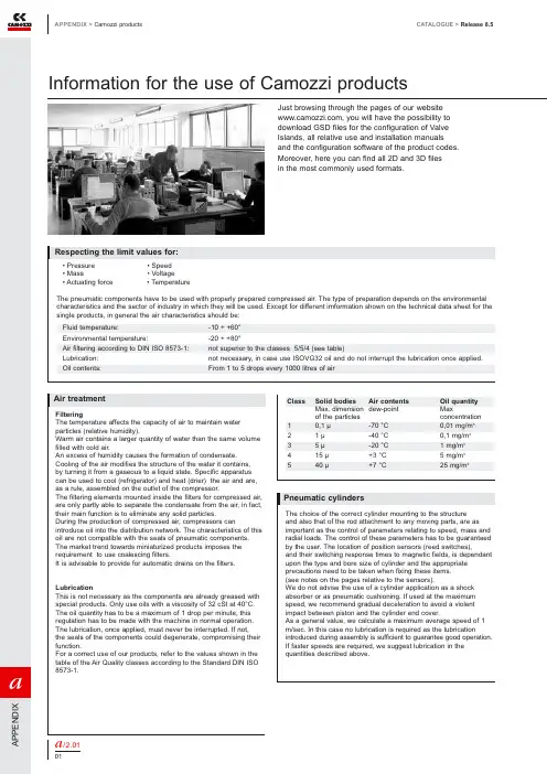
Information for the use of Camozzi productsCATALOGUE >Release 8.5APPENDIX >Camozzi products/2.0101A P P E N D I XJust browsing through the pages of our website , you will have the possibility to download GSD files for the configuration of Valve Islands, all relative use and installation manuals and the configuration software of the product codes.Moreover, here you can find all 2D and 3D files in the most commonly used formats.a/2.0102a A P P E N DI XDouble-acting cylinder, fixed cushionsDouble-acting cylinder, cushionedDouble-acting cylinder, adjustable rear cushionDouble-acting cylinder, adjustable front cushionDouble-acting cylinder, through-rod, fixed cushionsDouble-acting cylinder, through-rod,adjustable front and rear cushion Double-acting cylinder, magneticDouble-acting cylinder, magnetic, fixed cushionsDouble-acting cylinder, magnetic, adjustable cushions in both directionsDouble-acting cylinder, magnetic, adjustable rear cushionDouble-acting cylinder, magnetic, adjustable front cushionDouble-acting cylinder, magnetic, through-rod, fixed cushionsDouble-acting cylinder, magnetic, through-rod, adjustable cushions in both directionsDouble-acting cylinder, magnetic, through-rodMagnetic twin rod cylindersMagnetic twin through-rod cylindersDouble-acting rotary cylinderDouble-acting rotary cylinder, magneticSingle-acting rotary cylinderMagnetic tandem cylinder, two stages, fixed cushionsMagnetic tandem cylinder, three stages, fixed cushionsMagnetic tandem cylinder, four stages, fixed cushionsMagnetic multi-position cylinder, fixed cushionsDouble-acting rodless cylinder, magneticCYLINDERSCYLINDERSSingle-acting cylinder, front springSingle-acting cylinder,non cushionedSingle-acting cylinder, through-rodSingle-acting cylinder, through-rod, adjustable cushionSingle-acting cylinder, magneticSingle-acting cylinder, front spring, adjustable rear cushionSingle-acting cylinder, rear spring, magneticSingle-acting cylinder, magnetic, front springSingle-acting cylinder, through-rodSingle-acting cylinder, through-rod, adjustable rear cushionSingle-acting cylinder, front spring, adjustable rear cushionSingle-acting cylinder, through-rod, adjustable rear cushionHydrocheck, regulated rod thrustHydrocheck, regulated rod return Hydrocheck, regulated rod thrust with stop valveHydrocheck, regulated rod return with stop valveHydrocheck, regulated rod thrust with skip valveHydrocheck, regulated rod return with skip valveHydrocheck, regulated rod thrust with skip and stop valveHydrocheck, regulated rod return with skip and stop valve Double-acting magnetic grippersRod lock deviceSOLENOID VALVESDirectly operated solenoid valve, 2/2 NCCD01CD02CD03CD04CD05CD06CD07CD08CD09CD10CD11CD12CD13CD14CD15CD16CD17CD18CD19CD2TCD3TCD4TCDPPCDSSCS03CS04CS05CS06CS07CS08CS09CS10CS11HI01HI02HI03HI04HI05HI06HI07HI08PNZ1RDLKEV01CATALOGUE >Release 8.5APPENDIX >Camozzi products Pneumatic symbols/2.0301A P P E N D I XSymbol TypeSymbol TypeCS13Symbol TypeSymbol TypeSOLENOID VALVESSOLENOID VALVESDirectly operated solenoid valve, 3/2 NCDirectly operated solenoid valve, 3/2 NC, monostable, with manual overrideDirectly operated solenoid valve, 3/2 NODirectly operated solenoid valve, 3/2 NO, monostable, with manual overrideSolenoid valve, 3/2 NC with quick exhaustDirectly operated solenoid valve, 3/2 NC, bistable, with manual overrideDirectly operated solenoid valve, 3/2 NO, bistable, with manual overrideSolenoid valve, 3/2 NC, monostable, with bistable manual overrideSolenoid valve, 3/2, monostable,solenoid pilot with separate air supply and bistable manual override Solenoid valve, 3/2 NO, monostable, with bistable manual overrideSolenoid valve, 3/2, monostable,solenoid pilot with separate air supply and bistable manual override Solenoid valve, 3/2, bistable, with manual override bistabileSolenoid valve, 3/2, bistable,solenoid pilot with separate air supply and bistable manual overrideSolenoid valve, 3/2 NC, monostable, (pneumatic spring) and bistable manual overrideSolenoid valve, 3/2 NO, monostable, (pneumatic spring) and bistable manual overrideSolenoid valve, 5/2, monostable, with bistable manual overrideSolenoid valve, 5/2, monostable,solenoid pilot with separate air supply and bistable manual overrideSolenoid valve, 5/2, monostable,(pneumatic spring) and manual overrideSolenoid valve, 5/2, monostable,(pneumatic spring) and bistable manual overrideSolenoid valve, 5/2, monostable, solenoid pilot with separate air supply, pneumatic spring and bistable manual override Solenoid valve, 5/2, bistable, with bistable manual overrideSolenoid valve, 5/2, bistable, with manual overrideSolenoid valve, 5/2, bistable,solenoid pilot with separate air supply and bistable manual overrideSolenoid valve, 5/3 CC,with bistable manual overrideSolenoid valve, 5/3, solenoid pilot with separate air supply and bistable manual overrideSolenoid valve, 5/3, solenoid pilot with separate air supply and bistable manual override Solenoid valve, 5/3 CO, with manual overrideSolenoid valve, 5/3 CO,with bistable manual overrideSolenoid valve, 5/3 CO,solenoid pilot with separate air supply and bistable manual overrideSolenoid valve, 5/3 CO,solenoid pilot with separate air supply and bistable manual override Solenoid valve, 5/3 CP , with manual overrideSolenoid valve, 5/3 CP ,with bistable manual overrideSolenoid valve, 5/3 CP , solenoid pilot with separate air supply and bistable manual override Solenoid valve, 5/3 CP , solenoid pilot with separate air supply and bistable manual overrideDouble solenoid valve, 3/2 NC,monostable, with bistable manual overrideDouble solenoid valve, 3/2, monostable, solenoid pilot with separate air supply and bistable manual overrideDouble solenoid valve, 3/2 NO,monostable, with bistable manual overrideDouble solenoid valve, 3/2, monostable, solenoid pilot with separate air supply and bistable manual overrideDouble solenoid valve, 3/2 NC, NO,monostable, with bistable manual overrideDouble solenoid valve, 3/2, monostable, solenoid pilot with separate air supply and bistable manual overrideDirectly operated solenoid valve, 3/2,possible universal use, reversed printed ports 1 and 2 on the bodyIndirectly operated solenoid valve, 2/2 NODirectly operated solenoid valve, 2/2 NC, with linked diaphragmIndirectly operated solenoid valve, 2/2 NCPNEUMATICALLY OPERATED VALVES Pneumatically operated valve,3/2, monostable, mechanical spring Pneumatically operated valve, 3/2, bistableEV05EV06EV07EV08EV09EV10EV11EV12EV13EV14EV15EV16EV17EV18EV19EV20EV21EV22EV23EV24EV25EV26EV48EV47EV46EV43EV42EV45EV44EV41EV40EV39EV38EV37EV36EV35EV30EV31EV32EV33EV34APPENDIX >Camozzi productsCATALOGUE >Release 8.5/2.0302aA P P E N D I XEV04EV03EV29EV28CATALOGUE >Release 8.5APPENDIX >Camozzi productsa /2.0303A P P E N D I XVN01VN02VN03VN04VN05VN06VN07VN08VN09VN10VN11VN12VN13VN14VN15VN16VN17VN18VN19VN20VN21VN22VN23VN24VN25Symbol TypeSymbol TypePNEUMATICALLY OPERATED VALVES MECHANICALLY OPERATED VALVES Pneumatically operated valve, 5/2, preferentialPneumatically operated valve, 5/2, bistablePneumatically operated valve, 5/2, monostable, pneumatic spring Pneumatically operated valve, 5/3 CCPneumatically operated valve, 5/3 COPneumatically operated valve, 5/3 CPPneumatically operated double valve, 3/2, monostablePneumatically operated double valve, 3/2, monostablePneumatically operated double valve, 3/2, monostableMECHANICALLY OPERATED VALVES Mechanically operated valve, plunger actuation, 3/2 NC, monostable, mechanical spring Mechanically operated valve, plunger actuation, 3/2, monostable, mechanical springMechanically operated valve, plunger actuation, 3/2 NO, monostable, mechanical spring Mechanically operated valve,lever/roller actuation, 3/2 NC, monostable,mechanical springMechanically operated valve,lever/roller actuation, 3/2, monostable, mechanical springMechanically operated valve,lever/roller actuation, 3/2 NO, monostabile,mechanical springMechanically operated valve, unidirectional lever actuation, 3/2 NC, monostable, mechanical springMechanically operated valve, unidirectional lever actuation,3/2 monostable, mechanical springMechanically operated valve, plunger actuation, 5/2, monostable, mechanical springMechanically operated valve, plunger actuation, 5/2, monostable, mechanical springMechanically operated valve, lever/rolleractuation, 5/2, monostable, mechanical spring Mechanically operated valve, lever/rolleractuation, 5/2, monostable, mechanical spring Mechanically operated valve,unidirectional lever actuation, 5/2, monostable, mechanical spring Mechanically operated sensor valve, 3/2 NO, monostable, mechanical spring Mechanically operated sensor valve, 3/2 NC, monostable, mechanical spring Mechanically operated sensor valve, plunger actuation, 5/2, monostable, mechanical springMechanically operated sensor valve, plunger actuation, 5/2, bistable Valvola a comando meccanico frontale sensibile 5/2, bistabile Mechanically operated sensor valve, lever/roller actuation, 5/2, bistableMANUALLY OPERATED VALVES Manually operated valve, 3/2, bistableManually operated valve, 3/2, bistable, lockable in two positions Manually operated valve, 3/2, bistableManually operated valve, 3/2 NC, monostable, mechanical spring Manually operated valve, 3/2 NO, monostable, mechanical spring Manually operated valve, 3/2, monostable, mechanical spring Manually operated lever valve, 3/2, bistableManually operated lever valve, 3/2, bistableManually operated lever valve, 3/2 NC, monostable, mechanical spring Manually operated lever valve, 3/2, bistableManually operated lever valve, 3/2, monostable, mechanical spring Pedal operated valve, 3/2 NC, monostable, mechanical spring Manually operated valve, 5/2, bistableManually operated valve, 5/2, monostable, mechanical spring Manually operated lever valve, 5/2, bistableManually operated lever valve, 5/2, bistableManually operated lever valve, 5/2, monostable, mechanical spring Pedal operated valve, 5/2, bistablePedal operated valve, 5/2, monostable bistableManually operated lever valve, 5/3 CC, stableManually operated lever valve, 5/3 CC, monostableManually operated lever valve, 5/3 CO, stableManually operated lever valve, 5/3 CO, stableManually operated lever valve, 5/3 CO, monostableManually operated lever valve, JoystikVP06APPENDIX >Camozzi productsCATALOGUE >Release8.5/2.0304aA P P E N D I XFT01FT02FT03FA01FA02FA03FC01PR01PR02PR03PR04PR05PR06LU0FR01FR02AMP1VMP1CATALOGUE >Release 8.5APPENDIX >Technical information about productsSpring loads cylinders/3.0101A P P E N D I XAPPENDIX >Technical information about productsCATALOGUE >Release8.5a /3.0102aA P P E N D IX* F = spring forceFlow and speed cylindersCATALOGUE >Release 8.5APPENDIX >Technical information about products/3.0201A P P E N D IXAPPENDIX >Technical information about productsCATALOGUE >Release8.5/3.0301aA P P E N D I XOutput forces double-acting cylindersThrust sideValues in NewtonTraction sideValues in NewtonTraction sideValues in Newtona /3.03A P P E N D I Xa P E N D I X Table showing air consumption of double-acting cylindersThrust side Values in NL for each 10 mm of stroke Traction side Values in NL for each 10 mm of stroke/3.04A P P E N D I X Traction sideValues in NL for each 10 mm of strokea P E N D I X Dimensioning guide for Shock Absorbers Series SAa /3.05A P P E N D IX Calculation:a P E N D I X = 600 cycles/h ω= 100 cycles/h To ensure the lifetime of the shock absorber, the movement of the impact bodymust be perpendicular to the shock absorbers axial centre.Note : The maximum allowable eccentricity θ≤ 2,5° (0,044 rad).Perpendicularity of the loadωL o a d7. Vacuum switch6. Solenoid valves5. Vacuum generator4. Vacuum hose3. Mounting elements2. Suction pads1. Calculation of the forcesFlowchart for system design Example of Vacuum calculationa /3.07A P P E N D I XComparison:A comparison of the figures for load cases I and II results, in this example, in a maximum value for FTH =1822 N in load case II,and this value is therefore used for further design calculations.a P E N D I X/3.07A P P E N D I Xa P E N DI XCATALOGUE >Release 8.5APPENDIX >Technical information about productsTechnical information about suction padsWhen designing a vacuum circuit and selecting suitable suction pads it is necessary to follow certain calculations toselect each individual component in a correct way.Listed below is a summary of the most common data to take into consideration./3.0801A P P E N D I XAPPENDIX >Technical information about productsCATALOGUE >Release8.5a /3.0802aA P P E N D I X。
PNOZ_s5_Operat_Man_21397-EN-09

– delayed/instantaneous safety contacts by connecting contact expansion modules or external contactors
Installation
Install base unit without contact expansion module: } Ensure that the plug terminator is inserted at the side of the unit.
For your safeห้องสมุดไป่ตู้y
} Only install and commission the unit if you have read and understood these operating instructions and are familiar with the applicable regulations for health and safety at work and accident prevention. Ensure VDE and local regulations are met, especially those relating to safety.
K3 K1 K4 K2
Interface expansion
unit
S34
Y32
14 24 38 48
Centre: Front view with cover, right: Front view without cover
Grey highlighted area: Applies only with UB = 48 – 240 V AC/DC *Insulation between the non-marked area and the relay contacts: Basic insulation (overvoltage category III), safe separation (overvoltage category II)
PLIZ 安全继电器说明书

PNOZ m1p(ETH) PNOZmulti Modular Safety SystemContents PageChapter 1Introduction1.1Validity of documentation1-11.1.1Retaining the documentation1-11.2Overview of documentation1-21.3Definition of symbols1-3Chapter 2Overview2.1Unit structure2-12.1.1Scope of delivery2-12.1.2Unit features2-12.1.3Chip card2-22.2Front view2-32.2.1PNOZ m1p2-32.2.2PNOZ m1p ETH2-32.2.3Key2-4Chapter 3Safety3.1Intended use3-13.1.1System requirements3-13.2Safety regulations3-23.2.1Use of qualified personnel3-23.2.2Warranty and liability3-23.2.3Disposal3-23.2.4For your safety3-3Chapter 4Function description4.1Unit properties4-14.1.1Integrated protection mechanisms4-14.1.2Operation4-14.1.3Block diagram4-14.1.4Diagnostics4-24.1.5Cascading4-24.1.6Safety mat, muting4-24.1.7Interfaces 4-3Chapter 5Installation5.1General installation guidelines5-15.1.1Dimensions5-25.2Install base unit without expansion module 5-35-45.3Connecting the base unit and expansionmodulesChapter 6Commissioning6.1General wiring guidelines6-16.2Ethernet interfaces (only PNOZ m1p ETH)6-26.2.1RJ45 interfaces ("Ethernet")6-26-26.2.2Requirements of the connection cable andconnector6.2.3Interface configuration6-26.2.4RJ45 connection cable6-36.2.5Process data exchange6-46.3Preparing for operation6-56.3.1Function test during commissioning6-56-56.3.2Commissioning the PNOZmulti safety sys-tem for the first time6.3.2.1Load project from chip card6-56.3.2.2Load project via integrated interface6-66.3.3Download modified project to the PNOZ-6-6multi safety system6.3.3.1Load modified project from chip card6-66.3.3.2Load modified project via integrated inter-6-6face6.3.4Connection6-76.4Connection example6-10 Chapter 7Operation7.1Messages7-17.1.1Display elements for device diagnostics 7-17-27.1.2Display elements for the Ethernet connec-tion (only PNOZ m1p ETH)7.2Reset Ethernet connection settings7-3 Chapter 8Technical details8.1Technical details8-18.2Service life graph of output relays8-58-68.3Maximum capacitive load C (μF) with loadcurrent I (mA) at the semiconductor out-puts8.4Order reference8-71.1Validity of documentationThis documentation is valid for the product PNOZ m1p. It is valid untilnew documentation is published.This operating manual explains the function and operation, describesthe installation and provides guidelines on how to connect the product .1.1.1Retaining the documentationThis documentation is intended for instruction and should be retainedfor future reference.1.2Overview of documentation1 IntroductionThe introduction is designed to familiarise you with the contents, struc-ture and specific order of this manual.2 OverviewThis chapter provides information on the product's most important fea-tures.3 SafetyThis chapter must be read as it contains important information on in-tended use.4 Function DescriptionThis chapter describes the product's mode of operation.5 InstallationThis chapter explains how to install the product.6 CommissioningThis chapter describes the product's commissioning and wiring.7 OperationThis chapter describes how to operate the product and gives tips in thecase of a fault.8 Technical DetailsThis chapter contains the product's technical details and order refer-ence.2.1.1Scope of delivery`Base unit PNOZ m1p`Terminator 779 1102.1.2Unit featuresUsing the product PNOZ m1p:Base units from the PNOZmulti modular safety systemThe product has the following features:`Can be configured in the PNOZmulti Configurator`Positive-guided relay outputs:– 2 safety outputsDepending on the application, up to PL e of EN ISO 13849-1 andup to SIL CL 3 of EN IEC 62061`Semiconductor outputs:– 4 safety outputsDepending on the application, up to PL e of EN ISO 13849-1 andup to SIL CL 3 of EN IEC 62061– 1 auxiliary output` 4 test pulse outputs` 1 cascading input and output;can also be used as a standard output`20 inputs for connecting, for example:–E-STOP pushbuttons–Two-hand buttons–Safety gate limit switches–Reset buttons–Light beam devices–Scanners–Enabling switches–PSEN–Operating mode selector switches–Pressure sensitive mats`Muting function`Connectable:–8 expansion modules on the right– 1 fieldbus module on the left– 4 expansion modules on the left`LED for:–Diagnostics–Supply voltage–Output circuits–Input circuits`Monitors shorts across the inputs through test pulse outputs`Monitors shorts between the safety outputs`Integrated interfaces:–PNOZ m1p: Serial interface RS232–PNOZ m1p ETH: 2 Ethernet interfaces`Plug-in connection terminals:either spring-loaded terminal or screw terminal available as an acces-sory (see order reference)`Coated version:Increased environmental requirements2.1.3Chip cardTo be able to use the product you will need a chip card.Chip cards are available with memories of 8 kByte and 32 kByte. Forlarge-scale projects we recommend the 32 kByte chip card (see Tech-nical Catalogue). Accessories chapter).2.2.3KeyKey:`CHIP card:–Interface chip card`X1:–Cascading inputs and outputs CI and CO,–Test pulse outputs T0 … T3`X2:–Semiconductor outputs O0 (3)–Auxiliary output OA0,–Supply connections`X3:–Relay outputs O4 and O5`X4:–RJ 232 interface / Ethernet interface`X5, X6:–Inputs I0 (I19)`X7:–Power supply`LEDs:–PWR–RUN–DIAG–FAULT–I FAULT–O FAULT3.1Intended useThe modular safety system PNOZmulti is used for the safety-related in-terruption of safety circuits and is designed for use on:`E-STOP equipment`Safety circuits in accordance with VDE0113 Part 1 and EN60204-1CAUTION!Inputs and outputs for standard functions must not be used forsafety-related applications.The coated version of the product PNOZ m1p is suitable for use wherethere are increased environmental requirements (see Technical Details).Intended use includes making the electrical installation EMC-compliant.The product is designed for use in an industrial environment. It is notsuitable for use in a domestic environment, as this can lead to interfer-ence.The following is deemed improper use in particular:`Any component, technical or electrical modification to the product`Use of the product outside the areas described in this manual`Use of the product outside the technical details (see chapter entitled“Technical Details”)3.1.1System requirementsPNOZmulti Configurator: From version:`V1.0.1 (PNOZ m1p)`V6.4.0 (PNOZ m1p ETH)Please contact Pilz if you have an older version.3.2.1Use of qualified personnelThe products may only be assembled, installed, programmed, commis-sioned, operated, maintained and decommissioned by competent per-sons.A competent person is someone who, because of their training, experi-ence and current professional activity, has the specialist knowledge re-quired to test, assess and operate the work equipment, devices,systems, plant and machinery in accordance with the general standardsand guidelines for safety technology.It is the company's responsibility only to employ personnel who:`Are familiar with the basic regulations concerning health and safety /accident prevention`Have read and understood the safety guidelines given in this descrip-tion`Have a good knowledge of the generic and specialist standards ap-plicable to the specific application.3.2.2Warranty and liabilityAll claims to warranty and liability will be rendered invalid if:`The product was used contrary to the purpose for which it is intended`Damage can be attributed to not having followed the guidelines in themanual`Operating personnel are not suitably qualified`Any type of modification has been made (e.g. exchanging compo-nents on the PCB boards, soldering work etc.).3.2.3Disposal`In safety-related applications, please comply with the mission time t Min the safety-related characteristic data.`When decommissioning, please comply with local regulations regard-ing the disposal of electronic devices (e.g. Electrical and ElectronicEquipment Act).3.2.4For your safetyThe unit meets all necessary conditions for safe operation. However,you should always ensure that the following safety requirements aremet:`This operating manual only describes the basic functions of the unit.Information on the expanded functions such as cascading can befound in the online help for the PNOZmulti Configurator and in thePNOZmulti technical catalogue. Only use these functions after youhave read and understood the documentation. All necessary docu-mentation can be found on the PNOZmulti Configurator CD.`Adequate protection must be provided for all inductive consumers.`Do not open the housing or make any unauthorised modifications.`Please make sure you shut down the supply voltage when performingmaintenance work (e.g. exchanging contactors).4.1.7InterfacesThe product PNOZ m1pETH has two Ethernet interfaces, the productPNOZ m1p has one serial interface to`Download the project`Read the diagnostic data`Set virtual inputs for standard functions`Read virtual outputs for standard functions.Information on diagnostics via the interfaces can be found in the SpecialApplications Technical Catalogue.Information on communication via Modbus/TCP can be found in the op-erating instructions "PNOZmulti Modbus".The connection to Ethernet is made via the two 8-pin RJ45 sockets.The Ethernet interface is configured in the PNOZmulti Configurator andis described in the online help for the PNOZmulti Configurator.6.1General wiring guidelinesThe wiring is defined in the circuit diagram in the Configurator. There youcan select the inputs that are to perform a particular safety function andthe outputs that will switch this safety function.Please note:CAUTION!DThe plug-in connection terminals on the relay outputs thatcarry mains voltage should only be connected and disconnectedwhen the voltage is switched off.`Information given in the “Technical details” must be followed.`Outputs:–O0 to O5 are safety outputs–O4 and O5 are relay outputs–O0 to O3 are semiconductor outputs–OA0 is an auxiliary output.`To prevent contact welding, a fuse should be connected before theoutput contacts (see technical details).`Use copper wire that can withstand 75 °C.`Sufficient fuse protection must be provided on all output contactswith inductive loads.`Power for the safety system and input circuits must always be provid-ed from a single power supply. The power supply must meet the reg-ulations for extra low voltages with safe separation.`Two connection terminals are available for each of the supply con-nections 24 V and 0 V (semiconductor outputs), plus A1 and A2 (pow-er supply). This means that the supply voltage can be looped throughseveral connections. The current at each terminal may not exceed 3A.`Test pulse outputs must exclusively be used to test the inputs. Theymust not be used to drive loads.Do not route the test pulse lines together with actuator cables withinan unprotected multicore cable.`Test pulse outputs are also used to supply safety mats that trigger ashort circuit.Test pulses that are used for the safety mat may not be reused for oth-er purposes.The Ethernet connection settings of the base unit can be configured in the PNOZmulti Configurator.You can reset the base unit's Ethernet connection settings to the default settings.Proceed as follows:`Switch off the supply voltage`Remove the chip card`Restart the base unit without the chip card inserted.The Ethernet connection settings are now reset to the default settings.Technical detailsElectrical dataSupply voltage U B DC24 VVoltage tolerance-15 %/+20 %Power consumption at U B DCwithout load8.0 W No. 773100, 7731059.0 W No. 773103, 773104per expansion module 2.50 WResidual ripple DC 5 %Status display LEDTimesSwitch-on delay 5.00 sSimultaneity channel 1/2/3 3 sTwo-hand circuit0.5 sSupply interruption before de-energisation 20 msInputsNumber20U_B > 26.4 V : 15, U_B <= 26.4 V : 20 Max. number of live inputs in the area of max. permittedambient temperature (see "Environmental data")Voltage and current at input, reset and feedback circuit24.0 V, 8.0 mAGalvanic isolation noSignal level at "0"-3 - +5 V DCSignal level at "1"15 - 30 V DCMin. pulse duration18 msPulse suppression0.6 msTest pulse outputsNumber of test pulse outputs 4Voltage and current, 24 V0.5 AOff time during self test 5 msGalvanic isolation noShort circuit-proof yesSemiconductor outputsNumber4Switching capabilityvoltage24 Vcurrent 2 Apower48 WDerating of coated version at an ambient temperature > 50°CVoltage24 V No. 773104, 773105Current 1 A No. 773104, 773105Power24 W No. 773104, 773105Max. capacitive load 1 µFExternal supply voltage24.0 VVoltage tolerance-15 %/+20 %Max. duration of off time during self test300 µsGalvanic isolation yesShort circuit-proof yesSwitch-off delay30 msResidual current at "0"0.5 mASignal level at "1"UB - 0.5 V DC bei 2 ARelay outputsNumber2Utilisation category in accordance with EN 60947-4-1Safety contacts: AC1 at240 V 6.0 A, 1440 VASafety contacts: DC1 at24 V 6.0 A, 144 WUtilisation category in accordance with EN 60947-5-1Safety contacts: AC15 at230 V 3.0 A, 690 WSafety contacts: DC13 at24 V (6 cycles/min) 3.0 A, 72 WDerating of coated version at an ambient temperature> 50 °CSafety contacts: AC1 at 240 V 4 A No. 773104, 773105, 960 W No. 773104, 773105 Safety contacts: DC1 at 24 V 4 A No. 773104, 773105, 96 W No. 773104, 773105 Airgap creepage betweenrelay contacts 3 mmrelay contacts and other safe circuits 5.5 mmExternal contact fuse protection (I K = 1 kA) toEN 60947-5-1Blow-out fuse, quick 6 ABlow-out fuse, slow 6 ACircuit breaker 24 VAC/DC, characteristic B/C 6 ASwitch-off delay50 msAuxiliary outputsNumber1Switching capabilityvoltage24 Vcurrent0.5 Apower12.0 WGalvanic isolation yesShort circuit-proof yesResidual current at "0"0.5 mASignal level at "1"UB - 0.5 V DC bei 0.5 ACascading output as auxiliary outputNumber1Switching capabilityvoltage24 Vcurrent0.2 Apower 4.8 WGalvanic isolation noShort circuit-proof yesResidual current at "0"0.5 mAEnvironmental dataEMC EN 60947-5-1Vibration to EN 60068-2-6Frequency10 - 55 HzAmplitude0.35 mmClimatic suitability EN 60068-2-1, EN 60068-2-30, EN 60068-2-78 Airgap creepage in accordance with EN 60664-1Ambient temperature-25 - 60 °C No. 773104, 7731050 - 60 °C No. 773100, 773103Storage temperature-25 - 70 °CClimatic suitability95 % r. F. No. 773104, 773105Condensation permitted No. 773104, 773105No. stands for order number.Mechanical data Protection typeMounting (e.g. cabinet)IP54Housing IP20Terminals IP20DIN rail Top hat rail 35 x 7.5 EN 50022Recess width27 mm Maximum cable runs per input1.0 km Sum of individual cable runs at the test pulse output 40 km Housing material Housing PPO UL 94 V0FrontABS UL 94 V0Cross section of external conductors with screw terminals Power supply, inputs, auxiliary output, semiconductor out-puts, test pulse outputs, cascading outputs:1 core flexible0.50 - 1.50 mm² , 22 - 14 AWG 2 core, same cross section, flexible:with crimp connectors, without insulating sleeve0.50 - 0.75 mm² , 22 - 20 AWG without crimp connectors or with TWIN crimp connectors 0.50 - 0.75 mm² , 22 - 20 AWG Relay outputs:1 core flexible0.5 - 2.5 mm², 22 - 12 AWG 2 core, same cross section, flexible:with crimp connectors, without insulating sleeve0.50 - 1.25 mm², 22 - 16 AWG without crimp connectors or with TWIN crimp connectors 0.50 - 1.25 mm², 22 - 16 AWG Torque setting with screw terminals0.25 NmCross section of external conductors with spring-loaded terminals: Flexible with/without crimp connectors0.50 - 1.50 mm² , 26 - 14 AWG Spring-loaded terminals: Terminal points per connection 1Stripping length 9 mmDimensions Height 94.0 mm Width 135.0 mm Depth 121.0 mmWeight490 g No. 773100500 g No. 773105520 g No. 773103550 g No. 773104Safety characteristic dataUnit Operating mode EN ISO 13849-1PLEN 954-1CategoryEN IEC 62061SIL CLPFH [1/h]t M [year]LogicPL e (Cat. 4)Cat. 4SIL CL 3 2.13E-1020 PL e (Cat. 4)Cat. 4SIL CL 3 2.38E-1020Requirement on 1-channel relay outputs for Cat. 2 in accordance with EN 954-1: An additional output switches to a safe condition in the event of an error or, if that is impossible, signals a hazardous condition.All the units used within a safety function must be considered when cal-culating the safety characteristic data.The standards current on 2010-10 apply.The PFH value depends on the switching frequency and the load on the relay output. If the service life graphs are not accessible, the stated PFH value can be used irrespective of the switching frequency and the load, as the PFH value already considers the relay's B10d value as well as the failure rates of the other components.CPUPL e (Cat. 4)Cat. 4SIL CL 3 4.90E-0920expansionPL e (Cat. 4)Cat. 4SIL CL 39.20E-0920Input SC inputs single-channel PL d (Cat. 2)Cat. 2SIL CL 2 2.50E-0920SC inputs dual-channelPL e (Cat. 4)Cat. 4SIL CL 3 2.90E-1020SC inputs light beam device PL e (Cat. 4)Cat. 4SIL CL 3 2.50E-1020SC inputs dual-channel pres-sure sensitive mat PL d (Cat. 3)Cat. 3SIL CL 2 1.81E-0920cascading inputsPL e (Cat. 4)Cat. 4SIL CL 3 3.10E-1020Output SC outputs single-channel PL d (Cat. 2)Cat. 3SIL CL 27.00E-0920SC outputsdual-channel PL e (Cat. 4)Cat. 4SIL CL 38.60E-1020cascading outputsPL e (Cat. 4)Cat. 4SIL CL 3 4.91E-1020relay outputs single-channel PL c (Cat. 1)Cat. 2- 2.90E-0820relay outputsdual-channelPL e (Cat. 4)Cat. 4SIL CL 33.00E-1020CAUTION!It is essential to consider the relay's service life graphs. The relay outputs' safety-related characteristic data is only valid if the val-ues in the service life graphs are met.LogicOrder referenceType Features Order no. PNOZ m1p Base unit773 100 PNOZ m1p coated version Base unit773 105 PNOZ m1p ETH Base unit773 103 PNOZ m1p ETH coated version Base unit773 104 Spring-loaded terminals 1 set783 100 Screw terminals 1 set793 10020878-E N -10, 2010-11 P r i n t e d i n G e r m a n y © P i l z G m b H & C o . K G , 2010d u r a N E T p ®, P i l z ®, P I T ®, P M C p r o te g o ®, P M I ®, P N O Z ®, P r i m o ®, P S E N ®, P S S ®, P V I S ®, S af e t y B U S p ®, S a f e t y E Y E ®, S a f e t y N E T p ®, t h e s p i r i t o f s a f e t y ® a r e r eg i s t e r e d a n d p r o t e c t e d t r a d e m a r k s P i l z G m b H & C o . K G i n s o m e c o u n t r i e s . W e w o u l d p o i n t o u t th a t p r o d u c t f e a t u r e s m a y v a r y f r o m t h e d e t ai l s s t a t e d i n t h i s d o c u m e n t , d e p e n d i n g o n t h e s t a t u s a t t h e t i m e o f p u b l i c a t i o n a n d t h e s c o p e t h e e q u i p m e n t . W e a c c e p t n o r e s p o n s i b i l i t y f o r t h e v a l i d i t y , a c c u r a c y a n d e n t i r e t y o f t h e t e x t a n d g r a p h i c s p r e s e n t e d i n t h i s i n f o r m a t i o n . P l e a s e c o n t a c t o u r T e c h n i c a l S u p p o r t i f y o u h a v e a n y q u e s t i o n s .。
PMM人工电源网络商品说明书

The AMN - Artificial Mains Network, also known as LISN - Line Impedance Stabilization Network is the ancillary device intended for repeatable and accurate measurement of the disturbance voltage that an EUT (Equipment Under T est) may inject into the power line or mains.This is obtained by providing well known impedance value and phase response across the frequency range of the test.L1-150M and L1-150M1 are a single-path LISN (Line Impedance Stabilization Network) designed to be easily used for conducted disturbances measurements according to different standards for Automotive and ISM (Industrial, Scientific, Medical) applications.Selecting the standard is as fast as the turn of a rotary switch located on the rear panel.PMM Artificial Mains Networks provide robust and stable m echanical construction, high quality electric components, easy and perfect grounding, solid input and output power connections. They can be used in conjunction with any EMI receiver or spectrum analyzer and offer features required for safe, repeatable and accurate measurements.Multi-standard Single-path LISNProvided Features•Powering the EUT•EUT termination to a standardizedimpedance respect to the reference ground •Coupling the measuring receiver to the disturbance generated by the EUT•Decoupling the measuring receiver from unwanted RF signals from the power lineMain Features•L1-150M: 100 kHz to 200 MHz frequency range •L1-150M1: 10 kHz to 400 MHz frequency range •Multi standard design •150 A max output current •Suitable also for DC lines•Large baseplate for optimal grounding •Robust, compact construction •Screw terminals for safe wiring•Meets the requirements of several standards including CISPR 16-1-2, CISPR 25, ISO 11452-2/4/5,ISO 7637-2, MIL-STD-461F, DO-160, ED-14GProvided by: (800)404-ATECAdvanced Test Equipment Rentals®Frequency range Continuous rated output currentMax. output current @ 45 °C Max. permissible operating voltagesEUT supply frequency range Equivalent circuit RF output connector EUT connectionLine input connection Ground connectionOperating temperature Storage temperature Dimensions (W x H x D)WeightReceiversLISNRFI Filters• 7010/00: EMI receiver 150 kHz to 1 GHz • 7010/01: EMI receiver 9 kHz to 1 GHz • 7010/02: EMI receiver 9 kHz to 30 MHz • 7010/03: EMI receiver 9 kHz to 3 GHz • 9010: EMI receiver 10 Hz to 30 MHz • 9010F: EMI receiver 10 Hz to 30 MHz• 9010/03P: EMI receiver 10 Hz to 300 MHz • 9010/30P: EMI receiver 10 Hz to 3 GHz •9010/60P: EMI receiver 10 Hz to 6 GHz• L2-16B: single phase AMN, 16 A • L3-32: 4 lines, 3-phase AMN, 32 A • L3-64: 4 lines, 3-phase AMN, 63 A• L3-64/690: 4 lines, 3-phase AMN, 63 A • L3-100: 4 lines, 3-phase AMN, 100 A • L3-500: 4 lines, 3-phase AMN, 500 A • L1-500: single phase AMN, 500 A•L2-D: Delta LISN for telecom, 2 A, 150 Ω• FIL-L2-16F: single phase RFI filter, 16 A • FIL-L2-24M: single phase RFI filter, 24 A • FIL-L3-32M: 3-phase+neutral RFI filter, 32 A •FIL-L3-70M: 3-phase+neutral RFI filter, 70 A100 kHz to 200 MHz L1-150M, L1-150M1Multi-standard Single-path LISNOrdering Information:L1-150M - L1-150M1 Artificial NetworkIncludes: Operating Manual, RF Cable, N-BNC adapter, Calibration CertificateOptional accessories:SBRF4: RF switching boxAutomatic (in conjunction with PMM receivers) andmanual switching of up to four single-path AMN. Internal 50 Ohm terminations and switchable 150 kHz high-pass filter. Low insertion loss.Max. operating frequency: 108 MHz.L 1150-F E N -40704 - S p e c i fi c a t i o n s s u b j e c t t o c h a n g e s w i t h o u t p r i o r n o t i c eSPECIFICATIONSRelated Products•Electrical safety and presence of ground protection relays do require the installation of properly rated insulating transformer(s) between mains power line and AMN line inputs.•High mains noise may require the installation of properly rated mains filters to reduce the level of unwanted signals.Sales Office:Via Leonardo da Vinci, 21/2320090 Segrate (Milano) - ITALY Phone: +39 02 2699871Fax: +39 02 26998700E-Mail:**************************Internet: www.narda-sts.itHeadquarter:Via Benessea, 29/B17035 Cisano sul Neva (SV) - ITALY Phone: +39 0182 58641Fax: +39 0182 586400L1-150ML1-150M110 kHz to 400 MHz100 A150 A 600 Vdc 300 Vac DC to 440 Hz (5 μH+0/1 Ω)//50 Ω N female, 50 Ω Screw terminal M10 Screw terminal M10 2x Screw terminal M10-10 to +45 °C -25 to +70 °C 230 x 105 x 410 mm5 kg。
JA71-xxx Blanking Plate Installation Manual

JA71-xxxDzus Blanking PlateInstallation ManualRev. AJupiter Avionics Corporation1959 Kirschner RoadKelowna BCCanada V1Y 4N7Tel: 778-478-2232Toll-Free: 855-478-2232Copyright 2013 Jupiter Avionics Corp.All rights reservedJupiter Avionics Corporation (JAC) permits a single copy of this manual to be printed or downloaded for the express use of an installing agency. Any such electronic or printed copy of this manual must contain the complete text of this copyright notice. Any unauthorized commercial distribution of this manual is strictly prohibited. Except as described above, no part of this manual may be reproduced, copied, transmitted, disseminated, downloaded, or stored in any storage medium for any purpose without the express prior written consent of JAC.RECORD OF REVISIONSRevision Rev DateDescriptionECR A Jan 20132133Table of ContentsSECTION 1 - DESCRIPTION (1)1.1 System Overview (1)1.2 Features Overview (1)1.4 Specifications (1)1.4.1 Mechanical Specifications (1)1.4.2 Product Naming Convention (1)1.4.3 Environmental Specifications (1)SECTION 2 – INSTALLATION (2)2.1Introduction (2)2.2Continued Airworthiness (2)2.3Unpacking and Inspecting Equipment (2)2.3.1Warranty (2)2.4Installation Procedures (2)2.4.1Mechanical Installation (2)2.6 Installation Kit (2)2.7 Installation Drawings (2)Appendix A - Installation Drawings ................................................................................................................................. A1 A1Installation Drawings ....................................................................................................................................... A1 A2Qualification Form ........................................................................................................................................... A1SECTION 1 - DESCRIPTION1.1 System OverviewThe JA71 Dzus Blanking Plate allows the aircraft owner /operator to fill a void in a Dzus rail equipment rack with a compatible color and sized cover plate. The Dzus blanking plate reduces the amount of debris and dust entering the equipment rack.1.2 Features OverviewThe JA71 is painted with a baked-on urethane finish to resist scratches and nicks during use. The JA71 comes in 7 different heights ranging from 1 Dzus hole (JA71-xx1) to 7 Dzus holes (JA71-xx7). The rear side is milled out to accommodate switches or a printed circuit board. The design and color can match existing equipment to present a professional look and feel to the instrument panel.1.4 Specifications1.4.1 Mechanical SpecificationsHeight (Max) Weight (Max) Dzus Fasteners JA71-x01 0.375 in (9.52 mm)0.06 lbs (0.03 kg)TwoJA71-x02 0.750 in (19.05 mm)0.07 lbs (0.03 kg)TwoJA71-x03 1.125 in (28.58 mm)0.11 lbs (0.05 kg)TwoJA71-x04 1.500 in (38.10 mm)0.13 lbs (0.06 kg)TwoJA71-x05 1.875 in (47.62 mm)0.17 lbs (0.08 kg)FourJA71-x06 2.250 in (57.12 mm)0.19 lbs (0.09 kg)FourJA71-x07 2.625 in (66.68 mm)0.21 lbs (0.10 kg)FourAll versions: Depth 0.32 in (8.1 mm) maximumWidth 5.75 in (146.1 mm) maximumMaterial 6061-T6XX aluminum with flat urethane paint finish 1.4.2 Product Naming ConventionJ A71-x x xProduct Number x = Color option x = Custom option x = Height option0 = Black FED-STD-37038 1 = 1 Dzus hole1 = Gray FED-STD-362312 = 2 Dzus hole etc.1.4.3 Environmental SpecificationsThe JA71-xxx Blanking Plate has been qualified to the environmental conditions listed below. Environmental categories for which performance has been qualified are listed in the Environmental Qualification Form in Appendix A of this manual.Shock, Crash Safety 20 g for 11 msVibration Cat SBM, Cat U2FF1DO-160G Env. Cat. XXXB[(SBM)(U2FF1)]XXXXXXXXXXXXXXXXXXSECTION 2 – INSTALLATION2.1 IntroductionThis section contains unpacking and inspection procedures and installation information.2.2 Continued AirworthinessMaintenance of the JA95-001 is on condition only. Scheduled inspection and/or periodic maintenance of this unit is not required.2.3 Unpacking and Inspecting EquipmentUnpack the equipment carefully. Check for shipping damage and report any problems to the relevant carrier. Confirm that the Authorized Release Certificate or Certificate of Conformance is included. Complete the on-line warranty card from the Jupiter Avionics Corporation (JAC) website – .2.3.1 WarrantyAll products manufactured by JAC are warranted to be free of defects in workmanship or performance for 2 years from the date of installation by an approved JAC dealer or agency. This warranty covers the cost of all materials and labour to repair or replace the unit, but does not include the cost of transporting the defective unit to and from JAC or its designated warranty repair centre, or of removing and replacing the defective unit in the aircraft. This warranty does not cover failures due to abuse, misuse, accident, or unauthorized alteration or repairs.Contact JAC for return authorization, and for any questions regarding this warranty and how it applies to your unit(s). JAC is the final arbiter concerning warranty issues.2.4 Installation Procedures2.4.1 Mechanical InstallationThe JA71-xxx can be mounted in any attitude and location. Ensure all Dzus fasteners are secured.2.6 Installation KitN/A2.7 Installation DrawingsThe drawings and documents required for installation can be found in Appendix A of this manual.JA71-xxx Dzus Blanking PlateInstallation ManualAppendix A - Installation DrawingsA1Installation DrawingsDOCUMENTRev JA71-001 Mechanical Installation C JA71-002 Mechanical Installation C JA71-003 Mechanical InstallationC JA71-004 Mechanical Installation C JA71-005 Mechanical Installation C JA71-006 Mechanical Installation C JA71-007 Mechanical InstallationCA2Qualification FormDOCUMENTRev JA71-xxx Environmental Qualification Form AJA71-XXX Dzus Blanking PlateEnvironmental Qualification FormRev. APage 1 of 2Printed using APP-COMCONFIDENTIAL AND PROPRIETARY TO JUPITER AVIONICS CORPORATION.JA71-XXX Dzus Blanking PlateEnvironmental Qualification FormRev. APage 2 of 2Printed using APP-COMCONFIDENTIAL AND PROPRIETARY TO JUPITER AVIONICS CORPORATION.。
桑德森标准产品数据表(数据表16810-A)2020年1月版说明书
Technical DataTechnical DaTa 25-16810-A January 2020 SpecificationSupply Voltage 15 to 30 VdcCable size / Type 0.5mm 2 ~ 2.5mm 2 /FIRETUF, FP200 or MICC Mounting Hole Centres 50 ~ 80mm Allowable Alarm Current25mA Allowable Remote Indicator Current25mAWiring hintsEach terminal is suitable for clamping up to 2 wires. Clamping of 2 wires of very different diameters under one screw is not recommended.DO NOT USE A POWER TERMINAL DRIVER.Suitable for mounting to mounting boxes with 50-80mm fixing centres.EFXN533 DoP044818EN54-7 Point Type Smoke Detectors EFXN525DoP044618EN54-5 Point Type Heat Detectors EFXN524DoP044518EN54-5 Point Type Heat Detectors EFXN526DoP044718EN54-5 Point Type Heat Detectors EFXN632DoP044918EN54-5 Point Type Heat Detectors EN54-7 Point Type Smoke DetectorsFXN922DoP0405122831Detector InstalledDetector RemovedE n d o f L i n e M o n i t o rE n d o f L i n e R e s i s t o rGeneralIf difficulty is experienced when mounting the detector, this may be due to the following:Wiring causing an obstruction - move or shorten wires. Although the base is tolerant to uneven mounting surfaces, a very uneven surface may cause the base to deform when the mounting screws are tightened down - loosen screws to reduce this or slide base to a more flat position.WaRninG: DO NOT USE HIGH VOLTAGE TESTERS WHEN DETECTORS OR CONTROL PANEL ARE CONNECTED TO THE SYSTEM.Zener Diode Switch action eFDB800 (cDB300 & MDB800)eatonEMEA Headquarters Route de la Longeraie 71110 Morges, Switzerland Eaton.euTEL: +44 (0) 1302 321541FAX: +44 (0) 1302 303220******************************************************© 2020 EatonAll Rights ReservedEaton is a registered trademark.All trademarks are property of their respective Eaton Electrical Systems Ltd.Wheatley Hall Road Doncaster DN2 4NBTEL: +44 (0) 1302 303303 FAX: +44 (0) 1302 367155Utilising locking T a bThe Mounting base includes an optional feature to prevent the removal of the detector without the use of a tool.1. Remove the standard fit retaining clip.2. Insert the locking clip which is located at the centre of the base as shown.Mount the detector onto the base as described in Detector Installation (see over) and rotate fully clockwise until it finally clicks.The detector is now locked into position. Remove by utilising a suitable tool (eg a thin screwdriver) into the hole in the detector cover. Gently push the tool into the detector and rotate anti-clockwise.BaseOrder Codes Conventional Photoelectric Smoke Detector - Cooper EFXN520(CDBB300 / FXN520)EFDB800(CDB300 / MDB800) EFXN533 Conventional Heat Detector - Class A2R - Cooper EFXN525Conventional Heat Detector - Class BS - Cooper EFXN524Conventional Heat Detector - Class CS - CooperEFXN526Conventional Photo/Thermal - Class A2S (Heat Performance) - Cooper EFXN632Bi-Wire Programmable Conventional Photoelectric, Photo/Thermal (A2S), Heat Detector (A1R, BS or CS) - JSBEFXN520(CDBB300 / FXN520)FXN922Detector Features (Photoelectric & Photo/Thermal)All Photoelectric and Photo/Thermal detectors, automatically compensate for gradual increases in the scatter signal due to contamination e.g. dust build up.Self-check Features Of The Bi-wire DetectorThe Self-Check feature monitors for the failure of the internal primary alarm circuitry.Under this condition, the detector will still register an alarm condition via the yellow LED. Following such a failure, the yellow LED will remain on following a reset, signaling a fault at the main panel and the detector must be replaced.BiWire detectors, automatically compensate for gradual increases in the scatter signal due to contamination e.g. dust build up. If excessive dust occurs, the yellow LED will show continuously. If this occurs, the maintenance procedure should be conducted.The yellow LED will also light continuously if the detectors optical sensor signal begins to reduce below its normal level (chamber monitoring).In addition, the BiWire range has an isolator that opens if the internal power fails in the detector, giving rise to a zone fault at the main panel.When used with a BiWire compatible panel with Self Check features, the BiWireDetectors range of detectors can be instructed to blink their yellow LED every 2 seconds by a command from the main panel, to aid the search for a break in the zone cabling or an open detector isolator.Detector installationFit detector to mounting base and rotate clockwise until the detector drops into place. Continue to rotate clockwise until the detector clicks into place and no further rotation is possible. If the detectors are required to be locked into position, refer to the ‘UtilisingLocking Tab’ section.Smoke detectors are supplied fitted with dust covers for general protection against airborne contaminates.These must be removed from all detectors before the fire system is commissioned.NB. These dust covers do not provide adequate protection against quantities of dust generated by building workT estingAll detectors must be tested following installation or routine service andmaintenance. It is recommended that these tests are carried out by a competent person. Authorised personnel must be informed that the fire system will betemporarily out of service before commencing testing. To prevent unwanted alarms, ensure that the the panel is in test mode and it may be appropriate to disable some or all of the sounder circuits.. When all tests are complete, restore panel to normal operation and notify authorised personnel that the system is operational.Smoke Detectors:Subject the detector to be tested to a controlled amount of an approved synthetic smoke aerosol via a smoke detector test pole. Suitable products are available for example, from No Climb Products Ltd.Check that the red LED on the detector latches into alarm within 30 seconds. If an optional remote LED is fitted, check that this also lights.Ensure that the control panel activates into alarm.Reset the detector from the control panel unless automatically reset by the panel in test mode.This procedure will test the smoke sensing circuitry of the Photo/Thermal Detector.heat Detectors:Using a heat gun or hair dryer capable of generating temperatures of up to 95°C,direct the heat source towards the heat sensing elements, visible through the side of the outer cover, from a distance of 15 to 30cm. Care should be taken not to allow the plastic surface temperature to exceed 110°C otherwise damage may occur.When the temperature reaches the ‘Alarm Temperature’ (see Specifications above), check that the red LED on the detector latches into alarm. If an optional remote LED is fitted, check that this also lights.Ensure that the control panel activates into alarm.Reset the detector from the control panel unless automatically reset by the panel in test mode.This procedure will test the heat sensing circuitry of the Photo/Thermal Detector.MaintenanceOnly minimal maintenance can be performed on this range of detectors as they do not contain any site serviceable parts. The frequency of maintenance and will depend on the environment towhich the detector is exposed but should be at least annually. Dusty or damp environments will demand more frequent maintenance.Remove the detector from its mounting base.Use a vacuum cleaner to remove dust build up from around the smoke entryapertures of a smoke detector, or from around the heat sensing element of a heat detector.For smoke detectors, visually inspect the insect mesh for blockages. If these can not be cleared by vacuuming, the detector must be replaced.Re-fit detector to its mounting base and test as described above.Detectors that fail the testing procedure must be replaced.EFXN533EFXN525EFXN524EFXN526EFXN632FXN922Operating voltage 15 to 30 Vdc 15 to 30 Vdc 15 to 30 Vdc 15 to 30 Vdc 15 to 30 Vdc 15 to 30 Vdc Standby current (max) 30μA 30μA 30μA 30μA 30μA 80μA Start up current (max 20 sec)340μA N/A N/A N/A 340μA 340μA Alarm current (max)25mA 25mA 25mA 25mA 25mA 25mAAmbient temperature (max)60ºC45ºC60ºC75ºC45ºCOpto Mode 60ºCOpto-Heat Mode 45°CA1R Rate of Rise Mode 45°C BS Fixed Temp Mode 60°C CS Fixed Temp Mode 80°C Ambient temperature (min)-20ºC -20ºC -20ºC -20ºC -20ºC -10ºCAlarm temperature (static)N/A60ºC77ºC90ºC60ºCOpto-Heat Mode 60°CA1R Rate of Rise Mode 60°C BS Fixed Temp Mode 77°C CS Fixed Temp Mode 92°C Heat detector class –as defined by EN54-5:2000N/A A2R BS CS A2S See above Relative humidity (non-condensing)0 to 95%0 to 95%0 to 95%0 to 95%0 to 95%0 to 95%Height (without base)34mm 43mm 43mm 43mm 43mm 43mm Height (with base)47mm 56mm 56mm 56mm 56mm 56mm Diameter 100.5mm 100.5mm 100.5mm 100.5mm 100.5mm 100.5mm Weight 78g 76g 76g 76g 78g 78g Material PC/ABS PC/ABS PC/ABS PC/ABS PC/ABS PC/ABS ColourWhite White White White White White Bi-Wire compatible No No No No No Yes Self check featuresNoNoNoNoNoYes。
MIC2044-1YTS;MIC2044-2YTS;MIC2045-1YTS;MIC2045-2YTS;MIC2044-1YTS TR;中文规格书,Datasheet资料
Typical Application*C4is optional.See"Applications Information."Micrel, Inc. • 1849 Fortune Drive • San Jose, CA 95131 • USA • tel + 1 (408) 944-0800 • fax + 1 (408) 944-0970 • Pin ConfigurationPWRGDEN /FAULT SLEW UVLOINILIMVIN VBIASVINPGREFVOUTVINVOUTVINGNDVOUT MIC2044/MIC204516-Pin TSSOP (TS)Ordering InformationPart NumberStandard Pb-Free Enable Circuit Breaker Package MIC2044-1BTS MIC2044-1YTS Active-High16-Pin TSSOP MIC2044-2BTS MIC2044-2YTS Active-Low16-Pin TSSOP MIC2045-1BTS MIC2045-1YTS Active-High X16-Pin TSSOP MIC2045-2BTS MIC2045-2YTS Active-Low X16-Pin TSSOPPin DescriptionPin Number Pin Name Pin Function1PWRGD Power-Good (Output):Open drain N-Channel device, active high. This pinasserts high when the voltage at PGREF exceeds its threshold.2EN Switch Enable (Input):Gate control pin of the output MOSFET available asan active high (–1) or active low (–2) input signal.3/FAULT Fault Status (Output):Open drain N-Channel device, active low. This pinindicates an overcurrent or thermal shutdown condition. For an overcurrentevent, /FAULT is asserted if the duration of the overcurrent condition lastslonger than 32ms.10GND Ground connection:Tie to analog ground.4SLEW Slew-Rate Control (Input):A capacitor connected between this pin andground will reduce (slow) the output slew-rate. The output turn-on time mustbe less than the nominal flag delay of 32ms in order to avoid nuisancetripping of the /FAULT output since V OUT must be “fully on” (i.e., within200mV of the voltage at the input) before the /FAULT signal delay elapses.The slew-rate limiting capacitor requires a 16V rating or greater, 25V isrecommended. See “Applications Information: Output Slew-Rate Adjust-ment” for further details.6ILIM Current Limit (Input):A resistor (R SET) connected from this pin to groundsets the current limit threshold as I LIMIT = CLF/R SET. CLF is the current limitfactor specified in the “Electrical Characteristics”table. For the MIC2044/45,the continuous output current range is 1A to 6A.5UVLOIN Undervoltage Lockout Adjust (Input):With this pin left open, the UVLOthreshold is internally set to 1.45V. When the switching voltage (V IN) is at orbelow 1.5V, connecting an external resistive divider to this input will lower theUVLO threshold. The total resistance of the divider must be less than 200kΩ.To disable the UVLO, tie this pin to VIN. See “Applications Information” forfurther detail.7,11,13,16VIN Switch Supply (Input):Connected to the drain of the output MOSFET. Therange of input for the switch is 0.8V to 5.5V. These pins must be externallyconnected together to achieve rated performance.9,12,14VOUT Switch (Output):Connected to the source of the output MOSFET. Thesepins must be externally connected together to achieve rated performance.8VBIAS Bias Supply (Input):This input pin supplies power to operate the switch andinternal circuitry. The input range for VBIAS is 1.6V to 5.5V. When switchedvoltage (V IN) is between 1.6V to 5.5V and the use of a single supply isdesired, connect VBIAS to VIN externally.15PGREF Power-Good Threshold (Input):Analog reference used to specify thePWRGD threshold. When the voltage at this pin exceeds its threshold, V TH,PWRGD is asserted high. An external resistive divider network is used todetermine the output voltage level at which V TH is exceeded. See the“Functional Description”for further detail. When the PWRGD signal is notutilized, this input should be tied to VOUT.Absolute Maximum Ratings (Note 1)V IN and V BIAS (6V)/FAULT, PWRGD Output Voltage (6V)/FAULT, PWRGD Output Current..............................25mA ESD Rating, Note 3Human Body Model...................................................2kV Machine Model........................................................200V Operating Ratings (Note 2)Supply VoltageV IN...............................................................0.8V to 5.5V V BIAS...........................................................1.6V to 5.5V Continuous Output Current...................................1A to 6A Ambient Temperature (T A)...........................–40°C to 85°C Package Thermal Resistance (Rθ(J-A))TSSOP................................................................85°C/WElectrical Characteristics (Note 4)V IN = V BIAS = 5V, T A = 25°C unless specified otherwise. Bold indicates –40°C to +85°C.Symbol Parameter Condition Min Typ Max Units V IN Switch Input Voltage V IN≤ V BIAS0.8 5.5V V BIAS Bias Supply Voltage 1.6 5.5V I BIAS V BIAS Supply Current - Switch OFF No load0.15µAV BIAS Supply Current - Switch ON No load300400µANote 5V EN Enable Input Voltage V IL(max) 2.4 1.5VV IH(min) 3.5 2.5V V ENHYST Enable Input Threshold Hysteresis100mV I EN Enable Input Current V EN = 0V to 5.5V–1.011µA R DS(ON)Switch Resistance V IN = V BIAS = 3V, 5V2030mΩI OUT = 500mAI LEAK Output Leakage Current Output off10µA CLF Current Limit Factor V IN = 3V, 5V, 0.5V ≤ V OUT < 0.5V IN300380460A•ΩNote 61A ≤ I OUT≤ 6AV TH PGREF Threshold V IN = V BIAS = 1.6V to 5.5V215230245mV V LATCH Output Reset Threshold V IN = 0.8V to 5.5V V IN–.0.2VV OUT rising (MIC2045)I LATCH Latched Output Off Current Output latched off (MIC2045)135mA V OL Output Low Voltage I OL (/FAULT) = 15mA0.4V (/FAULT, PWRGD)I OL (PWRGD) = 5mAI OFF/FAULT, PWRGD Off Current V FAULT = V PWRGD = 5V1µA V UV Undervoltage Lockout Threshold V IN rising 1.30 1.45 1.58VV IN falling 1.20 1.35 1.50V V UVHYST Undervoltage Lockout100mV Threshold HysteresisV UVINTH UVLO Adjust Pin Threshold Voltage V IN rising200230260mVV IN falling185215245mV V UVINHYST UVLO Adjust Pin Threshold Hysteresis15mV Overtemperature Threshold T J increasing140°CT J decreasing120°CSymbol ParameterConditionMin Typ Max Units t FLAG Flag Response Delay V IN = V BIAS = 3V, 5V 253240ms t ON Output Turn-on Delay R LOAD = 10Ω, C LOAD = 1µF 0.751 1.25ms t R Output Turn-on Rise Time R LOAD = 10Ω, C LOAD = 1µF 1.52.53.5ms t OFF Output Turn-off Delay R LOAD = 10Ω, C LOAD = 1µF 15µs t FOutput Turn-off Fall TimeR LOAD = 10Ω, C LOAD = 1µF24µsNote 1.Exceeding the absolute maximum rating may damage the device.Note 2.The device is not guaranteed to function outside its operating rating.Note 3.Devices are ESD sensitive. Handling precautions recommended. Human body model:1.5k Ω in series with 100pF.Note 4.Specification for packaged product only.Note 5.OFF is V EN < 1.0V for MIC2044/MIC2045–1 and V EN > 4.0V for MIC2044/MIC2045 –2. ON is V EN > 4.0V for MIC2044/MIC2045–1 and V EN < 1.0V for MIC2044/MIC2045 –2.Note 6.The current limit is determined as follows:I LIM = CLF/R SET .Timing DiagramsV ENV OUTV ENV OUTFigure 1. Turn-On/Turn-Off DelayV ENV OUTI OUT/FAULTFigure 2. Overcurrent Fault Response — MIC2044-2Test CircuitVS U P P L Y C U R R E N T (µA )TEMPERATURE (°C)Supply CurrentV E N (V )TEMPERATURE (°C)Enable Input Threshold(Rising)V E N (V )TEMPERATURE (°C)Enable Input Threshold(Falling)O U T P U T L E A K A G E (n A )TEMPERATURE (°C)Output Leakage CurrentO N R E S I S T A N C E (m Ω)TEMPERATURE (°C)ON ResistanceT F L A G (m s )TEMPERATURE (°C)Flag Response DelayT U R N O N D E L A Y (µs )TEMPERATURE (°C)Turn On Delayvs. TemperatureI R (m A )V OUT–V BIAS (V)V BIAS Reverse Current FlowTypical CharacteristicsU V L O T H R E S H O L D (V )TEMPERATURE (°C)UVLO ThresholdU V L O I N T H R E S H O L D (m V )TEMPERATURE (°C)UVLO Adjust Pin ThresholdS L E W P I N V O L T A G E (V )TEMPERATURE (°C)SLEW Voltage V T H (m V )TEMPERATURE (°C)Power-Good ReferenceThresholdFunctional CharacteristicsV IN =V BIAS =5.0VR LOAD =1.65V C LOAD =47m F R SET =100WTIME (500m s/div.)V IN = V BIAS = 5.0VR LOAD = 1.8ΩC LOAD = 47µF R SET = 220ΩLatched OutputTIME (5ms/div.)V IN = V BIAS = 5.0VR LOAD toggles from 2Ω to OPENC LOAD = 47µF R SET = 220Ω4.82VLatched Output ResetMIC2045TIME (50ms/div.)V IN ramps 0V to 1.8VR LOAD = 5ΩC LOAD = 47µF R SET = 220ΩUVLO ResponseTIME (2.5ms/div.)1.45VV IN = V BIAS = 5.0VR LOAD = 1.2ΩC LOAD = 47µF R SET = 100ΩCurrent Limit ResponseTIME (5ms/div.)Functional Characteristics (continued)V IN = 5.0VR LOAD =5ΩC LOAD =47µFC SLEW =0.033µFR SET =220ΩTIME (2.5ms/div.)V IN = V BIAS 5.0VR LOAD =2ΩC LOAD =47µFR SET =220ΩTIME (100ms/div.)Functional Diagram分销商库存信息:MICRELMIC2044-1YTS MIC2044-2YTS MIC2045-1YTS MIC2045-2YTS MIC2044-1YTS TR MIC2044-2YTS TR MIC2045-1YTS TR MIC2045-2YTS TR MIC2044-1BTS MIC2044-1BTS TR MIC2044-2BTS MIC2044-2BTS TR MIC2045-1BTS MIC2045-1BTS TR MIC2045-2BTS MIC2045-2BTS TR。
PNZ102资料
1
PNZ102
PC Ta
200 20
IC VCE
30 µA 25 µA 20 Ta = 25°C 16 1 000 lx
ICE(L) VCE
500 lx Ta = 25°C T = 2 856 K
Collector power dissipation PC (mW)
102
Rise time tr (µs)
60
60
RL = 1 k Ω 10 500 Ω 100 Ω 1
40
40
20
20
0 200
400
600
800
1 00
10
30
10−1 −1 10
1
10
102
Wavelength λ (nm)
Half-power angle θ (°)
Photocurrent ICE(L) (mA)
100 lx L = 50 lx
0 −20
0
20
40
60
80
100
0
0
10
20
30
0
1
10
20
30
Ambient temperature Ta (°C)
Collector-emitter voltage VCE (V)
Collector-emitter voltage VCE (V)
ICE(L) L
Spectral sensitivity characteristics
100 Ta = 25°C 80 80 100
Directivity characteristics
177133 Operator Czech
Provozní Příručka zařizení ...... postup Krok Za KrokemBezpečnost Celkový popis stroje Ovládací panel Zapnutí a přihlášení Změna produktul Tisk produktu Doplňování materiálu Výměna dílů Chybové zprávyADOVER TECHNOLOGIES COMPANYCopyright ©2002 DEK Printing Machines Ltd. All Rights Reserved.Prírucka - 4.kvetna 2002PT. NO. 177133BEZPEČNOST VAROVNÉ A UPOZORNUJÍCÍ POKYNYAbychom mohli zajistit, aby provozní podmínky pro sítotiskové zařízení byly v každou dobu zajišteny, musí se všechny osoby řídit bezpecnostními opatřeními popsanými v této přírucce a všeobecne uznávanými bezpecnostními postupy. Poznámka POZOR upozornuje obslužný a údržbový personál na možná nebezpecí, která mohou vést k újme na zdraví, ke zranení nebo rovnež ke smrti. Tato nebezpecí zpusobují samotné soucásti zařízení, nebo vznikají behem provozu zařízení. Tabulka níže ukazuje příklady varovných znacek, které se na zarízení nacházejí. Na zarízení se muže nacházet kombinovaná varovne upozornující znacka podle níže zobrazeného typu. Tato znacka znamená, že uživatel by si mel precíst patricnou kapitolu technické prírucky, dríve než zacne na zařízení pracovat.VAROVNÉ ZNACKYSymbol Definice Varování: Vykřicník Všeobecná varovná poznámka, která slouží pro všechna nebezpecí, která nejsou oznacena speciální varovnou znackou. Varování: Ostré Hrany Nebezpecí poranení o ostrou hranu v blízkosti varovné znacky. Při práci v této oblasti bud’te opatrní. Varování: Dráždivé látky Existují zde látky, které pri prvním, opakovaném nebo dlouhodobém kontaktu s pokožkou nebo sliznicí mohou vést k vznícení. Varování: Hořlavý materiál Nacházejí se zde horlavé látky. Zabrante vzniku vysokých teplot, styku se zápalným zdrojem a zabrante statickému výboji. Pracujte na dobře vetraném míste. Varování: Pohyblivé cásti V blízkosti varovné znacky se nacházejí cásti, které se pohybují. Tyto cásti mohou zpusobit zranení. Kryty zařízení nesmí být odstranovány. Varování: Záření Nebezpecí poškození ocí laserovým paprskem v blízkosti znacky. Nedívejte se do zdroje svetla nebo do přímého odrazu od nekteré plochy. Varování: Vysoký tlak Je zde vysoký tlak, který muže vést ke zranení. Systém neotvírejte do přímého okolního prostředí. Varování: Vysoké napetí Nachází se zde vysoké elektrické napetí, které muže vést k poranení nebo ke smrti. Nesundávejte kryty ze zařízení a nedeaktivujte ochranná zařízení.Poznámka UPOZORNENÍ, opatrne upozornuje personál na to, že zařízení muže být poškozeno, obzvlášte pak, pokud se odchýlíte od pevne stanoveného postupu. Na nebezpecí pro osoby taková znacka neupozornuje. Jako příklad upozornovací poznámky je:UPOZORNENÍ Poškození kamery. Na zvedacím stole za zadní kolejnicí nesmí zustat ležet žádné nepotrebné nářadí. Pokud by se na zvedacím stole mimo oblast nanášení na desku nacházel nejaký objekt, m u ž e u n e j d o j í t k e k o n ta k t u s k a m e r o u , k d y ž z v e d a c í s t u l vyjede do polohy tisku.1BEZPEČNOSTNÁHLED ZARÍZENÍM OBSAHTato přírucka by mela být používána odpovídajícím vyškoleným personálem. Obsahuje krátký přehled všeobecnými provozními podmínkami zařízení. Další informace o vybavení zařízení mužete v každém případe získat v programovací a údržbové přírucce.109Pozice 118Oznacení Monitor /IR přijímac Trojbarevné signalizacní svetlo Systémové tlacítko - přední strana Tlacítko E-stop (STOP) - přední strana Kontrolní tlacítka Sít’ový vypínac Paste Roll Lamp (optional) Tlacítko E-stop (STOP) - zadní strana Systémové tlacítko - zadní strana IR - klávesnice (myš)2 324 5 6 7 8 9310POZNÁMKA Zapnuté zařízení bude uvedeno do cekacího stavu, pokud bylo stisknuto nekteré cervené tlacítko E-stop (STOP).45 15762NÁHLED ZARÍZENÍMOBSLUHA ZARÍZENÍ - MÍSTA PRIPOJENÍ STAVOVÁ STRÁNKAInformace zobrazené na hlavní obrazovce leží na stavové stránce. Existují dve ruzné verze stavové stránky.Type 28 7 1Type 16 271623543Pozice 15 4Oznacení Okno parametru procesu Okno parametru zarízení Lišta hlášek Lišta menu Okno informací z kamery Okno varovných hlášek Okno stavu sítotisku 8 Titulní okno sítotisku2 3 4 5 6 7 8Pozice 1 2 3 4 5 6 7Oznacení Titulní okno sítotisku Okno parametru procesu Lišta hlášek Lišta menu Okno informací z kamery Okno varovných hlášek Okno stavu sítotiskuPOZNÁMKA Pro výber z menu je třeba najet ukazatelem myši s přepínacem KlávesniceMyš na příslušnou spínací plošku menu a kliknout na klávesnici levým tlacítkem myši. Výber je také možné provést pomocí funkcních kláves F1 F8 z klávesnice (císla F kláves jsou zobrazena v lište menu).3OBSLUHA ZARÍZENÍ - MÍSTA PRIPOJENÍOBSLUHA ZARÍZENÍ - MÍSTA PRIPOJENÍ Okno informací z kameryVelikost okna informací z kamery muže být na stavové stránce zmenena pomocí symbolu Zoom In případne Zoom Out.4OBSLUHA ZARÍZENÍ - MÍSTA PRIPOJENÍOBSLUHA ZARÍZENÍ - MÍSTA PRIPOJENÍ SIGNÁLNÍ SVETLOSignální svetlo zobrazuje provozní stav zarízení:BarvaProvozní stav Zařízení není v provozu Systém je vypnut Je zobrazena chybová hláška. Zásobník na pastu je témer prázdný ProFlow je dole Papírový válec je prázdný Nádržka na cistící prostredek je prázdná Cistící kazeta ve "Vortex" vycerpána Zařízení se nenachází v provozním stavu Inicializace zarízení Zarízení je v prípravném stavu Zarízení je v údržbovém stavu Zařízení vyžaduje pozornost obsluhy Zásobník na pastu je témer prázdný ProFlow je dole Papírový válec je prázdný Nádržka na cistící prostredek je prázdná Cistící kazeta ve "Vortex" vycerpána Zařízení je v provozu Zarízení ceká v stavu bdelostiPOZNÁMKA Indikace signálního majáku-"Paste cartridge low"(kazeta s pastou je prázdná);"Paper roll empty"(nedostatek cistícího papíru);"Solvent tank empty"(nedostatek cistícího roztoku);"Vortex cleaning cassette expired"(cistící kazeta ve "Vortex" vycerpána),záleží na nastavení v menu "Set preferences".Menu "Set preferences" by nemelo být prístupné pro operátory.5OBSLUHA ZARÍZENÍ - MÍSTA PRIPOJENÍZAPNUTÍ A PRIHLÁŠENÍ1. Sítový vypínac přepnout na ON. 4. Stisknete Load (nahrát, F1).Load Rebuild List Left Right Up Down Exit5. Chcete-li stisknete Systémové tlacítko2. Chcete-li nahrát program, stisknout Load Data (Funkcní Tlacítko, F2 na klávesnici).Load Data DiagnostZobrazí se seznam všech produktových souboru uložených v zařízení:265TEST1 ANDY H CALIBRA DEFAULT DEK04 DEK06Zvolený soubor bude nyní na zvoleném typu stavové stránky zobrazen s následující lištou menu:Load Data FileOpen Cover Paste Load Clean ScreenRunAdjustSetupMonitorMaint.265TEST1SearchTrainingProduct ID6. Stisknout tlacítko Monitor (F7)Run Open Cover Paste Load Clean Screen Adjust Setup Monitor Maint.3. Pomocí Left (Vlevo, F4), Right (Vpravo, F5), Up (Nahoru, F6) a Down (Dolu, F7) oznacte požadovaný soubor.Load Rebuild List Left Right Up Down Exit6ZAPNUTÍ A PRIHLÁŠENÍZAPNUTÍ A PRIHLÁŠENÍ7. Stisknout tlacítko Log On (F1)Log On Clear Batch Batch Limit Perform Display Event Display System Disable ExitBude otevřeno okno Operator Log On (Prihlášení Obsluhy):Operator Log On Enter Operator ID :Pomocí klávesnice zadá obsluhující své jméno a stiskne Enter. 8. Stisknout tlacítko Exit (konec, F8).Log Off Clear Batch Batch Limit Perform Display Event Display System Disable Exit7ZAPNUTÍ A PRIHLÁŠENÍZMENA PRODUKTU NOVÝ PRODUKT1. Stisknete Setup (F6).Mode Run Open Cover Paste Load Clean Screen Adjust Setup Monitor Maint.5. Stisknout Change Screen (Výmena šablony, F5).Load Data Edit Data Setup Squeegee Change Screen Change Tooling Change Language ExitObjeví se hláška „Open cover and remove screen" („Otevrít Kryt, Vyjmout šablonu"). 6. Otevrete kryt zarízení / stínítko sklopte. 2. Stisknete Load Data (Nahrát Soubor, F2).Mode Load Data Edit Data Setup Squeegee Change Screen Change Tooling Change Language ExitBude zobrazen seznam všech souboru produktu uložených v zarízení:265TEST1 ANDY H CALIBRA DEFAULT DEK04 DEK06Load Data File7.Upevnení šablony prepnete na OFF (prepínac prepnout nahoru) (jen pri pevne nastavené šírce kolejí pro šablonu).265TEST1SearchTrainingProduct ID3. Pomocí Left (Vlevo, F4), Right (Vpravo, F5), Up (Nahoru, F6) a Down (Dolu, F7).Load Rebuild List Left Right Up Down Exit8. Vyjmout šablonu.4. Stisknete Load (Nahrát, F1).Load Rebuild List Left Right Up Down ExitZvolený soubor bude nyní zobrazen na stavové stránce. 8ZMENA PRODUKTUZMENA PRODUKTU9. Spodní kryt zvednout / stínítko zavrít. 13. Otevrít kryt zarízení / stínítko sklopit.10. Stisknout Systémové tlacítko.VAROVÁNÍ PRÍTLAKOVÉ LIŠTY DESKY. ABY JSTE ZABRÁNILI ZRANENÍ, PRI PRÁCI V OBLASTI PODEPÍRÁNÍ, POSTUPUJTE VELMI OBEZRETNE. NOŽOVÉ LIŠTY NA PREDNÍ A ZADNÍ PRÍTLAKOVÉ LIŠTE JSOU VELMI OSTRÉ. POZNÁMKA DEK doporucuje, aby obsluha vymenovala pouze magnetické podperné válecky. U jiného typu podpery musí být prípadne zmenen konfiguracní soubor.. UPOZORNENÍ P O š K O ZE N Í K A M E RY. N a zv e da c í m st o l e z a za d n í k ol e j ni c í nesmí zustat ležet žádné nepotrebné náradí. Pokud by se na zvedacím stole mimo oblast nanášení na desku nacházel ne jaký obj ekt, m uže u nej d ojít ke kontaktu s k amerou , když zvedací stul vyjede do polohy tisku.Change Language Exit11. Stisknout Change Tooling (Vymenit Náradí, F6).Mode Load Data Edit Data Setup Squeegee Change Screen Change Tooling14. Podpery desky nastavit odpovídajícím zpusobem k vyrábenému produktu.12. Stisknout Open Cover (Otevrít Kryt, F2).Adjust Open Cover Home Cleaner Board Stop Full Width Load Width Print Height Exit9ZMENA PRODUKTUNásledující tabulka obsahuje chybová hlášení , které se mohou objevit behem normálního provozu tisku, jejich možné príciny a opatrení pro jejich odstranení. Seznam se všemi chybovými hláškami zarízení získáte v prírucce Programování a údržba. Uživatelská prírucka.。
- 1、下载文档前请自行甄别文档内容的完整性,平台不提供额外的编辑、内容补充、找答案等附加服务。
- 2、"仅部分预览"的文档,不可在线预览部分如存在完整性等问题,可反馈申请退款(可完整预览的文档不适用该条件!)。
- 3、如文档侵犯您的权益,请联系客服反馈,我们会尽快为您处理(人工客服工作时间:9:00-18:30)。
Wiring
The wiring is defined in the circuit diagram in the Configurator. There you can select the inputs that are to perform a particular safety function and the outputs that will switch this safety function. Please note: ` Information given in the "Technical
` Semiconductor outputs: – 2 safety outputs in accordance with EN 954-1, Cat. 4 or 4 safety outputs in accordance with EN 954-1, Cat. 3 – 1 auxiliary output
= =
Power
Input
O4 O5
Cascading
Test pulse output
24 V 0 V
CI+ CI- CO+CO- T0 T1 T2 T3 O0 O1 O2 O3 OA0 24 V 0 V
14 24
RS 232
Interface expansion
module
Pilz GmbH & Co. KG, Sichere Automation, Felix-Wankel-Straße 2, 73760 Ostfildern, Germany Telephone: +49 711 3409-0, Telefax: +49 711 3409-133, E-Mail: pilz.gmbh@pilz.de
Where test pulses are used for the safety mat, they may not be reused for other purposes. Safety mats are supported from Version 4.3 of the base unit.
NSG-D-2-361-2007-09
Products
Base units PNOZ m1p coated version
Block diagram
Interface chip card
Interface diagnostic
module
A1 A2 I0 I1 I2 I3 I4 I5 I6 I7 I8 I9 I10 I11 I12 I13 I14 I15 I16 I17 I18 I19 13 23
base unit. The base unit has 2 microcontrollers that monitor each other. They evaluate the input circuits on the base unit and expansion modules and switch the outputs on the base unit and expansion modules accordingly.
` 4 test pulse outputs ` 1 cascading input and output
can also be used as a standard output ` 20 inputs for connecting: – E-STOP pushbutton – Two-hand button – Safety gate limit switch – Reset button – Light beam devices – Scanner – Enable switch – PSEN – Operating mode selector switch – Safety mats ` Muting function ` Connectable: – 8 expansion modules on the
The online help on the PNOZmulti Configurator contains descriptions of the operating modes and all the functions of the PNOZmulti safety system, plus connection examples.
tive in the case of a component failure. ` The relay contacts meet the requirements for safe separation through increased insulation compared with all other circuits in the safety system. ` The safety outputs are tested periodically using a disconnection test.
Safety featБайду номын сангаасres
The relay conforms to the following safety criteria: ` The circuit is redundant with built-in
self-monitoring. ` The safety function remains effec-
` Can be configured in the PNOZmulti Configurator
` Positive-guided relay outputs: – 1 safety output in accordance with EN 954-1, Cat. 4 or 2 safety outputs in accordance with EN 954-1, Cat. 2
VDE 0113 Part 1 and EN 60204-1
Pilz GmbH & Co. KG, Sichere Automation, Felix-Wankel-Straße 2, 73760 Ostfildern, Germany Telephone: +49 711 3409-0, Telefax: +49 711 3409-133, E-Mail: pilz.gmbh@pilz.de
Chip cards are available with memories of 8 kByte and 32 kByte. For largescale projects we recommend the 32 kByte chip card (see chapter containing the order references). The chip card with a memory of 32 kByte can only be used from PNOZ m1p Version 2.0.
NSG-D-2-361-2007-09
-2
Products
Base units PNOZ m1p coated version
Function description
The function of the inputs and outputs on the safety system depends on the safety circuit created using the PNOZmulti Configurator. A chip card is used to download the safety circuit to the
Products
Base units PNOZ m1p coated version
Unit features
Chip card
Base units from the PNOZmulti modular safety system Approvals
PNOZ m1p coated version
Unit description
The PNOZmulti modular safety system
is used for the safety-related interrup-
tion of safety circuits and is designed
for use on: ` Emergency stop equipment ` Safety circuits in accordance with
right – 1 fieldbus module on the left – 4 expansion modules on the left ` LED for: – Diagnostics – Supply voltage – Output circuits – Input circuits ` Test pulse outputs used to detect shorts across the inputs ` Monitoring of shorts between the safety outputs ` Plug-in connection terminals (either cage clamp terminal or screw terminal)
details" must be followed. ` Outputs:
– O0 to O5 are safety outputs. – O4 and O5 are relay outputs – O0 to O3 are semiconductor out-
puts – OA0 is an auxiliary output. ` To prevent contact welding, a fuse should be connected before the output contacts (see technical details). ` Use copper wire that can withstand 75 °C. ` Sufficient fuse protection must be provided on all output contacts with inductive loads. ` Power for the safety system and input circuits must always be provided from a single power supply. The power supply must meet the regulations for extra low voltages with safe separation. ` Two connection terminals are available for each of the supply connections 24 V and 0 V (semiconductor outputs), plus A1 and A2 (power supply). This means that the supply voltage can be looped through several connections. The current at each terminal may not exceed 9 A. ` Test pulse outputs must exclusively be used to test the inputs. They must not be used to drive loads. Do not route the test pulse lines together with actuator cables within an unprotected multicore cable. ` Test pulse outputs are also used to supply safety mats that trigger a short circuit.