3FL24-100中文资料
FM24系列中文资料
引脚说明
串行时钟信号引脚(SCL):在 SCL 输入时钟信号的上升 沿将数据送入 EEPROM 器件,并在时钟的下降沿将数 据读出。
串行数据输入/输出引脚(SDA):SDA 引脚可实现双 向串行数据传输。该引脚为开漏输出,可与其它多个 开漏输出器件或开集电极器件线或连接。
器件/页 地址脚(A2,A1,A0):A2、A1 和 A0 引脚 为 FM24C02 的硬件连接的器件地址输入引脚。在一 个总线上最多可寻址八个 2K 器件。(器件寻址详见器 件寻址章节内容) 。
FM24C08
FM24C08A
全地址(4K)
正常读写 正常读写
全地址(8K)
FM24C16 高半区(8K)
存储器结构
FM24C02,2K 串行电可擦除存储器:内部分为 32 页, FM24C08(A),8K 串行电可擦除存储器:内部分为 64
每页 8 字节,以 8 位地址寻址。
页,每页 16 字节,以 10 位地址寻址。
SCL WP VCC GND NC
引脚功能
器件地址输入 串行数据输入输出 串行时钟输入 写保护 电源 地 不连接
FM24C02/04/08(A)/16 两线制串行 EEPROM
版本 2.2
技术手册
3
图 1.结构框图
FM24C02/04/08(A)/16 两线制串行 EEPROM
版本 2.2
技术手册
版本 2.2
技术手册
6
交流参数
推荐参数的适用工作条件:TA = -40°C ~ +85°C,VCC = +2.2V ~ +5.5V,CL = 1 TTL Gate and 100 pF(除非 另有说明)。测试条件参见“注 2”。
S3C2410中文手册第1章_产品综述
UART................................................................................................................................................ 4 DMA控制器 .....................................................................................................................................5 A/D转换和触摸屏接口 ...................................................................................................................5 LCD控制器STN LCD显示特性 ......................................................................................................5 TFT彩色显示屏 ............................................................................................................................... 5 看门狗定时器.................................................................................................................................. 5 IIC总线接口 ....................................................................................................................................6 IIS总线接口 .....................................................................................................................................6 USB主设备 ......................................................................................................................................6 SD主机接口 ..................................................................................................................................... 6 SPI接口 ............................................................................................................................................ 6 工作电压.......................................................................................................................................... 7 操作频率.......................................................................................................................................... 7 封装.................................................................................................................................................. 7 1.2 内部结构图....................................................................................................................................8 表 1-1 272-FBGA 引脚分配及顺序..........................................................................................9 表 1-2 272-FBGA封装的引脚分配..........................................................................................12 信号描述........................................................................................................................................ 21 表 1-3 S3C2410A信号描述.........................................................................................................21 表 1-4 S3C2410A 专用寄存器...................................................................................................25
15FL24-24W-M中文资料
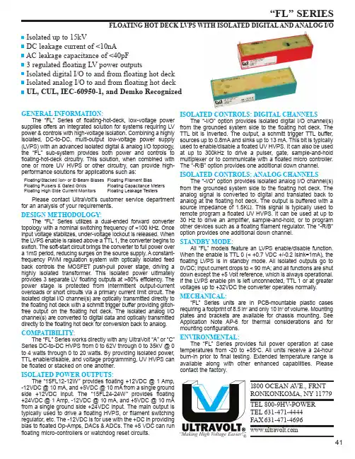
1800 OCEAN A VE., FRNTRONKONKOMA, NY 11779TEL 800-9HV-POWER TEL 631-471-4444FAX 631-471-4696“Making High Voltage Easier!”®Isolated up to 15kVDC leakage current of <10nA AC leakage capacitance of <40pF 3 regulated floating LV power outputsIsolated digital I/O to and from floating hot deck Isolated analog I/O to and from floating hot deck UL, CUL, IEC-60950-1, and Demko RecognizedGENERAL INFORMATION:The “FL” Series of floating-hot-deck, low-voltage power supplies offers an integrated solution for systems requiring LV power & controls with high-voltage isolation. Combining a highly isolated, DC-to-DC, multi-output low-voltage power supply (LVPS) with an advanced isolated digital & analog I/O topology,the “FL” sub-system provides both power and controls to floating-hot-deck circuitry. This solution, when combined with one or more UV HVPS or other circuitry, can provide high-performance solutions for applications such as:Floating/Stacked Ion- or E-Beam Biases Floating Filament Bias Floating Pulsers & Gated Grids Floating Capacitance Meters Floating High Side Current Monitors Floating Leakage TestersPlease contact UltraVolt's customer service department for an analysis of your requirements.DESIGN METHODOLOGY:The “FL” Series utilizes a dual-ended forward converter topology with a nominal switching frequency of <100 kHz. Once input voltage stabilizes, under-voltage lockout is released. When the LVPS enable is raised above a TTL 1, the converter begins to switch. The soft-start circuit brings the converter to full power over a 1mS period, reducing surges on the source supply. A constant-frequency PWM regulation system with optically isolated feed back controls the MOSFET push-pull power stage, driving a highly isolated transformer. This isolated power ultimately provides 3 separate LV floating outputs at >80% efficiency. The power stage is protected from intermittent output-current overloads or short circuits via a primary current limit circuit. The isolated digital I/O channel(s) are optically transmitted directly to the floating hot deck with a schmitt trigger buffer providing glitch-free output on the floating hot deck. The isolated analog I/O channel(s) are converted to digital data and optically transmitted directly to the floating hot deck for conversion back to analog.COMPATIBILITY:The “FL” Series works directly with any UltraVolt “A” or “C”Series DC-to-DC HVPS from 0 to 62V through 0 to 35kV @ 0to 4 watts through 0 to 20 watts. By providing isolated power,TTL enable/disable, and voltage programming, UV HVPS can be floated or stacked on one another.ISOLATED POWER OUTPUTS:The “15FL12-12W” provides floating +12VDC @ 1 Amp, -12VDC @ 10 mA, and +5VDC @ 10 mA from a single ground side +12VDC input. The “15FL24-24W” provides floating +24VDC @ 1 Amp, -12VDC @ 10 mA, and +5VDC @ 10 mA from a single ground side +24VDC input. The main output is typically used to drive a floating HVPS, or filament switching regulator, etc. The -12VDC is for use with the +DC in providing bias to floated Op-Amps, DACs & ADCs. The +5 VDC can run floating micro-controllers or watchdog reset circuits.ISOLATED CONTROLS: DIGITAL CHANNELSThe “-I/O” option provides isolated digital I/O channel(s)from the grounded system side to the floating hot deck. The TTL bit is inverted. The output, a schmitt trigger TTL buffer,sources up to 0.8mA and sinks up to 13 mA. This bit is typically used to enable/disable a floated UV HVPS. It can also be used at up to 300kHz to drive a pulser, gate, sample-and-hold multiplexer or to communicate with a floated micro controller.The “-R/B” option provides one additional down channel.ISOLATED CONTROLS: ANALOG CHANNELSThe “-I/O” option provides isolated analog I/O channel(s)from the grounded system side to the floating hot deck. The analog signal is converted to digital and translated back to analog at the floating hot deck. The output is buffered with a source impedance of 1.5K Ω. This signal is typically used to remote program a floated UV HVPS. It can be used at up to 30 Hz to drive an amplifier, sample-and-hold, or to program other devices such as a floating filament regulator. The “-R/B”option provides one additional down channel.STANDBY MODE:All “FL” models feature an LVPS enable/disable function.When the enable is TTL 0 (< +0.7 VDC +/-0.2 Isink=1mA), the floating LVPS is in standby mode. All isolated outputs go to 0VDC; input current drops to < 90 mA; and all functions are shut down except the +5 Volt reference, which is always operational.If the LVPS enable pin is left unconnected, TTL 1 or at greater voltages up to +32VDC the converter operates normally.MECHANICAL:“FL” Series units are in PCB-mountable plastic cases requiring a footprint of 8.5 in 2and only 10 in 3of volume. Mounting plates and brackets are available for chassis mounting. See Application Note AP-6 for thermal considerations and for mounting configurations.ENVIRONMENTAL:The “FL” Series provides full power operation at case temperatures from -20 to +55o C. All units receive a 24-hour burn-in prior to final testing. Extended temperature range is available along with other enhanced capabilities. Please contact the factory.FLOATING HOT DECK LVPS WITH ISOLATED DIGITAL AND ANALOG I/O41Specifications subject to change without noticeFLOATING HOT DECK LVPS WITH ISOLATED DIGITAL AND ANALOG I/OTEL 800-9HV-POWER or 800-948-7693 or 631-471-4444 FAX 631-471-46961800 Ocean Ave., Frnt, Ronkonkoma, NY 11779“Making High Voltage Easier!”®42TEL 800-9HV-POWER or 800-948-7693 or 631-471-4444 FAX 631-471-46961800 Ocean Ave., Frnt, Ronkonkoma, NY 11779“Making High Voltage Easier!”®FLOATING HOT DECK LVPS WITH ISOLATED DIGITAL AND ANALOG I/O43Ordering Information1 - Input Power Ground Return2 - Positive Power Input3 - LVPS Enable/Disable Input4 - TTL Up/HVPS Enable/Disable (-I/O Only)5 - Signal Ground Return6 - Analog Up/ HVPS Remote Programming Input (-I/O Only)7 - +5V Reference Output1 - Floating +Iout monitor input (Analog Down Channel 1)2 - Floating -Iout monitor input (Analog Down Channel 1)3 - Floating +Eout monitor input (Analog Down Channel 2)4 - Floating -Eout monitor input (Analog Down Channel 2)Local ConnectionsTypeOption Power5 - N/C (reserved for future use)7 - Floating TTL input (Digital Down Channel 1)6 - N/C (reserved for future use)Additional Isolated Connections (-R/B only)Example:15FL12-12W-I/OIsolation Model Input8 - +Iout monitor output (Analog Down Channel 1)9 - -Iout monitor output (Analog Down Channel 1)10- +Eout monitor output (Analog Down Channel 2)11- -Eout monitor output (Analog Down Channel 2)12 - N/C (reserved for future use)13 - N/C (reserved for future use)14 - TTL output (Digital Down Channel 1)Additional Local Connections (-R/B option)8 - Floating PWR Ground Return 9 - Floating +12VDC or +24VDC Output 10 - Floating -12VDC Output11 - Floating TTL Up/HVPS Enable/Disable (-I/O Only)12 - Floating Signal Ground Return13 - Floating Analog Up/ HVPS Remote Programming Input (-I/O Only)14 - Floating +5.6V Reference OutputIsolated/Floating ConnectionsCopyright 1991-2006, UltraVolt, Inc.Rev. G 10/061800 Ocean Ave., Frnt, Ronkonkoma, NY 11779“Making High Voltage Easier!”®44IEC-60950-1All units are RoHS-5 compliant.Models with -RB option are not yet certified withUL, CUL, IEC-60950-1, or Demko.。
B3F中文资料
B3F-1jjj, -3jjj
B3F-4jjj, -5jjj, -9jjj
OF: 260 gf
OF: 150 gf
OF: 130 gf
Forward Current Derating Curve
Operating force (gf) Operating force (gf) Forward current (mA)
Switching capacity Insulation voltage
5 to 24 VDC, 1 to 50 mA (resistive load) 30 VDC
Characteristics
Contact form Contact resistance Insulation resistance Dielectric strength Bounce time Vibration resistance Shock resistance Life expectancy
1.27±0.49 N (130±50 gf)
2.55±0.69 N (260±70 gf)
0.29 N (30 gf)
0.49 N (50 gf)
0.3+0.2/–0.1 mm
元器件交易网
Engineering Data
Operating Force vs. Stroke (Typical)
元器件交易网
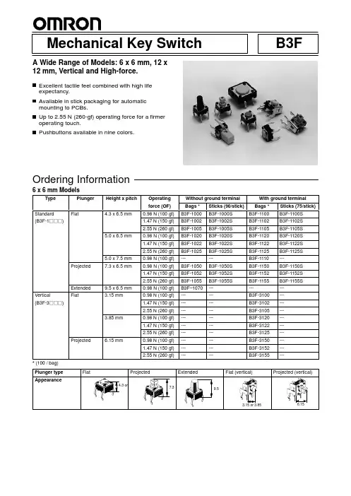
Mechanical Key Switch
A Wide Range of Models: 6 x 6 mm, 12 x 12 mm, Vertical and High-force.
Excellent tactile feel combined with high life expectancy. Available in stick packaging for automatic mounting to PCBs. Up to 2.55 N (260-gf) operating force for a firmer operating touch. Pushbuttons available in nine colors.
nRF24L01P产品说明书V1.0资料
nRF24L01+单片机2.4 GHz收发器产品说明书v1.0主要功能:全球通用的2.4 GHz ISM波段操作250kbps, 1Mbps and 2Mbps空中数据传输速率超低功率运行发射功率为0dBm(1.0mW)时,发射电流为11.3mA2Mbps空中数据传输速率,接收电流为13.5mA掉电电流为900nA待机-I电流26μA片内电压调整器1.9至3.6V电源供电范围增强型ShockBurst TM自动数据包处理自动包数据包事务处理6数据通道的MultiCeiver TM与nRF24L01嵌入式兼容空中数据速率250kbps 和1Mbps,与nRF2401A,nRF2402, nRF24E1和nRF24E2兼容低BOM成本±60ppm 16MHz晶振容许5V输入紧凑的20引脚4x4mm QFN封装应用无线 PC外围设备鼠标,键盘和遥控器三和一桌面捆绑先进的媒体中心遥控器网络电话耳机游戏控制器蓝牙模块运动手表和传感器消费电子产品射频遥控器家庭和商业自动化超低功率无线传感器网络RFID 射频识别资产跟踪系统玩具免责条款北欧半导体ASA有权做出随时更改,提高产品可靠性、功能或设计,不另行通知。
北欧半导体ASA不承担由于应用程序或使用任何所述产品或电路引起的责任。
所有应用程序的信息咨询,不构成说明书的组成部分。
极限值超过一个或多个限制的应力可能会造成设备永久性损坏。
这些应力等级只有在这样或那样的操作环境中提出,在规范中没有给出。
长时间暴露在限制值附近可能会影响设备的可靠性。
生命支持应用这些产品并非为因故障会引起人身伤害的维生装备,设备或系统设计的。
北欧半导体ASA客户使用或出售这些产品,他们将自担风险并同意完全赔偿北欧半导体ASA因使用不当或销售行为造成任何损害。
详细联系方式访问www.nordicsemi.no进入北欧半导体销售办事处和全世界的分销商网站总办公室:Otto Nielsens vei 127004 Trondheim电话: +47 72 89 89 00传真: +47 72 89 89 89www.nordicsemi.no写作惯例本产品规范遵循一套排版规则,文档一致,容易阅读。
243NQ100PBF资料
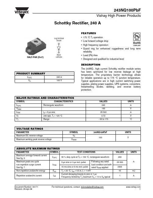
Document Number: 94171For technical questions, contact: ind-modules@Schottky Rectifier, 240 A243NQ100PbFVishay High Power ProductsFEATURES•175 °C T J operation •Low forward voltage drop •High frequency operation•Guard ring for enhanced ruggedness and long term reliability•Lead (Pb)-free•Designed and qualified for industrial levelDESCRIPTIONThe 243NQ.. high current Schottky rectifier module series has been optimized for low reverse leakage at high temperature. The proprietary barrier technology allows for reliable operation up to 175 °C junction temperature.Typical applications are in high current switching power supplies, plating power supplies, UPS systems, converters,freewheeling diodes, welding, and reverse battery protection.PRODUCT SUMMARYI F(AV)240 A V R100 VMAJOR RATINGS AND CHARACTERISTICSSYMBOL CHARACTERISTICSVALUES UNITS I F(AV)Rectangular waveform240A V RRM 100V I FSM t p = 5 µs sine 25 500A V F 240 Apk, T J = 125 °C 0.72V T JRange- 55 to 175°CVOLTAGE RATINGSPARAMETERSYMBOL243NQ100PbFUNITS Maximum DC reverse voltageV R 100VMaximum working peak reverse voltageV RWMABSOLUTE MAXIMUM RATINGSPARAMETER SYMBOL TEST CONDITIONSVALUES UNITSMaximum average forward current See fig. 5I F(AV)50 % duty cycle at T C = 132 °C, rectangular waveform 240A Maximum peak one cycle non-repetitive surge current See fig. 7I FSM 5 µs sine or 3 µs rect. pulseFollowing any rated load condition and with rated V RRM applied25 50010 ms sine or 6 ms rect. pulse 3300Non-repetitive avalanche energy E AS T J = 25 °C, I AS = 5.5 A, L = 1 mH15mJ Repetitive avalanche currentI ARCurrent decaying linearly to zero in 1 µsFrequency limited by T J maximum V A = 1.5 x V R typical1A 元器件交易网 For technical questions, contact: ind-modules@Document Number: 94171243NQ100PbFVishay High Power Products Schottky Rectifier, 240 ANote(1)Pulse width = 500 µsELECTRICAL SPECIFICATIONSPARAMETER SYMBOLTEST CONDITIONSV ALUES UNITSMaximum forward voltage drop See fig. 1V FM (1)240 AT J = 25 °C 0.95V 480 A 1.26240 A T J = 125 °C 0.72480 A0.85Maximum reverse leakage current See fig. 2I RM T J = 25 °C V R = Rated V R6mA T J = 125 °C80Maximum junction capacitance C T V R = 5 V DC (test signal range 100 kHz to 1 MHz) 25 °C 5500pF Typical series inductance L S From top of terminal hole to mounting plane 5.0nH Maximum voltage rate of change dV/dtRated V R10 000V/µs THERMAL - MECHANICAL SPECIFICATIONSPARAMETERSYMBOL TEST CONDITIONSVALUES UNITS Maximum junction and storage temperature range T J , T Stg - 55 to 175°CMaximum thermal resistance,junction to caseR thJC DC operation See fig. 40.19°C/WTypical thermal resistance, case to heatsink R thCSMounting surface, smooth and greased0.05Approximate weight 30g 1.06oz.Mounting torque minimum Non-lubricated threads3 (26.5)N ⋅ m (lbf ⋅ in)maximum 4 (35.4)Terminal torque minimum 3.4 (30)maximum5 (44.2)Case styleHALF-PAK module元器件交易网Document Number: 94171For technical questions, contact: ind-modules@243NQ100PbFSchottky Rectifier, 240 AVishay High Power ProductsFig. 1 - Maximum Forward Voltage Drop CharacteristicsFig. 2 - Typical Values of Reverse Current vs.Reverse VoltageFig. 3 - Typical Junction Capacitance vs. Reverse VoltageFig. 4 - Maximum Thermal Impedance Z thJC Characteristics元器件交易网 For technical questions, contact: ind-modules@Document Number: 94171243NQ100PbFVishay High Power Products Schottky Rectifier, 240 AFig. 5 - Maximum Allowable Case Temperature vs.Average Forward CurrentFig. 7 - Maximum Non-Repetitive Surge CurrentFig. 8 - Unclamped Inductive Test CircuitNote(1)Formula used: T C = T J - (Pd + Pd REV ) x R thJC ;Pd = Forward power loss = I F(AV) x V FM at (I F(AV)/D) (see fig. 6);Pd REV = Inverse power loss = V R1 x I R (1 - D); I R at V R1 = Rated V R元器件交易网元器件交易网Schottky Rectifier, 240 A Vishay High Power ProductsORDERING INFORMATION TABLELINKS TO RELATED DOCUMENTSDimensions /doc?95020Document Number: 94171For technical questions, contact: ind-modules@ Disclaimer Legal Disclaimer NoticeVishayAll product specifications and data are subject to change without notice.Vishay Intertechnology, Inc., its affiliates, agents, and employees, and all persons acting on its or their behalf (collectively, “Vishay”), disclaim any and all liability for any errors, inaccuracies or incompleteness contained herein or in any other disclosure relating to any product.Vishay disclaims any and all liability arising out of the use or application of any product described herein or of any information provided herein to the maximum extent permitted by law. The product specifications do not expand or otherwise modify Vishay’s terms and conditions of purchase, including but not limited to the warranty expressed therein, which apply to these products.No license, express or implied, by estoppel or otherwise, to any intellectual property rights is granted by this document or by any conduct of Vishay.The products shown herein are not designed for use in medical, life-saving, or life-sustaining applications unless otherwise expressly indicated. Customers using or selling Vishay products not expressly indicated for use in such applications do so entirely at their own risk and agree to fully indemnify Vishay for any damages arising or resulting from such use or sale. Please contact authorized Vishay personnel to obtain written terms and conditions regarding products designed for such applications.Product names and markings noted herein may be trademarks of their respective owners.元器件交易网Document Number: 。
FR24中文资料
25 50 75 100 125 150 175 ° Ambient Temperature (°C)
100 10 Number of Cycles @ 60 Hz
Typical Instantaneous Forward Characteristics 100 Forward Current (A)
FR20 . . . 210 Series Maximum Ratings Peak Repetitive Reverse Voltage...VRRM RMS Reverse Voltage...VR(rms) DC Blocking Voltage...VDC Average Forward Rectified Current...IF(av) TA = 55°C Non-Repetitive Peak Forward Surge Current...IFSM @ Rated Current & Temp Operating & Storage Temperature Range...TJ, TSTRG Electrical Characteristics Maximum Forward Voltage @ 2.0A...VF Maximum DC Reverse Current...IR @ Rated DC Blocking Voltage @ @ 25°C 100°C ............................................. 1.3 ............................................... FR20 50 35 50 FR21 100 70 100 FR22 200 140 200 FR24 400 280 400 FR26 600 420 600 FR28 800 560 800 FR210 1000 700 1000
FLX自调节加热电缆产品规格表说明书
FLX TMSelf-Regulating Heating CableProduct SpecificationsApplication: Freeze ProtectionFLX self-regulating heating cables are designed to provide freeze protection and temperature mainte-nance to metallic and nonmetallic pipes, tanks and equipment. FLX heating cables are rated for heat outputs of 10, 16, 26 and 33 watts/meter at 10°C when powered at 230 Vac. FLX is a proven, simple, practical solution for both metal and plastic pipes.Rugged and Reliable . . .FLX self-regulating cables are protected by a tinned copper braid and a polyolefin outer jacket to provide grounding and additional mechanical protection for the cable. An optional fluoropolymer outer jacket is available if additional environmental protection is required.Heat tracing users expect quality products and ser-vices from a reputable manufacturer. Thermon ex-ceeds these expectations by operating under the ISO 9001 standard for quality.THERMON . . . The Heat Tracing Specialists ®Easy to Design . . .Whether the application is a small project or a com-plex network of piping and equipment, designing an electric heat traced freeze protection system is easy with Thermon self-regulating cables. A simple cable selection chart based on pipe size confirms product application; see selection guide for details.With parallel circuitry, self-regulating cables do not require piping dimensions and can be cut to length in the field. Heat tracing circuits for field-routed piping can be quickly and easily designed on site.Easy to Install . . .FLX is installed directly on metallic or nonmetallic piping under conventional thermal insulation with ordinary hand tools. Kits for power connection, end termination and splicing, plus other accessories, are designed for quick and easy installation.Simply pull FLX from the supply reel, install directly on the pipe and complete circuit fabrication. Teesplices may be installed anywhere along the circuit to match the layout of the piping.Corporate Headquarters100 Thermon Dr. •PO Box 609San Marcos, TX 78667-0609 •USA Phone: +1 512-396-5801European HeadquartersBoezemweg 25 •PO Box 2052640 AE Pijnacker •The Netherlands Phone: +31 (0) 15-36 15 370For the Thermon office nearest youvisit us at . . FLX TMSelf-Regulating Heating CableProduct SpecificationsCircuit Breaker Sizing and Type . . .Power Output Curves . . .Pipe Temperature °CW a t t s p e r M e t e r2530020405003020351015105FLX at 230 Vac60Form CPD1007U-0307 © Thermon Manufacturing Co. Specifications are subject to change without notice.40Characteristics . . . Nominal Outside Dimension . . .No. 2043400Certifications/Approvals . . .Bus wire ................................................................................................................................................1,3 mm nickel-plated copper Metallic braid ................................................................................................................................................................tinned copper Outer jacket ...............................................................................................................................-OJ, polyolefin; -FOJ, fluoropolymer Minimum bend radius @ -15°C ..........................................................................................................................................................................10 mm @ -60°C ..........................................................................................................................................................................32 mm Supply voltage .......................................................................................................................................................................230 Vac Circuit protection .................................................................................................................30 mA ground-fault protection required Maximum continuous exposure temperature ...............................................................................power-on: 65°C; power-off: 85°C。
LDS100-24-U00;LDS100-24-H00;LDS100-24-H03;LDS100-31-H03;LDS100-48-H03;中文规格书,Datasheet资料
Output Current
0 – 10V Signal
Emerson Network Power. The global leader in enabling business-critical continuity. AC Power Connectivity DC Power Embedded Computing Embedded Power Monitoring Outside Plant Power Switching & Controls Precision Cooling Racks & Integrated Cabinets Services Surge Protection
Embedded Power for Business-Critical Continuity
Environmental Specifications
Criteria Power Factor Harmonics THD - Input Current Surge Immunity EMC Compliance Temperature (case) Ingress Protection -40 °C to 90 °C IP64 through IP66 > 0.9 Class C < 20% Level 3 6 kV ring wave Specification Energy Star IEC 61000-3-2 ANSI C82.11 IEC 61000-4-5 ANSI C62.41 IEC 61000-4-2, -3, -4, -5, -6, -8, -11 Operating Refer to model table for details Reference
Asia (HK)
FX-100 商品说明资料 中文(简体字) 20061226解读
光量
※FX-100的4元素发光素子能对应长期光量变动, 所以不需搭载APC电路。
強制补正
时间 素子使用寿命
8
社外秘
建议使用市场出售的连接器、不使用中继连接器
光纤放大器 连接器型
传感器制造商专用 的帶连接器电缆
加工成用户规格的连接器
转入PLC、PC等控制系
光纤放大器 电缆外伸型
如用户可將连接器加工成日本压接端子制造的连接器(见下图)的话...
社外秘
数字显示光纤传感器 FX-100 series 商品说明资料
针对PEWA的说明资料。 严禁对外(包括代理店)流出。
2006年11月 SUNX株式会社 海外营业部
1
社外秘
1.目标市场
2
Line Up
商品体系 FX-300 FX-301 FX-305 数字显示 SUNX标准型 高功能型
社外秘
FX-400
PRO模式
高标准设定
可进行外部设定,以及自动跟 踪基准值等高标准设定
与压力传感器DP-100的操作結构相同。 与压力传感器DP-100配套使用、可统一操作性,易于理解。 与DP-100相同,具有2画面显示, 通过『直接调节』易於变更基准值。
12
社外秘
RUN模式
[变更基准值] 提高基准值時 :按ON按钮。
MODE
设定定时
[可设定以下时间] 1ms、5ms、10ms、20ms、40ms、 50ms、100ms、500ms、1s、
M3贯穿孔 ※不使用金属支架也可 直接安装
4芯电缆 按照 茶色:+ 蓝色:- 黑色:out 白色:in 搭载外部输入线。 ・可进行外部设定。
★采用4元素发光素子 不易老化!!