MWT7EJB1
金风1500kw机组电控部分原理介绍

前言目录第一章金风1500KW系列风力发电机组冷却系统简介 (5)一散热系统概述 (5)1.1 散热形式简介 (5)二金风1.5MW系列风机冷却系统类别 (5)2.1 风冷系统 (5)2.1.1 MW风机Freqcon变流器热源 (5)2.1.2 MW风机Freqcon变流器主要器件散热设计目标 (7)2.1.3 MW风机Freqcon变流器风冷散热系统 (8)2.1.4 风冷系统主要器件清单 (9)2.2 水冷系统 (10)2.2.1 MW风机水冷变流器介绍 (10)2.2.2 MW风机水冷散热系统 (11)2.2.3 水冷系统主要元器件清单 (12)第二章金风1500KW系列风力发电机组变桨系统介绍 (13)---- Vensys变桨系统 (13)一变桨电气系统功能 (13)二变桨系统在轮毂内的拓扑结构 (13)三变桨电气系统组成 (15)3.1 变桨柜内部组成 (15)3.2 控制柜外部驱动及检测部分 (22)四变桨系统软件变量定义 (24)4.1 主PLC与BC3150之间交互的信息 (24)4.2 铂电阻测量模块KL3204 (25)4.3 模拟量输入模块KL3404 (26)4.4 模拟量输出模块KL4001 (26)-----LUST变桨系统 (27)一系统简介 (27)1.1 原理结构 (27)1.2 工作模式 (27)1.3 工作模式切换 (27)1.4 柜内元器件布局 (28)二系统结构组成 (28)2.1 电源 (28)2.2 总线与安全链 (28)2.3 主要部件介绍 (29)----SSB变桨系统 (32)一系统简介 (32)1.1 原理结构 (32)二 SSB变桨系统工作模式 (32)2.1 “自动”操作模式 (32)2.2 “紧急 (EFC)”操作模式 (33)2.3 “手动”操作模式 (33)三变桨系统硬件组成 (34)3.1 变桨系统组成 (34)3.2 SSB变桨系统的工作模式 (37)3.3 SSB变桨系统的安全链 (37)第三章金风1500KW系列风力发电机组变流系统介绍 (39)---- SWITCH变流系统 (39)一概述 (39)1.1 能量转换功能 (39)1.2 低电压穿越功能 (39)二变流器的主要技术参数 (39)2.1 网侧功率模块(1U1) (39)2.2 电机侧功率模块(2U1、3U1) (40)2.3 直流制动功率模块(4U1) (40)2.4 网侧断路器(1Q1) (40)2.5 网侧断路器(2Q1、2Q2) (40)三变流器主拓扑结构及原理介绍 (40)3.1 网侧控制原理 (41)3.2 电机侧控制原理 (41)四变流器起停控制 (42)4.1 变流器启动控制 (42)4.2 变流器停止控制 (42)4.3 变流器故障控制 (43)五变流器通讯控制 (43)5.1 变流器内部通讯 (43)5.2 硬件信号 (43)5.3 变流和主控之间通讯数据 (43)六变流器功率因数及功率裕度计算 (44)6.1 输出功率理论计算 (45)6.2 输出功率实际计算 (46)---- FREQCON变流系统 (48)一主回路功能与设计 (48)1.1 主回路拓扑 (48)1.2 主回路拓扑功能 (49)1.3 主回路参数设计 (49)二主回路控制器设计 (53)2.1 Boost电流控制 (53)2.2 网侧逆变器控制 (54)三逻辑功能与故障保护 (58)3.1 变流器启动 (58)3.2 变流器停机 (59)3.3 系统采样 (59)3.4 变流器故障保护 (59)3.5 功率模块硬件保护 (59)第四章金风1500KW系列风力发电机组主控系统介绍 (60)一概述 (60)二主控制柜 (63)三机舱控制柜 (64)四主控系统使用PLC模块 (65)4.1 主站接口模块 (65)4.2 CPU模块 (65)4.3 CPU电源模块 (66)4.4 总线供电模块 (67)4.5 总线耦合器模块 (67)4.6 通道数字量输入模块 (67)4.7 通道数字量输出模块 (68)4.8 通道模拟量输入模块 (68)4.9 通道模拟量输入模块 (69)4.10 三相电力测量模块 (69)五传感器 (70)5.1 温度测量传感器(PT100) (70)5.2 接近开关 (70)5.3 振动加速度传感器 (70)5.4 风向标和风速仪 (70)5.5 机舱位置传感器 (71)第五章金风1500KW系列风力发电机组防雷接地系统简介 (71)一雷电的产生及危害 (71)二防雷接地系统设计说明 (73)2.1 防雷系统设计的基本方法 (73)2.2 雷电接受和传导途径 (74)2.3 叶片部分防雷接地 (74)2.4 机舱部分防雷接地 (74)2.5 机组基础防雷接地 (74)2.6 过压保护和等电位连接 (75)2.7 电控系统防雷 (75)第六章金风1500KW系列风力发电机组现场总线简介 (76)一现场总线定义 (76)二 PROFIBUS–DP介绍 (78)2.1 PROFIBUS–DP的特点 (78)2.2 PROFIBUS-DP的构成 (78)三金风1500KW机组总线组成 (79)3.1 1500KW机组的profibus拓扑结构如下 (79)3.2 金风1500KW机组profibus特性 (79)3.3 金风1500KW机组profibus通讯测量 (79)第一章金风1500KW系列风力发电机组冷却系统简介一散热系统概述众所周知,集成电路技术的快速发展,导致各种电子器件和产品的体积越来越小,集成器件周围的热流密度越来越大,如金风科技MW机风机中变流器IGBT上热流密度最高可达︒水平30w/cm2。
通信建设工程预算定额第三册无线通信设备安装工程

通信建设工程预算定额第三册无线通信设备安装工程中华人民共和国工业和信息化部二00八年五月工业和信息化部文献工信部规[2023]75号有关公布《通信建设工程概算预算编制措施》及有关定额旳告知各省、自治区、直辖市通信管理局,中国电信集团企业、中国网络通信集团企业、中国移动通信集团企业、中国联合通信有限企业、中国卫星通信集团企业、中国铁通集团有限企业:为适应通信建设发展需要,合理和有效控制工程建设投资,规范通信建设概算、预算旳编制与管理,根据国家法律、法规及有关规定,我部修订了《通信建设工程概算、预算编制措施及费用定额》(邮部【1995】626号)以及通信建设工程预算定额等原则。
新修订旳通信建设工程概算、预算定额配套文献包括:《通信建设工程概算、预算编制措施》,《通信建设工程费用定额》,《通信建设工程施工机械、仪器仪表台班定额》,《通信建设工程预算定额》(共五册:第一册通信电源设备安装工程、第二册有线通信设备安装工程、第三册无线通信设备安装工程、第四册通信线路工程、第五册通信管道工程)。
现予公布,自2008年7月1日起实行。
自实行之日起原邮电部《有关公布<通信建设工程概算、预算编制措施及费用定额>等原则旳告知》(邮部【1995】626号)以及《有关公布<通信建设工程施工机械台班费用定额>等2项定额原则旳告知》(邮部【1996】528号)同步废止。
附件:1.通信建设工程概算、预算编制措施2.通信建设工程费用定额3.通信建设工程施工机械、仪器仪表台班定额4.通信建设工程预算定额中华人民共和国工业和信息化部(章)二00八年五月二十四日(附件另发)主题词:邮电通信建设预算告知抄送:国家发展和改革委员会,财政部,住房和城镇建设部。
工业和信息化部办公厅2008年5月27日印发总说明一、通信建设工程预算定额(如下简称本定额)系通信行业原则。
二、本定额按通信专业工程分册,包括:第一册通信电源设备安装工程(册名代号TSD)第二册有线通信设备安装工程(册名代号TSY)第三册无线通信设备安装工程(册名代号TSW)第四册通信线路工程(册名代号TXL)第五册通信管道工程(册名代号TGD)三、本定额是编制通信建设项目投资估算、概算、预算和工程量清单旳基础。
恒达微波波导魔T功率分配器 合成器说明书

1.6功率分配器/合成器【产品简介】恒达微波提供一系列高性能的波导魔T 、功分器、合成器产品。
在魔T 的H 臂或E 臂接上负载,则可制成魔T 功率分配器或合成器。
波导魔T 具有如下特点:平衡臂两端对称;从E 臂输入的信号会在平衡臂两端等幅反相输出,H 臂隔离;从H 臂输入的信号会在平衡臂两端等幅同相输出,E 臂隔离;从平衡臂任一端输入的信号在E 臂和H 口等分输出,而对应平衡臂另一端隔离。
因此魔T 具有的对口隔离、邻口3dB 耦合及完全匹配的特点,使之在微波领域获得了广泛应用,尤其用在单脉冲雷达和差比较器、雷达收发开关、功率分配/合成、混频器及移相器等场合。
【型号描述】波导魔T ,波导管型号BJ100,材料为铝(材料为铜时缺省)。
产品类型:波导魔TH D - 100 W M T A波导管型号:B J 100恒达微波材料:铝【产品类型】类型代码含义类型代码含义WET 波导ET 接头WHT 波导HT 接头WMTPC 波导同相功率合成器WMTPD 波导同相功率分配器WMT 波导魔TWSWC 波导90°功率分配器/合成器(窄边耦合);I\U\XY\YU 型WTWC波导90°功率分配器/合成器(宽边耦合);I\U\XY\YU 型1.6.1波导ET 接头、波导HT 接头这两种器件在微波系统中常用作功率分配/合成元件。
波导ET 接头可以将E 口输入的信号在平衡臂两端等幅反相输出,反之,在平衡臂两端等幅反相输入信号则在E 口合成输出;波导HT 接头可以将H 口输入的信号在平衡臂等幅同相输出,反之,在平衡臂两端等幅同相输入信号则在H 口合成输出,但是ET 、HT 接头是不匹配的器件,只对其E 口或是H 口进行单端口匹配。
1.6.1.1波导ET 接头【标准产品数据表】产品型号频率范围(GHz)工作带宽对称性(dB)E口驻波比插损(dB)法兰材料涂覆HD-3WET0.32-0.49≤15%±0.25≤1.15≤0.2FDP铝氧化HD-4WET0.35-0.53≤15%±0.25≤1.15≤0.2FDP铝氧化HD-5WET0.41-0.62≤15%±0.25≤1.15≤0.2FDP铝氧化HD-6WET0.49-0.75≤15%±0.25≤1.15≤0.2FDP铝氧化HD-8WET0.64-0.98≤15%±0.25≤1.15≤0.2FDP铝氧化HD-9WET0.75-1.15≤15%±0.25≤1.15≤0.2FDP铝氧化HD-12WET0.96-1.46≤15%±0.25≤1.15≤0.2FDP铝氧化HD-14WET 1.13-1.73≤15%±0.25≤1.15≤0.2FDP铝氧化HD-18WET 1.45-2.20≤15%±0.25≤1.15≤0.2FDP铝氧化HD-22WET 1.72-2.61≤15%±0.25≤1.15≤0.2FDP铝氧化HD-26WET 2.17-3.30≤15%±0.25≤1.15≤0.2FDP铝氧化HD-32WET 2.60-3.95≤15%±0.25≤1.15≤0.2FDP铝氧化HD-40WET 3.22-4.90≤15%±0.25≤1.15≤0.2FDP铝氧化HD-48WET 3.94-5.99≤15%±0.35≤1.20≤0.2FDP铝氧化HD-58WET 4.64-7.05≤15%±0.35≤1.20≤0.2FDP铝氧化HD-70WET 5.38-8.17≤15%±0.35≤1.20≤0.3FDP铜镀银HD-84WET 6.57-9.99≤15%±0.35≤1.20≤0.3FBP铜镀银HD-100WET8.20-12.40≤15%±0.35≤1.20≤0.3FBP铜镀银HD-120WET9.84-15.0≤15%±0.35≤1.20≤0.3FBP铜镀银HD-140WET11.9-18.0≤15%±0.40≤1.25≤0.3FBP铜镀银HD-180WET14.5-22.0≤15%±0.40≤1.25≤0.4FBP铜镀银HD-220WET17.6-26.7≤15%±0.40≤1.25≤0.4FBP铜镀银HD-260WET21.7-33.0≤15%±0.40≤1.25≤0.4FBP铜镀银HD-320WET26.5-40.0≤15%±0.40≤1.25≤0.4FBP铜镀银HD-400WET32.9-50.1≤10%±0.50≤1.35≤0.5FUGP铜镀金HD-500WET39.2-59.6≤10%±0.50≤1.35≤0.5FUGP铜镀金HD-620WET49.8-75.8≤10%±0.50≤1.35≤0.5FUGP铜镀金HD-740WET60.5-91.9≤10%±0.50≤1.35≤0.5FUGP铜镀金HD-900WET73.8-112≤10%±0.50≤1.35≤0.5FUGP铜镀金1.6.1.2波导HT 接头【标准产品数据表】产品型号频率范围(GHz)工作带宽对称性(dB)H 口驻波比插损(dB)法兰材料涂覆HD-3WHT 0.32-0.49≤15%±0.25≤1.15≤0.2FDP 铝氧化HD-4WHT 0.35-0.53≤15%±0.25≤1.15≤0.2FDP 铝氧化HD-5WHT 0.41-0.62≤15%±0.25≤1.15≤0.2FDP 铝氧化HD-6WHT 0.49-0.75≤15%±0.25≤1.15≤0.2FDP 铝氧化HD-8WHT 0.64-0.98≤15%±0.25≤1.15≤0.2FDP 铝氧化HD-9WHT 0.75-1.15≤15%±0.25≤1.15≤0.2FDP 铝氧化HD-12WHT 0.96-1.46≤15%±0.25≤1.15≤0.2FDP 铝氧化HD-14WHT 1.13-1.73≤15%±0.25≤1.15≤0.2FDP 铝氧化HD-18WHT 1.45-2.20≤15%±0.25≤1.15≤0.2FDP 铝氧化HD-22WHT 1.72-2.61≤15%±0.25≤1.15≤0.2FDP 铝氧化HD-26WHT 2.17-3.30≤15%±0.25≤1.15≤0.2FDP 铝氧化HD-32WHT 2.60-3.95≤15%±0.25≤1.15≤0.2FDP 铝氧化HD-40WHT 3.22-4.90≤15%±0.25≤1.15≤0.2FDP 铝氧化HD-48WHT 3.94-5.99≤15%±0.35≤1.20≤0.2FDP 铝氧化HD-58WHT 4.64-7.05≤15%±0.35≤1.20≤0.2FDP 铝氧化HD-70WHT 5.38-8.17≤15%±0.35≤1.20≤0.3FDP 铜镀银HD-84WHT 6.57-9.99≤15%±0.35≤1.20≤0.3FBP 铜镀银HD-100WHT 8.20-12.40≤15%±0.35≤1.20≤0.3FBP 铜镀银HD-120WHT 9.84-15.0≤15%±0.35≤1.20≤0.3FBP 铜镀银HD-140WHT 11.9-18.0≤15%±0.40≤1.20≤0.3FBP 铜镀银HD-180WHT 14.5-22.0≤15%±0.40≤1.25≤0.4FBP 铜镀银HD-220WHT 17.6-26.7≤15%±0.40≤1.25≤0.4FBP 铜镀银HD-260WHT 21.7-33.0≤15%±0.40≤1.25≤0.4FBP 铜镀银HD-320WHT 26.5-40.0≤15%±0.40≤1.25≤0.4FBP 铜镀银HD-400WHT32.9-50.1≤10%±0.50≤1.35≤0.5FUGP铜镀金产品型号频率范围(GHz)工作带宽对称性(dB)H 口驻波比插损(dB)法兰材料涂覆HD-500WHT 39.2-59.6≤10%±0.50≤1.35≤0.5FUGP 铜镀金HD-620WHT 49.8-75.8≤10%±0.50≤1.35≤0.5FUGP 铜镀金HD-740WHT 60.5-91.9≤10%±0.50≤1.35≤0.5FUGP 铜镀金HD-900WHT73.8-112≤10%±0.50≤1.35≤0.5FUGP铜镀金1.6.2波导魔T【标准产品数据表】产品型号频率范围(GHz)工作带宽驻波比隔离度(E-H )(dB)对称性(dB)法兰材料涂覆H 口E 口HD-3WMT 0.32-0.49≤20%≤1.20≤1.50≥35≤0.25FDP 铝氧化HD-4WMT 0.35-0.53≤20%≤1.20≤1.50≥35≤0.25FDP 铝氧化HD-5WMT 0.41-0.62≤20%≤1.20≤1.50≥35≤0.25FDP 铝氧化HD-6WMT 0.49-0.75≤20%≤1.20≤1.50≥35≤0.25FDP 铝氧化HD-8WMT 0.64-0.98≤20%≤1.20≤1.50≥35≤0.25FDP 铝氧化HD-9WMT 0.75-1.15≤20%≤1.20≤1.50≥35≤0.25FDP 铝氧化HD-12WMT 0.96-1.46≤20%≤1.20≤1.50≥35≤0.25FDP 铝氧化HD-14WMT 1.13-1.73≤20%≤1.20≤1.50≥35≤0.25FDP 铝氧化HD-18WMT 1.45-2.20≤20%≤1.20≤1.50≥35≤0.25FDP 铝氧化HD-22WMT 1.72-2.61≤20%≤1.20≤1.50≥35≤0.4FDP 铝氧化HD-26WMT 2.17-3.30≤20%≤1.20≤1.50≥35≤0.4FDP 铝氧化HD-32WMT 2.60-3.95≤20%≤1.20≤1.50≥35≤0.4FDP 铝氧化HD-40WMT 3.22-4.90≤20%≤1.20≤1.50≥35≤0.4FDP 铝氧化HD-48WMT 3.94-5.99≤20%≤1.20≤1.50≥35≤0.4FDP 铝氧化HD-58WMT 4.64-7.05≤20%≤1.20≤1.50≥35≤0.4FDP 铝氧化HD-70WMT 5.38-8.17≤20%≤1.20≤1.50≥35≤0.4FDP 铜镀银HD-84WMT 6.57-9.99≤20%≤1.20≤1.50≥35≤0.4FBP 铜镀银HD-100WMT 8.20-12.4≤20%≤1.20≤1.50≥35≤0.4FBP 铜镀银HD-120WMT 9.84-15.0≤20%≤1.20≤1.50≥35≤0.4FBP铜镀银产品型号频率范围(GHz)工作带宽驻波比隔离度(E-H )(dB)对称性(dB)法兰材料涂覆H 口E 口HD-140WMT 11.9-18.0≤20%≤1.20≤1.50≥35≤0.4FBP 铜镀银HD-180WMT 14.5-22.0≤20%≤1.20≤1.50≥35≤0.4FBP 铜镀银HD-220WMT 17.6-26.7≤20%≤1.20≤1.50≥30≤0.4FBP 铜镀银HD-260WMT 21.7-33.0≤20%≤1.20≤1.50≥30≤0.4FBP 铜镀银HD-320WMT 26.5-40.0≤20%≤1.20≤1.50≥30≤0.4FBP 铜镀银HD-400WMT 32.9-50.1≤20%≤1.20≤1.50≥30≤0.5FUGP 铜镀金HD-500WMT 39.2-59.6≤20%≤1.20≤1.50≥30≤0.5FUGP 铜镀金HD-620WMT 49.8-75.8≤20%≤1.20≤1.50≥30≤0.5FUGP 铜镀金HD-740WMT 60.5-91.9≤20%≤1.20≤1.50≥30≤0.5FUGP 铜镀金HD-900WMT73.8-112≤20%≤1.20≤1.50≥30≤0.5FUGP铜镀金1.6.3波导同相功率分配器/合成器根据波导魔T 所特有的对口隔离、邻口3dB 耦合及完全匹配的特点,可在在波导魔T 的E 臂内置负载,制成波导同相功率分配器/合成器。
欧姆龙NB系列触摸屏安装手册
通过 RS-232C 进行连接.......................................................... 2-5 通过 USB 进行连接.............................................................. 2-5
2
V107-CN5-01TOC.fm Page 3 Thursday, October 13, 2011 1:18 PM
目录
第 5 章 维护保养和故障排除
5-1 维修保养 ........................................................ 5-1 5-2 故障排除和维修保养 .............................................. 5-2
附录 -5 型号一览 .................................................. 附 -11 附录 -6 选购件一览 ................................................ 附 -15
NB 系列 可编程终端 安装手册
1
V107-CN5-01.book Page 2 Wednesday, October 12, 2011 5:33 PM
目录
注意事项 ........................................................ 1 本手册内容 ...................................................... 4 相关手册 ........................................................ 5 术语 ............................................................ 6 介绍 ............................................................ 7 安全注意事项 .................................................... 8 安全要点 ....................................................... 10 使用注意事项 ................................................... 12 关于符合 EC 指令 ................................................ 13 阅读并理解本手册 ............................................... 14 第 1 章 各部分的名称和功能
系列通用变频器使用说明书

监视功能分为运行监视功能和故障及故障查询监视功能两 种。 ① 运行监视功能
运行时可监视输出频率/PID 反馈、输入参考频率/PID 给 定、输出电流、输出电压、过载率、IGBT 模块温度/程 序运行段数、直流母线电压/程序运行时间。 ② 故障及故障查询监视功能 故障及故障查询可监视当前故障时的输出频率、直流母 线电压、输出电流、运行方向、运行状态、限幅状态、 前 1 次故障、前 2 次故障、前 3 次故障代码。
带回生制动功能特制机型ambg7系列通用变频器使用说明书使用方法22外形尺寸和安装尺寸w1setshiftrunrunerrresto2dresetstopshiftrunsetrunerrsecd1d2ambg7ambitionambg7acdrivesitionacdrivesambg7setseca37kw及以下规格及lcd键盘尺寸ambb15kw及以下规格尺寸图2115kw及以下规格外形尺寸表2115kw及以下外形尺寸和安装尺寸规格d1d2d3ambg7lcd键盘747113213157ambg70r7t3s2ambg71r5t3s2ambg72r2t3s2ambg73r7t315013522020516094516911953ambg75r5t3ambg77r5t320518630028416517310264ambg7011t3ambg7015t325023436034521222214223ambg7系列通用变频器使用说明书使用方法ambg7图22185kw及以上外形尺寸和安装尺寸表22185kw以上外形尺寸和安装尺寸规格h1h2d1d2ambg7018t3ambg7022t3ambg7030t329020052050047526527521510ambg7037t3ambg7045t334824058756754729330324610ambg7055t3ambg7075t341530072069567031032024512ambg7093t3ambg7110t3ambg7132t354046092590286029530523012ambg7160t3ambg7185t3ambg7200t3柜机600lx600wx1800hambg7220t3ambg7245t3ambg7280t3柜机660lx600wx2000h24ambg7系列通用变频器使用说明书使用方法23安装场所要求和管理注意搬运时请托住机体的底部
梭哈7100系列底部挂载驱动器套件标准负载平行扭筒电动机操作与维护手册说明书
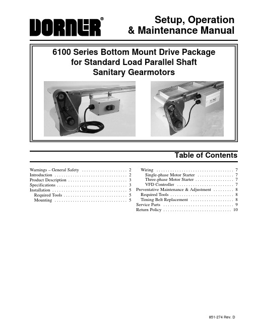
Setup, Operation& Maintenance ManualTable of ContentsWarnings – General Safety2. . . . . . . . . . . . . . . . . . . .Introduction2 . . . . . . . . . . . . . . . . . . . . . . . . . . . . . . . .Product Description3. . . . . . . . . . . . . . . . . . . . . . . . . . Specifications3. . . . . . . . . . . . . . . . . . . . . . . . . . . . . . .Installation5 . . . . . . . . . . . . . . . . . . . . . . . . . . . . . . . . .Required Tools5. . . . . . . . . . . . . . . . . . . . . . . . . . . . Mounting5 . . . . . . . . . . . . . . . . . . . . . . . . . . . . . . . .Wiring7 . . . . . . . . . . . . . . . . . . . . . . . . . . . . . . . . . .Single-phase Motor Starter7. . . . . . . . . . . . . . . .Three-phase Motor Starter7. . . . . . . . . . . . . . . . .VFD Controller7. . . . . . . . . . . . . . . . . . . . . . . . . Preventative Maintenance & Adjustment8. . . . . . . . . Required Tools8. . . . . . . . . . . . . . . . . . . . . . . . . . . . Timing Belt Replacement8. . . . . . . . . . . . . . . . . . . Service Parts9. . . . . . . . . . . . . . . . . . . . . . . . . . . . . . . Return Policy10. . . . . . . . . . . . . . . . . . . . . . . . . . . . . .851-274 Rev. D6100 Series Bottom Mount Drive Package for Standard Load Parallel Shaft Sanitary Gearmotors SOMM851-274 Rev. D 2Dorner Mfg. Corp.IntroductionIMPORTANT: Some illustrations may showguards removed. Do NOT operate equipment with-out guards.Upon receipt of shipment:D Compare shipment with packing slip. Contact factory regarding discrepancies.D Inspect packages for shipping damage. Contact carrier regarding damage.D Accessories may be shipped loose. See accessory in-structions for installation.Dorner 6100 Series conveyors are covered by patent number 5174435 and corresponding patents and patent applications in other countries.Dorner ’s Limited Warranty applies.Dorner reserves the right to make changes at any time without notice or obligation.Warnings – General Safety6100 Series Bottom Mount Drive Package for Standard Load Parallel Shaft Sanitary Gearmotors SOMMDorner Mfg. Corp.3851-274 Rev. DRefer to Figure 1 for typical components.A ConveyorB Mounting BracketC GearmotorD Timing Belt TensionerE CoverF Timing BeltG Drive PulleyH Driven Pulley IMotor ControlTypical ComponentsAB DFFigure 1EGCH ISpecificationsGearmotor Mounting Package Models:Example:Drive/Driven Pulleys (See tables 2 & 3)= Flat Belt (or add cleat type)* See “Ordering and Specifications ” Catalog for details.Table 1: Gearmotor SpecificationsProduct DescriptionSpecificationsTable 2: Standard Load Fixed Speed Parallel Shaft 60 Hz Gearmotors(vp) = voltage and phase11 = 115 V, Single-phase23 = 230 V, Three-phaseTable 3: Standard Load Variable Speed Parallel Shaft VFD Gearmotors* At 60 HzNOTE: For belt speed other than those listed,contact factory for details.6100 Series Bottom Mount Drive Package for Standard Load Parallel Shaft Sanitary Gearmotors SOMM851-274 Rev. D4Dorner Mfg. Corp.6100 Series Bottom Mount Drive Package for Standard Load Parallel Shaft Sanitary Gearmotors SOMMDorner Mfg. Corp.5851-274 Rev. DRequired ToolsD Wrenches (for hexagon head fasteners)7 mm & 10 mm D 2.5 mm hex key wrench D Straight edge D Torque wrenchMountingIllustration ReferencesJ Bottom Mounting Plate Assembly K Drive Pulley L Driven Pulley M KeyN M6 x 30 mm, Hexagon Head Screws (2 x)O Timing Belt P CoverQ Accessory Mounting Clips (2x)R M6 x 20 mm, Hexagon Head Screws (2x)S Typical Motor Starter1.Typical components (Figure 2)NOTE: Three-phase Motor Starter shown, Single-phase Starter or VFD Controller similar.J NO Figure 2LMKPRQS2.Locate drive output shaft (T of Figure 3) and removetwo (2) screws (U).TFigure 3U3.Attach bottom mounting plate assembly (J) withscrews (N). Tighten to 92 in-lb (10.4 Nm).Figure 4JN4.Install key (M of Figure 5).Figure 5LMOK5.Wrap timing belt (O) around driven pulley (L) anddrive pulley (K). Install driven pulley (L) onto conveyor shaft.Installation6100 Series Bottom Mount Drive Package for Standard Load Parallel Shaft Sanitary Gearmotors SOMM851-274 Rev. D 6Dorner Mfg. Corp.ing a straight edge (V of Figure 6), align drivenpulley (L) with drive pulley (K). Tighten driven pulley set screws (W).Figure 6LKVW7.Depending on conveyor belt travel (direction 1 or 2),locate timing belt tensioner (X of Figure 7) asshown. Tension timing belt to obtain 0.125¨ (3 mm)deflection for 1.0 lb (456 grams) of force at timingbelt mid-point (Y). Tighten tensioner screw to 92in-lb (10.4 Nm).12YFigure 7NOTE: Do not over-tighten screws (Z of Figure 8).8.Install cover (P of Figure 8) and tighten four (4)screws (Z) to 35 in-lb (4 Nm).Figure 8PZZ9.Attach accessory mounting clips (Q of Figure 9) toconveyor.Figure 9Q NOTE: Three-phase Motor Starter shown,Single-phase Starter similar. For VFD controller mounting, see accessory instructions.10.Attach motor starter (S of Figure 10) to clips withscrews (R). Tighten to 92 in-lb (10.4 Nm).RR Figure 10SInstallation6100 Series Bottom Mount Drive Package for Standard Load Parallel Shaft Sanitary Gearmotors SOMMDorner Mfg. Corp.7851-274 Rev. DWiringSingle-phase Motor StarterNOTE: Power cord must be plugged into a GFI out-let. No additional wiring is required.Three-phase Motor StarterNOTE: 230 volt three-phase manual motor startersmust be wired in accordance with applicable electrical codes.1.Loosen cover screws (AA of Figure 11). Removecover.ABFigure 11AANOTE: Line cord must be 0.28¨ (7 mm) minimum to0.47¨ (12 mm) maximum in diameter.2.Insert line cord through grip (AB) and tighten nut.3.For correct three-phase motor shaft rotation, con-nect line phase sequence L1, L2 & L3 to terminals as shown (Figure 12).Ground L1L2L3135Figure 12NOTE: left terminal marked4.(see Figure 12).5.Replace starter cover and tighten screws (AA ofFigure 11).VFD ControllersNOTE: Refer to VFD Controller Set-up, Operation &Maintenance Manual.Installation6100 Series Bottom Mount Drive Package for Standard Load Parallel Shaft Sanitary Gearmotors SOMM851-274 Rev. D 8Dorner Mfg. Corp.Required ToolsD Wrenches (for hexagon head fasteners)7 mm & 10 mm D 2.5 mm hex key wrench D Torque wrenchTiming Belt Replacement1.Loosen four (4) screws (Z of Figure 13) and removecover (P).Figure 13ZP Z2.Loosen tensioner (X of Figures 14).Figure 14XO3.Remove timing belt (O).NOTE: If timing belt does not slide over pulleyflange, loosen driven pulley set screws (W of Figure 15) and remove pulley with belt. For re-installation,see steps 5 and 6 on pages 5 and 6.Figure 15W4.Install new timing belt.5.Depending on conveyor belt travel (direction 1 or 2),locate timing belt tensioner (X of Figure 16) as shown. Tension timing belt to obtain 0.125¨ (3 mm)deflection for 1.0 lb (456 grams) of force at timing belt mid-point (Y). Tighten tensioner screw to 92in-lb (10.4 Nm).12YFigure 16NOTE: Do not over-tighten screws (Z of Figure 13).6.Replace cover (P of Figure 13) and tighten four (4)screws (Z) to 35 in-lb (4 Nm).Preventive Maintenance & Adjustment6100 Series Bottom Mount Drive Package for Standard Load Parallel Shaft Sanitary Gearmotors SOMMDorner Mfg. Corp.9851-274 Rev. DNOTE: For replacement parts other than those shown on this page, contact an authorized Dorner Service Center or the factory.Figure 171234567Service PartsReturn PolicyFor replacement parts, contact an authorizedDorner Service Center or the factory.851-274 Rev. D Printed in U.S.A.200。
BC817-16W至BC817-40W NPN 硅通用切换器数据手册说明书

VCE(sat)
Base-Emitter Saturation Voltage
VBE(sat)
Base-Emitter Voltage
VBE
Transition Frequency
fT
100
Collector Capacitance
CC
V IC=10µA, IE=0
V IC=10mA, IB=0
V IE=1µA, IC=0
Internal Structure
3
1 2
1.BASE 2.EMITTER 3.COLLECTOR
NPN Silicon General Purpose
Transistors
SOT-323
A D
3
12
FE
BC
G
H
J
K L
DIMENSIONS
DIM
INCHES MIN MAX
MM MIN MAX
A 0.071 0.087 1.80 2.20
OMRON NB-series 可编程终端操作说明手册说明书
Cat. No. V23I-E-01NB-seriesNB3Q-TW01BNB5Q-TW01BNB7W-TW01BNB10W-TW01BProgrammable Terminals©OMRON, 2013All rights reserved. No part of this publication may be reproduced, stored in a retrieval system, or transmitted, in any form, or by any means, mechanical, electronic, photocopying, recording, or otherwise, without the prior written permission of OMRON.No patent liability is assumed with respect to the use of the information contained herein. Moreover, because OMRON is constantly striving to improve its high-quality products, the information contained in this instruction is subject to change without notice. Every precaution has been taken in the preparation of this instruction.Nevertheless, OMRON assumes no responsibility for errors or omissions. Neither is any liability assumed for damages resulting from the use of the information contained in this publication.NB-seriesNB3Q-TW01BNB5Q-TW01BNB7W-TW01BNB10W-TW01BProgrammable TerminalsWeb Interface Operating Instruction Manual September 2013IntroductionThis instruction describes only the configuration and settings required to use NB Web Interface.Please be sure to read and fully understand related manuals including NB-series manual beforeusing the NB series Programmable Terminal, and read this instruction when using NB Web Interface.Copyright and TrademarkSystem names and product names used in this instruction are the trademarks or registeredtrademarks of their respective companies.Notation and TerminologyIndicate the additional information on operation, descriptions or settings.2NB-series Programmable Terminals Web Operating Instruction Manual (OMSQ-ISV(01) 0362(3/21)ContentsIntroduction (2)Contents (3)1 Overview (4)1-1 What is NB Web Interface? (4)1-2 What NB Web Interface Can Do (5)1-3 Operating Environments (6)1-3-1 Necessary NB Series Configuration (6)1-3-2 Necessary Network Environments (6)1-3-3 Necessary Web Browser (6)2 Using NB Web Interface (7)2-1 Connection Method (7)2-1-1 PT Settings (7)2-1-2 Connecting a Web Browser to a PT (7)3 The Functions of NB Web Interface (9)3-1 A List of the Functions of NB Web Interface (9)3-2 Menu Screen (10)3-3 Monitor Screen (11)3-3-1 Monitor Screen (11)3-3-2 Updating a Screen Display (11)3-3-3 Specifying the Display Image Format of the Monitor Screen (12)3-3-4 Not Using the User Authentication (12)3-4 Operation Screen (13)3-4- 1 Operation Screen (13)3-4-2 Reloading Screen Display (14)4 NB Web Interface Settings (15)4-1 NB Web Interface Settings (15)4-1-1 Configuration Screen (15)4-1-2 NB Web Interface Settings (16)5 Authentication settings (18)5-1 Change user name and password (18)5-2 Default user name and password Restoration (18)6 Troubleshooting (19)6-1 Error Messages (19)Revision History List (20)NB-series Programmable Terminals Web Operating Instruction Manual(OMSQ-ISV(01) 0362(3/21))31 OverviewThis section describes an overview of the functions of NB Web Interface. This also describes the OperatingEnvironments for NB Web Interface.1-1 What is NB Web Interface?NB Web Interface is a function that monitors a screen that an NB-series HMI displays using a web browser on apersonal computer connected via Ethernet to an NB-series HMI (Programmable Terminal called “the PT”).NB Web Interface has the following functions.Monitors a PT screen at the site using a web browser.Operates a PT screen at the site using a web browser.4NB-series Programmable Terminals Web Operating Instruction Manual (OMSQ-ISV(01) 0362(3/21)1-2 What NB Web Interface Can DoThis section contains the usage examples of NB Web Interface.Remote MonitoringNB Web Interface allows users to check error and alarm details displayed on the PT by accessing the enduser’s PT from a web browser. Also when users instruct an operator, users can check work done by theoperator using a web browser.Remote OperationUser can access the PT using a web browser. From a web browser, it is possible to remote control the PT. NB-series Programmable Terminals Web Operating Instruction Manual(OMSQ-ISV(01) 0362(3/21))51-3 Operating EnvironmentsThe following shows the system configuration for connecting a PT on a network to a personal computer usingNB Web Interface.1-3-1 Necessary NB Series ConfigurationNB-series PT ModelsAny of the following NB-series is required to use NB Web Interface.NB Model Lot No.09X13M or aboveNB3Q-TW01BNB5Q-TW01BNB7W-TW01BNB10W-TW01BWhen the NB model above do not have web server function, please use NB-Manager version 1.30 or above toupdate the kernel and file system, for operation detail, please refer to [4-4 System Operate] of NB seriesNB-Designer Operation Manual.NB Designer VersionThe following version of the system program must be installed in your NB-series in order to use the NB WebInterface.NB Designer Version ( including NB Manager)Version 1.30 or later*In the NB-Manager, if there is “Web Interface Operation” option on the left side, it means this NB-Managersupports web server function.*For download the application programs, please access your local Omron website, If local site cannot be found,please access Omron IA global site "/ "at first and select the area where you are.1-3-2 Necessary Network EnvironmentsYour NB-series must be able to be connected to a personal computer via one of the following Ethernet standardin order to use the NB Web Interface.Standard10Base-T or 100Base-TX1-3-3 Necessary Web BrowserThe following web browsers can show a PT screen on a personal computer.Web browserMicrosoft Internet Explorer Ver.8Microsoft Internet Explorer Ver.9Safari (IOS.6x)6NB-series Programmable Terminals Web Operating Instruction Manual (OMSQ-ISV(01) 0362(3/21)2 Using NB Web InterfaceThis section explains how to connect a PT to a web browser on a personal computer using NB Web Interface.2-1 Connection MethodThis section explains a PT how to connect to a web browser on a computer using NB Web Interface. This document uses Windows 8 and Microsoft Internet Explorer Ver.9 as an example. For details on the operating system, the setting of the web browser and operation methods, refer to manuals for each product.2-1-1 PT SettingsTo use NB Web Interface, the following settings must be made in the project of NB.1. Use NB-Designer, open the project which will be download to the PT, add bit button component in theframe, set type to “Alternate” in the bit button property, and set the address to LB9175. 2. Compile and download the project to PT.3. Click the bit button on the PT to switch ON of address LB9175.2-1-2 Connecting a Web Browser to a PTThis section explains how to connect a Web Browser to a PT. 1. Start a web browser. 2. Input the following URL.http://(PT IP Address)/For example, when the PT IP Address is “192.168.0.1”:to 3 The Functions of NB Web Interface .ScreenURLMonitor Screen http://(PT IP Address)/monitor.html Operation Screen http://(PT IP Address)/operation.html Configuration Screen http://(PT IP Address)/config.html Menu Screenhttp://(PT IP Address)/menu.html3. The login screen will be displayed.7NB-series Programmable Terminals Web Operating Instruction Manual (OMSQ-ISV(01) 0362(3/21))ReferenceThe NB Web Interface login uses the Basic Authentication defined by the HTTP.It is possible to set whether to use the user authentication login screen or not when displaying Monitor Screen. Refer to 4 NB Web Interface Settings for the settings. 4. Enter the user name and password.The factory settings for the user name and password are as follows.User name default PassworddefaultReferenceThe user name and password can be changed by NB-Manager, for details please refer to 5 Authentication settings .5. ClickOK Button. The menu screen will be displayed.Item DescriptionMonitorMonitors the screen currently displayed on the PT . OperationMonitors the screen currently displayed on the PT .Operates the PT screen by mouse clicking the web browser.Configuration Make settings related to NB Web Interface.Details on each screen are explained in 3 The Functions of NB Web Interface .ReferenceThe initial screen can be changed by setting. For details on the setting, refer to 4 NB Web Interface Settings .NB-series Programmable Terminals Web Operating Instruction Manual (OMSQ-ISV(01) 0362(3/21)83 The Functions of NB Web InterfaceThis section explains the functions of NB Web Interface.3-1 A List of the Functions of NB Web InterfaceNB Web Interface has the following functions (screens).Detail ContentMenu screen The menu screen of NB Web Interface.Monitor screen Monitors the screen currently displayed on the PT.Operation screen Monitors the screen currently displayed on the PT.Also operates the PT screen by mouse clicking the web browser.Configuration screen Make settings related to NB Web Interface.ReferenceFor Configuration screen, refer to 4 NB Web Interface Settings.The Menu screen displays the following screen.ItemDescriptionMenu screenDisplays a list of the NB Web Interface screens. Clicking will jump to each screen.Microsoft product screen shot(s) reprinted with permission from Microsoft Corporation.3-3-1 Monitor ScreenThe Monitor screen is used to display a PT screen.It displays the screen as follow. (e.g.)No.Item Description1Monitor Screen Displays a PT screen.2Latest Captured Displays the date and time when a PT screen was read. ReferenceA PT screen cannot be operated with the Monitor screen.To operate a screen, please enter into the Operation screen.To hide the Latest Captured time, should be set in configuration page. For details on the setting, refer to 4 NB Web Interface Settings.3-3-2 Updating a Screen DisplayThe Monitor Screen periodically reads a screen displayed on the PT and updates the screen in a certain interval set in the Configuration screen. (Default: 15 seconds) For details on the setting, refer to 4 NB Web Interface Settings.3-3-3 Specifying the Display Image Format of the Monitor ScreenNB Web Interface displays a Windows BMP, JPEG or PNG format image of a PT screen on a web browser. To select one of the formats, make a setting in the Configuration screen.ReferenceThe display picture format settings in the Configuration screen will also be used for the Operation screen. 3-3-4 Not Using the User AuthenticationIt is possible to set whether or not to use the user authentication (Login screen display) when directly specifying a URL to open the Monitor screen. For details on the setting, refer to 4 NB Web Interface settings.3-4 Operation Screen3-4-1 Operation ScreenThe Operation screen is used to display the PT screen and operate the screen. The Operation screen displays the following screen. (e.g.)Item DescriptionOperation screenDisplays the PT screen.Allows the user to operate the PT screen by clicking the web browser.ReferenceIt is possible to prohibit operating the PT screen from the PT while operating the PT screen from the Operation screen. For details, refer to 4 NB Web Interface Settings .3-4-2 Reloading Screen DisplayThe Operation screen periodically reads a screen displayed on the PT and updates the display. The reload interval can be set in the Configuration screen (Default: 3 seconds).It is also possible to set the time from when the user mouse clicks until the Operation screen reads a PT screen and updates the display. (Default: 1 second).For details on the setting, refer to 4 NB Web Interface Settings.ReferenceThe Reload Interval in the Monitor screen and Reload Interval in the Operation screen are independent from each other. Thus, they must be set separately.4 NB Web Interface SettingsThis section explains the NB Web Interface settings.4-1 NB Web Interface Settings4-1-1 Configuration ScreenThe Configuration Screen is used to make settings for NB Web Interface. 1. Display the Configuration screen.No. Item Description1 Setting Items Settings for NB Web Interface.For details on the settings, refer to 4-1-2 NB Web Interface Settings . 2 apply Reflects the setting changes in NB Web Interface. 3 save Reflects the setting changes in NB Web Interface. Also saves those changes in the PT. 4 default Returns all settings to the default settings.5resetCancels the setting changes currently being input, and returns to the settings before change.(return to the last valid settings)2. Set each item, then click apply or save button.3. A window stating of configuration done is displayed.4. When three seconds elapsed after “Configuration Done” screen is displayed, the window automaticallydisplays a screen set for Initial Page.4-1-2 NB Web Interface SettingsSetting items in the Configuration screen are explained here.Monitor SettingItem Description Correspondingscreen Reload Interval Set the time from when the Monitor screen reads a PT screenuntil when it next reads the NB screen. Between 2 and 99seconds can be set. (Default: 15 seconds)Monitor screenDisplay Pic Format Set which images format used when a PT screen istransferred. There are three formats can be select: BMP, JPEGand PNG. (Default: BMP)-Checked: Use-Unchecked: Not useWhen PNG images are used, user can set the compressionlevel for PNG formats in the option “Compression Level”.Monitor screen, Operation screenPNG Compression Level Set the compression level for creating PNG data. Between0(Compression non destructive) and 8(Highest compressionrate) can be set. (Default: 3)Only enable when selected PNG format in “Display PicFormat”.Monitorscreen,OperationscreenDisplay Date and Time Set whether to display the date and time when the PT scre enis captured on the bottom of Monitor screen. (Defau lt:Selected)-Checked: Displayed-Unchecked: Not displayedMonitor screenUse Authentication Set whether to use the user authentication or not whenspecifying a URL for Monitor screen. (Default: Unchecked)-Checked: User authentication used-Unchecked: User authentication not usedMonitor screenOperation SettingItem Description CorrespondingscreenReload Interval Set the time from when Monitor screen reads an NB screen t owhen it reads the next NB screen. Between 2 and 99seconds can be set. (Default: 3 seconds)Operation screenDelay After Click Set the time from when mouse is clicked to when an NBscreen is read. Between 0 and 99 seconds can be se t.(Default: 1 second)Operation screenDisable Touch Panel Set whether or not to accept inputs at the PT while theOperation screen is being shown. (Default: Unchecked)-Checked: Not accept touch inputs-Unchecked: Accept touch inputs Operation screen refer :note1note1: If user checked “Disable Touch Panel” option and entered the operation screen in browser then disconnect Ethernet cable, NB will waiting 5min for touch control restoration.Server SettingItem Description Correspondingscreen Page Title Set the web page title of up to 64 characters. (Default: NBWeb Interface name and its version) Only support ASCII.All screensInitial Page Set a screen shown when “http://(PT IP address)/” is specifiedas a URL and when the Configuration screen is clos ed.(Default: Menu)-TCP Port Specify the TCP port number that NB Web Interface u ses.Port numbers 80, 8080, and between 49152 and 65535 ca nbe input. (Default: 80)When this setting is changed, NB Web Interface will cut theconnection, and wait to connect using the specified portnumber.Note: Safari browser cannot use 65535 for port number.All screensUser JavaScript Set whether to use JavaScript for screen reloading andscreen operation. (Default: Checked)-Checked: Use-Unchecked: Not use Monitor scre en, Operation screenReferenceIf an invalid value such as a value out of the range is inputted in any fields in the Configuration screen and the “apply” or “save” button is clicked, the value before change will be set in the corresponding fields. If the TCP Port setting is changed, NB Web Interface will cut the connection temporarily. Specify a port number and re-connect from a web browser.For example, specify a URL as follows:When the PT IP Address is 192.168.0.1 and the set port number is 8080. The URL should be input in browser is: http://192.168.0.1:8080/ (Input “:port number” after the IP address). If 80(default) is set as the port number, it don’t needs to be specified.5 Authentication settings5-1 Change user name and password1. Connect NB terminal to PC then open NB-Manager.2. In NB-Manager select “Web Interface Operation” on the left side, the setting page will be displayed on theright side.3. Input new user name, password, confirm password and click “Save Set”, the new login data has beenregistered in NB.Note: 1. Maximum length of user name and password is 32 char.2. User name and password only support English letters and Arabic numerals.ReferenceFor connecting NB with PC, please refer to chapter 2-3 Connecting of NB-series with PC of NB series Setup Manual.5-2 Default user name and password RestorationIf user wants to restore the default user name and password just click “Default” button then click “Save Set”button.Default login data:User Name defaultPassword default6 TroubleshootingThis section explains the troubleshooting measures when errors occur in NB Web Interface.6-1 Error MessagesThis section describes error messages displayed during using NB Web Interface and their countermeasures.Message Cause Countermeasure401 Authorization Required In the user authentication screen, anincorrect user name or password is entered.Enter the correct user name and password.404 Not Found The specified URL is incorrect.Specify the correct URL.NB Image Cannot properly transfer image data from thePT to a web browser. This occurs due to anexcessive network load or with som ebrowsers.Click Refresh Button on the web browser.Cannotfind server or DNS error An attempt was made to connect to a PTmodel that does not support the NB WebInterface.Cannot connect to a model that does no tsupport the NB Web Interface. Forinformation on models that support the NBWeb Interface, refer to 1-3-1 Necessary NBSeries Configuration.Not set bit register LB9175 to ON.Set bit register LB9175 to ON.The specified IP address in a URL isincorrect.Check the PT IP address. Then specify thecorrect IP address.Othererror messages An excessive load is applied to the networkor PT.Wait a while and try again.19NB-series Programmable Terminals Web Operating Instruction Manual(OMSQ-ISV(01) 0362(3/21))Revision History ListRev Date Revision contents1.002013-09-3 Original Production20NB-series Programmable Terminals Web Operating Instruction Manual (OMSQ-ISV(01) 0362(3/21)Terms and Conditions of SaleCertain Precautions on Specifications and UseOMRON CANADA, INC. • HEAD OFFICEToronto, ON, Canada • 416.286.6465 • 866.986.6766 • OMRON ELECTRONICS DE MEXICO • HEAD OFFICEMéxico DF • 52.55.59.01.43.00 •01-800-226-6766•**************OMRON ELECTRONICS DE MEXICO • SALES OFFICEApodaca,N.L.•52.81.11.56.99.20•01-800-226-6766•**************OMRON ELETRÔNICA DO BRASIL LTDA • HEAD OFFICE São Paulo, SP , Brasil • 55.11.2101.6300 • .brOMRON ARGENTINA • SALES OFFICE Cono Sur • 54.11.4783.5300OMRON CHILE • SALES OFFICE Santiago • 56.9.9917.3920OTHER OMRON LATIN AMERICA SALES 54.11.4783.5300Authorized Distributor:V23I-E-01 04/14 Note: Specifications are subject to change. © 2014 Omron Electronics LLC Printed in U.S.A.Automation Control Systems• Machine Automation Controllers (MAC) • Programmable Controllers (PLC) • Operator interfaces (HMI) • Distributed I/O • Software Drives & Motion Controls• Servo & AC Drives • Motion Controllers & Encoders Temperature & Process Controllers • Single and Multi-loop ControllersSensors & Vision• Proximity Sensors • Photoelectric Sensors • Fiber-Optic Sensors • Amplified Photomicrosensors • Measurement Sensors • Ultrasonic Sensors • Vision SensorsIndustrial Components• RFID/Code Readers • Relays • Pushbuttons & Indicators• Limit and Basic Switches • Timers • Counters • Metering Devices • Power SuppliesSafety• Laser Scanners • Safety Mats • Edges and Bumpers • Programmable Safety Controllers • Light Curtains • Safety Relays • Safety Interlock SwitchesOMRON AUTOMATION AND SAFETY • THE AMERICAS HEADQUARTERS • Chicago, IL USA • 847.843.7900 • 800.556.6766 • OMRON EUROPE B.V. • Wegalaan 67-69, NL-2132 JD, Hoofddorp, The Netherlands. • +31 (0) 23 568 13 00 • www.industrial.omron.eu。
- 1、下载文档前请自行甄别文档内容的完整性,平台不提供额外的编辑、内容补充、找答案等附加服务。
- 2、"仅部分预览"的文档,不可在线预览部分如存在完整性等问题,可反馈申请退款(可完整预览的文档不适用该条件!)。
- 3、如文档侵犯您的权益,请联系客服反馈,我们会尽快为您处理(人工客服工作时间:9:00-18:30)。
18
4.2续
隐式的中间件
提高开发效率 易于开发 B3.0组件使用POJO(简单的Java对象,Plain Ordinary Java Objects)风格的编程模型。 相对EJB2.0而言,EJB3.0在很多地方进行改进 不再需要Home和对象接口 不再需要组件接口 使用Java元数据注释
I C
J2SE 应用程序客户端容器 HTTP/S
客户端
JSP Servlet 引擎 JAX- J J W J Java Mgmt J J J C RPC A A E M Mail N D T O X C B S D B SAAJ JAF JMX A N
R C S I C
J2SE 4层
J2SE
3层
RMI/ IIOP
11
4.2续
利用基于组件的开发,不用触及具体的代码就可以
定制可重用的组件。
12
4.2 EJB模型
EJB是一个由Java语言开发的,可在多层的分布式环 境中部署的服务器端软件组件,是J2EE技术的核心。 EJB的核心思想是将商业逻辑与底层的系统逻辑分开, 使开发者只需关心商业逻辑,而由EJB容器实现目录 服务、事务处理、持久性、安全性等底层系统逻辑, 并且可创建具有动态扩展性的服务器应用。
会话Bean(维护会话):模拟商务过程,代表调 用它的客户程序所要完成的工作,执行商务逻辑、 商务规则、算法和工作流程,如电子商店的购物 车。——由容器管理
消息驱动Beans:结合了会话Bean 和 JMS的消息 监听器的特性, 可在企业平台中处理同步或异步消 息,如电子商店的公告栏。 ——由容器管理
9
4.1续
J2EE相关技术
Servlet :驻留在Web服务器上的 Java 类,用于接 收来自Web浏览器的Http请求,进行处理后返回 HTTP 响应信息。 JSP:Java 服务器页面允许程序员将 Servlet 代码 写入基于文本的文档中。这些页面与 HTML 页面 类似,只是它们还含有 Java 代码。 当第一次请求一个JSP页面时,Web服务器需要先 把该JSP页面编译为一个Servlet,为请求提供服务。 在客户请求JSP页面时,服务器就会处理Java代码, 然后返回Html页面给浏览器。
远程接口 —远程调用 本地接口—本地调用 消息接口—消息响应
24
4.2续
业务接口
Package hello.ejb; import javax.ejb.Remote; @Remote public interface Hello { public String sayHello(String name); }
10
4.1续
JavaBean技术
JavaBean是基于Java的组件模型,类似于Microsoft 的COM组件。 通过JavaBean可以实现代码的重复利用,扩充Java 程序的功能,快速生成新的应用程序以及使程序更 容易维护。 JavaBean比EJB小得多,常规javabean主要是在开 发时可重用,在JVM中运行,不是可部署的组件。 企业bean指在运行时可重用,而且必须在EJB容器 的控制之下运行 。
简化访问EJB环境的API
20
4.2续
EJB的构成
业务接口
Bean类
部署描述 供应商特有文件 ejb-jar文件
21
4.2续
EJB的构成
服务器
容器 客 户 业务接口 EJB类实例
隐式中间件服务 生命周期服务 安全性服务 持久化服务 事务管理 … …
22
4.2 续
三种类型的Enterprise Beans
EJB技术基于Java RMI-ⅡOP和JNDI技术,包括规范和 Java接口两部分。
13
4.2续
什么是EJB
Sun公司发布的文档中对EJB的定义是:EJB是用 于开发和部署多层结构的、分布式的、面向对象的 跨平台的Java应用系统的组件体系结构。
EJB规范说明定义了Java的服务器端组件模型。
EJB是在容器里执行的,Sun公司也发布了EJB容 器的规范,EJB可以在任何符合规范的容器中运行, 容器其实就是给EJB提供服务的。
从本质上讲,EJB容器是客户端程序和Bean之间看 不见的中间人。 28
4.2续
EJB容器
一致性
安全性
可获得性 生命周期管理 事务性 分布性
可伸缩性
持久性
29
4.2续
部署描述
部署描述声明一个指定的Bean应该如何使用中间 件,而不是编写代码使用中间件。 部署描述可用来描述下列要求:
⑴Bean的生命周期管理 ⑵持久性要求
J2SE ——Java 2 Standard Edition
•
Java 2 平台标准版:用于创建典型的桌面与工作站应 用的Java平台,是实现可伸缩性、可移植性、分布式 异构互操作应用软件开发的标准平台。
J2EE ——Java 2 Enterprise Edition Java 2 平台企业版:用于创建可扩缩的分布式的企业 应用平台,例如电子商务网站和ERP系统 。
14
4.2续
EJB的组成
服务器
容器 客 户 业务接口 EJB类实例
隐式中间件服务 生命周期服务 安全性服务 持久化服务 事务管理 … …
15
4.2续
显式的中间件
16
4.2续
显式的中间件开发效率低下
难于开发 难于维护
17
4.2续
隐式的中间件
请求拦截者通过 EJB在部署描述 文件中描述的需 求信息,知道怎 样去做。
中间件技术
1
第四章 J2EE技术
知识点:
• J2EE概述
• EJB模型
重点:
• EJB模型
参考资料:
• 《精通EJB》 [美]Ed Roman 电子工业出版社
2
4.1 J2EE概述
J2ME——Java 2 Micro Edition
•
Java 2 平台微型版:用于嵌入式系统开发,例如掌上 电脑,手机等。
4.2续
注释
8
4.1续
J2EE相关技术
⒎JMS:用于分布式对象的异步通信。
⒏JCA/JCE/JSSE/JAAS:安全服务体系,专门处 理身份验证及权限管控 的标准服务。
⒐Java IDL:用于基于Java的CORBA实现,使 Java与其他编程语言集成。 ⒑Connectors:使J2EE可以运行高端事务处理的 主机系统集成。 ⒒Java Servlets 和JSP:适用于请求/应答模式分布 式计算的网络组件。
4.1续
J2EE相关技术
⒈EJB:定义服务端组件的编写规则、组件之间的 交互规则和应用服务器对组件的管理规则。 ⒉RMI:Java远程方法调用,提供跨进程的组件通 信和相关的通信服务。 ⒊RMI-IIOP:扩展了RMI,提供与CORBA的集成, 用于J2EE的正式API。 ⒋JNDI:Java名称和目录接口,用于网络中定位 组件和其他资源。 ⒌JDBC:提供关系数据库的连接和相应的数据库 操作。 ⒍JTA和JTS:使组件支持事务处理的的规范。
6
4.1续
客户层的组件在客户机上运行,客户 J2EE四层模型 机可以是笔记本电脑、台式电脑、掌
显示逻辑 客户端 上电脑和移动电话等商业逻辑 浏览器 企业信息系统
应用服 Web 务器 服务器 数据库 业务层在应用服务器上运行。 业务 Applet EJB JSP 层实现了应用程序的业务逻辑。服 Java 务器提供系统级服务,如事务管理、 Bean EJB JSP 安全性和并发控制 EIS 层组件在 EIS 服务器上运行,表 示管理信息系统,是服务于组织管理的 数据库 Servelet EJB 桌面 一类特殊的信息系统 Java Servelet EJB 应用 Web层组件在Web服务器上运行。 Web 层对客户层的请求做出处理及响 7 应。
JAX- J W Mgmt J J C RPC A E D M O X B JMX B SAAJ S N R S C
EIS DAO DB
J2SE
2层
主机
有关全部 API,请查阅 /j2ee/1.4/docs/tutorial/doc/index.html
5
J2EE应用体系结构
Applet 容器 Applet Web 容器 HTTP/S JSP Servlet
JAX- J J RPC A A X C SAAJ R C W J E M B S S
RMI/ IIOP
EJB 容器 EJB
Java Mgmt J J J C N D Mail T O D B JAF JMX A N
3
•
J2EE 简介
部署描述符 (DD)
企业组件
应用服务器无关性
基于组件的服务标准
J2EE 容器 J2EE 接口 管理服务 部署/配置 J2SE 语言/接口 J2SE 运行时 操作系统平台 硬件平台
4
部署工具
分布式通信服务
数据
操作系统无关性 硬件无关性
J2EE 体系结构
J2EE 定义一个模型,用于开发多层、基于 Web 且带有分布式 组件的企业应用程序
实体Bean(处理事务):模拟商务数据,是能够 存放在永久性存储空间中的持久数据对象。会话 Bean通过实体Bean来达到业务目标,如电子商店 的货架、商品等。——由持久化提供器管理。
23
4.2续
业务接口
为了实现会话Bean和消息驱动 bean,需要定义其 组件接口和bean 类。 业务接口:列举出企业Bean暴露的业务方法。根据 EJB组件支持客户视图的不同,业务接口可以进一 步细分为本地业务接口和远程业务接口。 组件接口
25
4.2续
EJB类
EJB类是一个Java类,用户在EJB类中根据需要编 写完成各种业务功能的具体实现代码。 会话Bean类包含了业务逻辑,并且必须至少具备一 个远程或本地接口。