GigE Vision 2.0说明书
Vision II TMPlus S E R I E S 控制器 用户指南说明书

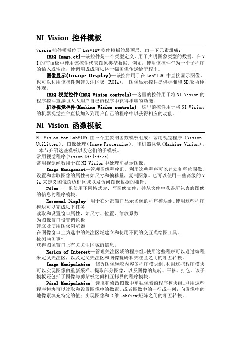
Vision II TM Plus ArrayS E R I E S C O N T R O L L E Rii1The following are brief descriptions of the Vision II Plus components and display elements. Each of these items will be explained in further detail within the appropriate programming, operating and installation sections of this guide.1- DisplayA-Week 1 and 2 identifiers – Shows the current week of a 14-day Calendar watering schedule.B -“Start Time” symbol – This symbol is dis-played when setting the program start times.C -Various time values and word prompts are dis-played here.D -Program A and B identifiers.E -“Watering On” symbol – This symbol is dis-played when a station is operating.F -“Watering Off” symbol – This symbol is dis-played when watering activity has been sus-pended by the (optional) Rain Switch.G -“Power Off” symbol – This symbol is dis-played when the main power source is discon-nected or the controller’s fuse is blown.H -“Percent” symbol – This symbol indicates theSeasonal Adjust feature is in use.I -Day abbreviations indicate the active wateringday schedule.J -“Run Time” symbol – This symbol is displayed when selecting the station run time.K -Number display identifies which station is cur-rently watering. The Interval watering schedulenumber (if used) is also displayed here.L-The current day of the week and various word prompts are displayed here.2-Program Start Time ControlsSlidingA and B.3- Advances the current day4-Clock Hour Button – Advances the clock run time mode from Minutes to Hours.5-Clock Minute Button – Advances therun time mode from Hours to Minutes.6-Cal / Int Button – Alternates the displaybetween the Calendar and Interval wateringschedules.7- SelectsProgram Aschedule.8-Select (+) Button – Selects the watering days ina Calendar day schedule and increases the Inter-val schedule number.9-Delete (–) Button – Removes watering days from a Calendar day schedule and decreases theInterval schedule number.10-Off/On Switch – Selects the controller operating mode. When switched On, the controller can beprogrammed and operated automatically or man-ually. When switched Off, all controller pro-gramming and operating features are disabled.11-Manually starts Program Awatering cycle.12-es the run time of all stations by the same amountfrom 20 to 200%.34Valve 1 Valve 4781011121314Setting an Interval Schedule1.Select Program A or B with theswitch.This example shows a 2-day Interval schedule (water every other day) set for Program A. The firstwatering day of the interval is today, Saturday.1.Turn the desired Station Run Time dial slowly to the right while viewing the display.1.Assign each active station to a program by placing its Station Control switch in the A or B position.1.Begin with all Program Start Time indicators set to the left (Off) position.2.Slide one indicator of either Program A or B to the right until the desired start time is displayed.3.Repeat step 2 for each program start time required.The display will revert to the current time and day after 5 seconds of inactivity. Setting the Program Start Time(s)Setting the Station Run Time161719202122232425s Internal Transformer Models:•Input Power: 120/230 V a.c., 50/60 Hz, 30V A •Output Power: 24 V a.c., 50/60 Hz, 22V A •Input Power: (Australia / New Zealand)240 V a.c., 50 Hz, 26V A•Output Power: (Australia / New Zealand)24 V a.c., 50 Hz, 15V As External Transformer Models:•Input Power – 120 V a.c., 60 Hz, 30V A •Output Power – 24 V a.c., 60 Hz, 30V As Maximum Station Output: 0.5A@ 24 V a.c.s Maximum Number of Plastic V alves Allowed Per Station: Two Toro 1" Electrics Maximum Pump Relay/Master V alve Output:0.5A@ 24 V a.c.s Maximum Output (Station and Pump/Master V alve): 0.9A@ 24 V a.c.Maximum Output (Australia / New Zealand) (Station and Pump/Master V alve): 0.7A@ 24 V a.c. s Fuse – 1.5A, 250V, Fast-Blows Plastic Cabinet Dimensions:•14" H x 10" W x 3" D•(35.6cm H x 25.4cm W x 7.6cm D)s Metal Cabinet Dimensions:•13-1/8" H x 8-3/4" W x 3-3/4" D•(33.3cm H x 22.2cm W x 9.5cm D)s Conduit Access:•1/2" (13mm) Power Wiring•1" (25mm) Field Wirings Battery Back-Up: 9V Rechargeable Ni-MH Domestic:This equipment generates and uses radio frequency energy and if not installed and used properly, that is, in strict accordance with the manufacturer's instructions, may cause interference to radio and television reception. It has been type tested and found to comply with the limits for a FCC Class B computing device in accordance with the specifications in Subpart J of Part 15 of FCC Rules, which are designed to pro-vide reasonable protection against such interference in a resi-dential installation. However, there is no guarantee that interference will not occur in a particular installation. If this equipment does cause interference to radio or television recep-tion, which can be determined by turning the equipment off and on, the user is encouraged to try to correct the interference by one or more of the following measures:•Reorient the receiving antenna.•Relocate the irrigation controller with respect to thereceiver.•Move the irrigation controller away from the receiver.•Plug the irrigation controller into a different outlet so that the irrigation controller and receiver are on different branch circuits.If necessary, the user should consult the dealer or an experi-enced radio/television technician for additional suggestions. The user may find the following booklet prepared by the Federal Communications Commission helpful:"How to Identify and Resolve Radio-TV Interference Problems". This booklet is available from the U.S. Government Printing Office, Washington, DC 20402. Stock No. 004-000-00345-4.International:This is a CSPR 22 Class B product.©1998 The Toro Company Irrigation DivisionAn ISO 9001-Certified Facility P.O. 489 Riverside, CA92502Form Number 371-0028 Rev. B(311-21321C)。
gige vision协议数据流控机制的分析与实现

• 113•GigE Vision协议提供了高性能工业相机数据通信的标准接口,本文基于GigE Vision协议设计并实现了一种流控机制,该机制主要作用于PC客户端,可满足相机发送端发送图像数据、图像信息或其他信息给接收端的需求,同时保证数据传输的高效可靠。
该机制在传输层上使用UDP协议,避免了传输层复杂的流控带来延迟,实现数据包的高速传输;在应用层上实现了GVCP控制协议和GVSP数据流协议两种不同的可靠传输机制,在连续高速采集数据的同时,能有效检测并处理丢包情况。
通过搭建ZC702相机开发板和PC客户端应用程序测试平台,连续发送多幅图像数据,采用Wireshark抓包软件分析并验证了该设计方案达到了100Mbps的平均吞吐量,能够满足可靠传输的要求并具有良好的实时性。
1.引言随着新一轮制造业的变革与科技革命的到来,制造业需要向智能化、数字化加快转变,工业生产中工业相机的应用顺应了这一时代潮流,通过工业相机将产品制造、物流、销售等各个环节加以控制,从而提升生产与工作效率,为了能够对相机进行实时控制以及数据获取,需要为管理软件和相机之间的通信提供可靠的数据传输机制。
常用的相机数据通信协议有GigE Vision、CoaXPress、Camera Link等等,GigE Vision协议基于UDP协议开发,是一种高性能工业相机接口标准,相比其他协议,它有更好的兼容性(吴远波,黄劼,辛军强,一种基于GigE Vision的多路图像采集系统设计:信息与电脑,2018),可以提供更长的传输距离,可以使用价格低廉的标准以太网线缆进行快速的数据通信(Thryft,Ann R.GigE Vision expand in machine vision:Test & Measurement World,2008)。
UDP协议是在网络层IP协议的基础上,增加了多路复用/分解和差错校验功能,所以只能为上层调用它的应用程序提供不可靠、无连接、基于数据报的服务(James F.Kurose,Keith puter Networking:A Top Down Approach:Boston:PEARSON Education,2013)。
(完整word版)VISION中文的使用说明
NI Vision 控件模板Vision控件模板位于LabVIEW控件模板的最顶层,由一下元素组成:IMAQ Image.ctl—该控件是一个类型定义,用于声明图象类型的数据。
在V I的前面板中使用该控件代表图象类型数据。
例如,使用该控件作为一个子程序的输入或输出,使调用成成可以将一幅图像传送给子程序。
图像显示(Image Display)—该控件用于在LabVIEW 中直接显示图像。
也可以利用该控件创建关注区域 (ROIs)。
图像显示控件提供标准和3D版两种外观。
IMAQ 视觉控件(IMAQ Vision controls)—这里的控件用于将NI Vision的程序控件直接加入入用户自己的程序中获得相应的功能。
机器视觉控件(Machine Vision controls)—这里的控件用于将NI Vision 的机器视觉控件直接加入到用户自己的程序中以获得相应的功能。
NI Vision 函数模板NI Vision for LabVIEW 由三个主要的函数模板组成:常用视觉程序(Vision Utilities), 图像处理(Image Processing), 和机器视觉(Machine Vision)。
本节介绍这些模板以及它们的子模板。
常用视觉程序(Vision Utilities)常用视觉函数用于在NI Vision中处理和显示图像。
Image Management—管理图像程序组。
利用这些程序可以建立和释放图像,设置和读取图像的属性例如尺寸和偏移量,复制图象。
也可以使用一些高级的V is来定义图像的边框区域以及访问图像数据的指针。
Files—一组使用不同格式读、写图像文件,并从文件中获得所包含的图像的信息的程序模块。
External Display—用于在外部窗口显示图像的程序模块组。
使用这些程序模块可以完成以下任务:读取和设置窗口属性,如尺寸、位置、缩放系数为图像窗口设置调色板建立及使用图像浏览器在图像窗口上为选中的关注区域建立和使用不同的交互式绘图工具。
如何使用GigE Vision相机抓拍图像

本文档用于说明PC机第一次和相机相连的设置
1.确保相机和电脑之间通过千兆网线相连,之间经过的网线接头、交换机越少越好。
2.在电脑上安装有LabVIEW和VDM、VAS。
3.关闭windows自带防火墙、360防火墙、杀毒一类软件。
4.打开网卡的巨大帧功能。
右键我的电脑,管理,设备管理器,网络适配器,选择网卡,
右键,属性,高级,属性,巨型帧,更改值为最大,一般为9KB MTU。
如果网卡不支持巨帧,可以尝试调小网络包的大小。
在Max中,点击相机,在获取属性中,更改包大小,可以尝试更改为2000或者1000.
5.使用相机自带的软件先进行测试。
a)把相机的IP地址设至为与电脑同一IP段。
即IP地址前三位一样。
b)采集连续图像。
6.在Max中查看已经连接好的相机,如果没有安装相机本身的驱动,连接了一个相机就
会有一个相机,如果安装了驱动,会有N+1个相机,
7.使用抓拍标定图像.VI来抓拍图像。
1、选择正确的相机2、选择想要保存的基础路径3、
运行vi。
杰士安720P高清网络球形摄像机_WEB2.0操作手册

杰士安高清网络球形摄像机使用说明书V2.0在使用网络摄像机之前,敬请您仔细阅读本操作手册声明本手册可能在某些技术细节方面描述不够准确或存在印刷错误,假如您在使用过程中按照使用手册无法解决问题时,请致电我公司技术部垂询相关操作方法。
本手册的内容将做不定期的更新,恕不另行通知。
使用注意事项1、安装环境,安装时请参照设备的环境要求,不要在过于潮湿、多尘和多烟灰的地点安装此设备;,应使设备远离振动或存在磁场干扰的地点;,如希望改变已安装设备的位置,请确保电源关闭后再移动或重新安装。
,如果设备发出不正常的气味或烟雾,应立即停止使用,并切断电源,之后与供货商联系;,清洁设备时,不要直接将水溅在设备部件上;,避免将设备放置在热源附近;,不要将摄像机瞄准强光物体,无论是使用中或非使用中,绝不可以使其瞄准太阳或其它的光亮物体,否则可能造成摄像机CCD永久受损;,禁止在易燃、易爆的危险区域存储、安装和使用本产品。
2、运输与搬运,本机的包装经过抗震设计和实验,确保在运输过程中设备不会受到意外损坏,所以在搬运本机时,最好使用原来的包装材料和纸箱;,避免在过冷、过热的场所间相互搬动设备,以免机器内部产生结露,影响机器的使用寿命;,严禁带电搬动本机,否则会导致设备部件损坏。
目录一. 产品简介............................................................................- 2 -前言................................................................................- 2 -1.1应用领域........................................................................- 2 -1.2产品特性........................................................................- 2 -1.3技术规格........................................................................- 3 -1.4使用环境........................................................................- 4 -二. 外观与安装..........................................................................- 5 -2.1网络球机外观及规格..............................................................- 5 -2.2网络球机连接线示意图............................................................- 5 -三. 搜索设备及控件下载安装..............................................................- 6 -3.1搜索设备及修改网络参数...........................................................- 6 -3.2检查连接........................................................................- 7 -四. IE浏览器登陆......................................................................- 10 -4.1系统设置.......................................................................- 15 -4.1.1系统设置.................................................................- 16 -4.1.1.1【普通设置】........................................................- 16 -4.1.1.2【编码设置】........................................................- 17 -4.1.1.3【录像设置】........................................................- 17 -4.1.1.4【抓图设置】........................................................- 17 -4.1.1.5【串口设置】........................................................- 18 -4.1.1.6【网络设置】........................................................- 18 -4.1.1.7【云台设置】........................................................- 23 -4.1.1.8【配置/默认】.......................................................- 23 -4.1.2报警功能.................................................................- 24 -4.1.2.1【报警输入】........................................................- 24 -4.1.2.2【动态检测】........................................................- 24 -4.1.2.3【报警输出】........................................................- 25 -4.1.2.4【异常处理】........................................................- 25 -4.1.3高级选项.................................................................- 26 -4.1.3.1【存储设备管理】....................................................- 26 -4.1.3.2【 升 级 】........................................................- 26 -4.1.3.3【录像控制】........................................................- 27 -4.1.3.4【用户账户】........................................................- 27 -4.1.3.5【自动维护】........................................................- 28 -4.2 网络球机云台控制操作...........................................................- 28 -4.2.1预置点...................................................................- 30 -4.2.2预置点扫描...............................................................- 30 -4.2.3区域扫描.................................................................- 30 -4.2.4花样扫描.................................................................- 31 -4.2.5巡航组...................................................................- 31 -一. 产品简介前言感谢您使用本公司网络球机系列,该系列是针对网络视频监控而开发的一体化网络球机。
GigE Vision 2.0说明书

目錄引言 (1)第1章設備發現 (2)1.1 鏈路選擇 (2)1.2 IP位元址配置 (3)1.3 設備枚舉 (3)1.4 設備添加與刪除 (4)第2章 GVCP協議 (5)2.1 基本概念 (5)2.2 通道 (5)2.3 其他 (11)第3章引導寄存器 (14)3.1 引導寄存器 (14)3.2 相機的標準特徵表 (22)引言GigE Vision 是一種通信介面標準,可用於各種網路拓撲上的視覺軟體與視頻流設備間的交互。
該標準是基於UDP/IP協議體系,並構成了Gige Vision 協議(工作在應用層,包括GVCP和GVSP兩個協議)。
需要的設備包括IP網路上各種軟硬體攝像機、處理器、路由器等。
本說明中,設備指的是一個GigE Vision相容的可控設備,而應用程式指運行在一台主機上的一個與GigE Vision相容的控制程式。
本說明分三部分,即設備發現、GVCP協定和引導寄存器,分別在對應的章節中介紹。
第1章設備發現PC在接入設備時,需要一種機制發現設備,即鏈路選擇、IP位址配置、設備枚舉。
1.1 鏈路選擇設備在接入PC後,需要確定所有通信鏈路哪些是可用的,然後與PC端協調選擇相應速率的鏈路。
共提供了4種不同類型的物理鏈路配置:①單鏈路配置SL②多鏈路配置ML③靜態鏈路聚合組配置sLAG④動態鏈路聚合組配置dLAG其中,頭2個配置中,每個物理鏈路介面都有1個不同的IP位址;對於後2個配置,物理介面經過重組後,只有1個IP位址在程式中可見,物理鏈路的分組在MAC層執行,對於應用軟體是透明的。
1.1.1 單鏈路配置最簡單的配置,所有的流通道加到一個有效物理鏈路上,所有設備必須支援SL配置。
1.1.2 多鏈路配置一個設備必須最多支援4個不同的網路介面。
介面#0(唯一支援GVCP)為主介面來控制設備的控制與消息通道,如設備發現總是在#0上執行,以確保設備使用不同的IP位址而不被多次發現。
其他介面只支援附加的流通道,如發送或接收GVSP資料包。
The Imaging Source GigE相机设备驱动及软件开发工具包说明书

Device Drivers for Microsoft WindowsDevice Driver for The Imaging Source GigE Cameras.Software Development Kits (SDKs) for Microsoft Windows IC Imaging Control .NET Component for C#, , C++ Class Library for C++ projects, IC Imaging Control C Library, IC Imaging Control ActiveX, IC Imaging Control ActiveX Runtime Setup.Extensions for Microsoft WindowsTWAIN Source for IC Imaging Control, Cognex VisionPro AIK Plugin for IC Imaging Control, ActivVisionTools Driver for IC Imaging Control, HALCON Extension for IC Imaging Control, LabVIEWExtension for IC Imaging Control, IC Matlab Plugin for Matlab 10.0R2010, IC Matlab Plugin for Matlab R2013b and R2014, IC NeuroCheck Driver for NeuroCheck 6.0, IC NeuroCheck Driver for NeuroCheck 6.1.End User Software for Microsoft WindowsIC Capture, Image Acquisition, IC Measure, manual on-screen image measurement and image acquisition, IC Fullscreen Presenter, IC Line Profiler, Footswitch software for IC Capture, Scan2Docx, Scan2Docx OCR, Scan2Voice.The Imaging Source authors and supports drivers, SDKs, extensions and end-user software for Microsoft Windows, which can be freely downloaded from our web site. Extensions for Microsoft Windows enable the DMK 33GX236 to be integrated in to common machine vision software libraries, such as LabView and OpenCV. Furthermore, we author and support open source Linux drivers and software (Apache License 2.0) to integrate the camera into popular distributions. Download the Linux source code at patible to C and CS mount lenses.Casing compatible to Sony footprint.(shipped as standard).Standard GigE cable in various lengths.DMK 33GX236 SpecificationVideo formats @ frame rate1,920x1,200 (2.3 MP), Y800 @ 50 (max) FPS1,920x1,200 (2.3 MP), Y16 @ 25 (max) FPS Sensitivity0.05 lxDynamic range8 / 12 bitIR cut filter noSensor specificationSony IMX236LLShutter RollingFormat/ "Resolution H: 1,920 pixel, V: 1,200 pixelPixel size H: 2.8 µm, V: 2.8 µmLens mount C/CSInterface GigESupply voltage11 VDC to 13 VDC or PoE: 48 VDC to 56 VDC Current consumption approx 400 mA at 12 VDCDimensions H: 29 mm, W: 29 mm, L: 57 mmMass65 gShutter20 µs s to 30 sGain0 dB to 48 dB12.8Sony IMX236LL Spectral Response CurveExmor Sensor in DMK 33GX236Wavelength [nm]R e l a t i v e R e s p o n s eMachine Vision - Designed in GermanyEver since The Imaging Source was founded in 1990, it has been one of the leadingmanufacturers of industrial cameras, frame grabbers and video converters forautomation, quality assurance, logistics, medicine, science and security.Our extensive range of industrial cameras ships with USB 3.0, USB 2.0, GigE, FireWire 800 and FireWire 400 interfaces. Thanks to their multi-purpose features and extremely high quality standards, the cameras are commonly used in demanding applications.The software support offered by the cameras fulfill the requirements of demanding end-users and programmers. The cameras can be put into operation within a few minutes, or integrated into new or existing applications with only a few lines of code. All camera drivers are Microsoft certified. The easy of which the cameras can be integrated, the corresponding low integration costs, and the high quality of the software set the industry standard.All cameras, frame grabbers and video converters, manufactured by The Imaging Source, are the result of decades of experience, uncompromisingly high quality standards, and continual development. Developers and system engineers prefer The Imaging Source cameras due to their ease of system integration.World-Class Software and Customer CareWhat really separates The Imaging Source from its competitors is the comprehensive Windows and Linux software available free of charge with all its products, and the The Imaging Source authors and supports device drivers, software development kits (SDKs), programmingUSA European Asian HeadquartersPRESENT ALL OVER THE WORLD.Taipei City 114, Taiwan.All product and company names in this document may be trademarks and tradenames of their respective owners and are hereby acknowledged. The Imaging Source, LLC cannot and does not take any responsibility or liability for any information contained in this document. The source code in this document may be used exclusively used for educational purposes. The Imaging Source,LLC does not assume any kind of warranty expressed or implied, resulting from the use of the content of this document or the source code. The Imaging Source, LLC reserves the right to makechanges in specifications, function or design at any time and without prior notice.All weights and dimensions are approximate. Unless otherwise specified the lenses shown in the context of cameras are not shipped with these cameras.Reprint, also in parts, only allowed with permission of The Imaging Source, st update: April 19, 2016 at 2:36 PM. © 2016 The Imaging Source, LLC. All rights reserved.。
AGM Global Vision 夜视双目望远镜用户手册说明书

© 2023 AGM Global Vision, LLC. All rights reserved.This documentation is subject to change without notice.No parts of this manual, in whole or in part, may be copied, photocopied, translated, or transmitted by any electronic medium or in machine-readable form without the prior written permission of AGM Global Vision, LLC.If you have questions that are not covered in this manual, or need service, contact AGM Global Vision customer support for additional information prior to returning a product.AGM Global Vision, LLC173 West Main StreetPO Box 962Springerville, AZ 85938Tel. 928.333.4300***************************EXPORT INFORMATIONBuyer acknowledges that all products supplied by AGM Global Vision, LLC are subject to U.S. export control laws, including, but not limited to, the Export Administration Regulations, the International Traffic in Arms Regulations, the International Economic Emergency Powers Act, and various U.S. embargoes and sanctions. AGM Global Vision products may not be exported, re-exported, or transferred contrary to U.S. export control laws. In particular, AGM Global Vision products may not be exported, re-exported, or transferred to prohibited countries, individuals, organizations, or entities, including but not limited to those individuals and entities listed on the List of Specially Designated Nationals and Blocked Persons administered or maintained by the U.S. Office of Foreign Assets Control (“OFAC”), the various lists maintained by the Bureau of Industry and Security of the Department of Commerce, and the U.S. State Department and Buyer represents and warrants that neither Buyer nor any of its officers, directors, or employees are on such lists. Distribution or resale by Buyer to such countries, individuals, organizations, or entities is expressly prohibited. Buyer has and will maintain a positive process to ensure compliance with this Section.2023.01.09LIST OF CONTENTSTITLE PAGE Safety Summary 4 SECTION 1. GENERAL INFORMATION6 1.1 System Description 6 1.2 Standard Components and Optional Equipment 7 1.3 Key Features 8 SECTION 2. OPERATING INSTRUCTIONS 9 2.1 Installation and mounting 9 2.2 Controls and Indicators 11 2.3 Operating Procedures 12 SECTION 3. MAINTENANCE INSTRUCTIONS 14 3.1 Cleaning Procedures 14 3.2 Troubleshooting 14 3.3 Preparation for Extended Storage 15 SECTION 4. WARRANTY INFORMATION 16 4.1 Warranty Information and Registration 16 SECTION 5. SPECIFICATIONS 18 5.1 Specifications 18FoxBat USER MANUAL3SAFETY SUMMARY• Read and follow all instructions• Read all warnings• Only use the attachments/accessories specified by the manufacturer• All maintenance must be done by the manufacturerWARNING:This product contains natural rubber latex, which may cause potentially fatal allergic reactions! If you are allergic to latex, it is important that you strictly avoid exposure to products that contain it.WARNING:The intensifier’s phosphor screen contains toxic materials.Please note:• If the intensifier tube breaks, be extremely careful to avoid inhaling the phosphor screen material. DO NOT allow the material to come in contact with your mouth, eyes, or any open wounds on the skin.• If the phosphor screen material comes in contact with your skin, wash it off immediately with soap and water.• If you inhale or swallow any phosphor screen material, drink a lot of water, induce vomiting, and seek medical attention as soon as possible.WARNING:• When used in total darkness, the light from the unit’s infrared (IR) illuminator is invisible to the naked eye. However, the light can be detected by other Night Vision Devices (NVD).• To reduce the risk of detection by another NVD, avoid prolonged use of the IR illuminator.• Light from the IR illuminator is more easily detected by other NVDs when used in fog, smoke, and rain. Avoid prolonged use of the IR illuminator in these conditions.• Do not use contaminated eyecups. If it is contaminated, it must be replaced.4AGM Global VisionCAUTIONS:The FoxBat night vision bi-ocular is a precision electro-optical instruments and require careful handling. Please follow the below instructions of safe use:• Do not disassemble the unit.• Keep the unit clean; protect it from moisture, sudden temperature drops and shocks.• Be careful not to touch the glass surfaces. If you leave fingerprints on, or contaminate the glass surfaces, use only clean and soft materials to clean it.• Protect the unit from excessive lighting. Do not turn the bi-ocular on in daylight with the front lens cap off. Do not point the bi-ocular at the bright light source (a fire, car headlights, lanterns, street lamps, room lights, etc.).• Do not test the device in daylight conditions even with the daylight filter/lens cap on for more than ten (10) minutes.• Do not leave the unit in the ON position during breaks in operation.• Remove the battery from the unit when it will be stored for more than 3 days. Failure to do so may damage the unit.EQUIPMENT LIMITATIONSTo avoid injuries and equipment damage from using the FoxBat, carefully read and consider the following equipment limitations.• The equipment requires some night light (moonlight, starlight, etc.) to operate. The level of equipment performance depends upon the level of light.• The amount of night light is reduced when passing through the clouds, while operating under trees, under the shadows of houses, etc.• The device is less effective when peering into shadows and other darkened areas.• The device is less effective in viewing through rain, fog, sleet, snow or smoke.• The equipment will not “see” through dense smoke.• Its protection system cuts off the image intensifier when ambient light level continues to exceed of 40 lux for 10 seconds or more.• Under starlight conditions, low contrast environments (such as snow-covered territory, sandy deserts, large bodies of water or grassy hills) degrade visibility thereby disguising or masking changes in terrain.• Under too low-light conditions the device loses some of the resolution it has under full moon conditions.FoxBat USER MANUAL56AGM Global Vision1.1 SYSTEM DESCRIPTIONThe FoxBat night vision bi-ocular is the perfect tool for mid-range and long-range observation. The FoxBat combines a single high quality image intensifier tube with a dualized optical axis and double eyepiece, making it applicable for long viewing sessions. The FoxBat is available in two configurations - 5x and 8x magnification. This night vision bi-ocular is the ideal choice for security and recreational use.FIGURE 1-1. FOXBAT SERIESFOXBAT-5FOXBAT-8FIGURE 1-2. FOXBAT MAIN PARTS7FoxBat USER MANUALTABLE 1-1. FOXBAT SYSTEM DESCRIPTION1.3 STANDARD COMPONENTS & OPTIONAL EQUIPMENTThe standard components and optional equipment of the FoxBat are shown in Figure 1-3 and listed in Table 1-2.The ITEM column indicates the number used to identify items in Figure 1-3.TABLE 1-2. FOXBAT STANDARD COMPONENTSFIGURE 1-3. FOXBAT STANDARD COMPONENTS1.3 KEY FEATURES• 5x or 8x Magnification• Biocular optical system for long-term observation• Super-fast, multi-coated, all-glass optics• Rugged and versatile design• Waterproof• Ergonomic, simple, easy-to-operate controls• High-light overload protection• Auto brightness control• Long-range Infrared illuminator• Tipod mountable• Limited 3-year warranty8AGM Global Vision9FoxBatUSER MANUAL 2.1. INSTALLATION AND MOUNTINGCAUTION:To protect the intensifier tube when the sight is not in use or when it is being operated in daylight, keep the protective lens cap securely fitted over the lens.2.1.1 BATTERY INSTALLATIONTo install batteries:1. Turn the battery cap counterclockwise and remove it.2. Verify that the O-ring is present. If it’s not, replace it.3. Following the polarity markings on the outside of the battery compartment, insert two AA (1.5V) batteries into the battery compartment, positive (+) end first (see Figure 2-1).4. Secure the battery cap back on by placing it over the compartment and turning it clockwise. Verify that it is secure to ensure a watertight seal.2.1.2 INSTALLATION OF THE EYECUPSTo install the eyecups (refer to Figure 2-1):1. Carefully press each eyecup over the diopter cell retainer.2. Rotate each eyecup into the proper viewing position. Adjust for the best fit. The eyecups must seal around your eyes and prevent the green light from showing outside of the eyepieces.FIGURE 2-1. BATTERY AND EYE CAP INSTALLATION10AGM Global Vision2.1.3 TRIPOD INSTALLATIONFoxBat bi-ocular can be used on the tripod.To install FoxBat-5 on tripod, install Tripod Adapter first. Tighten the screw of tripod it in the 1/4” threaded socket of Tripod Adapter.To install FoxBat-8 on tripod, tighten the screw of tripod in the 1/4” threaded socket of bottom Picatinny rail of FoxBat-8.NOTE:The unit may be badly damaged if the tripod collapses or falls over. Remove the unit from the tripod if it is not within your reach.2.1.4 INFRARED ILLUMINATOR INSTALLATIONThe Infrared Illuminator is delivered ready-assembled with a dedicated mount, to be installed on Picatinny rail. To install IR illuminator to FoxBat-5, install IR Adapter first.FOXBAT-5FOXBAT-8FOXBAT-5FOXBAT-8FIGURE 2-3. IR ILLUMINATOR INSTALLATION11FoxBat USER MANUAL Refer to Figure 2-3 and complete the following steps: 1. Loosen the fixing screw of the IR Illuminator mount.2. Mount the IR illuminator on the rail. The recoil stop of the IR Illuminator mount should fit into the transverse slot of the rail.3. Tighten the fixing screwof the IR Illuminator mount.2.2 CONTROLS AND INDICATORS2.2.1 CONTROLS AND INDICATORSThe FoxBat is adjustable to accommodate different users and will correct for most differences in eyesight. The controls and indicators for the FoxBat are shown or described in Figure 2-4 and Table 2-1.TABLE 2-1. CONTROLS AND INDICATORS12AGM Global Vision2.3 OPERATING PROCEDURES2.3.1 OPERATING PROCEDURES1. Verify that the batteries are installed properly.CAUTION:Only operate the Bi-Ocular in dark environments. If it necessary to operate the device in daylight, always cover the objective lens with the lens cap. The pinhole at the centre of the lens cap will allow the user to check operational capabilities in daylight conditions.2. Remove the lens cap.3. Turn the function switch to the ON position. Power LED indicator in field of view will lights up. After a slight delay, a green or white glow will appear in the eyepiece of the unit.4. Adjust the interpupillary distance by sliding the eyepieces together or apart so that each eye can observe the entire field of view at the same time. The eyepieces adjust independently.5. Observe the scene. Adjust the diopter by rotating the adjustment rings.6. Adjust the focus. Rotate the focus ring until the image is clear and sharp.NOTE:The sharpest image will only be visible when the objective lens and eyepiece lens are both properly focused.If the bright light cut-off feature turns the device off, you need turn it back on manually after 1~2 minutes once the light in the surrounding environment decreases to an acceptable level, or the device is remitted to a darker area. To turn on the device again, set the operating switch to the OFF position and then turn it to the ON position.2.3.3 OPERATING UNDER CHANGING LIGHT CONDITIONSIf the ambient light level exceeds 40-100 Lux for more than 10 seconds, the automatic protective system will shut off the intensifier tube. If an operation must be carried out in changing light conditions, the user can shut down the protective system manually by closing the photoreceiver. CAUTION:DO NOT forget to open the photoreceiver after completing your mission.2.3.2 LONG-RANGE INFRARED ILLUMINATOR OPERATIONSCAUTION:• The device is equipped with an infrared LED which is not hazardous to human health. However, do not point the IR illuminator at anyone’s eyes.• The IR illuminator infrared light will be invisible to the naked eye. The light can, however, be detected by other night vision devices.To operate the IR illuminator:1. Install the IR illuminator per the instructions in Paragraph2.1.4.2. Turn on the IR illuminator by pressing the tail cap button.3. The IR illuminator has 3 power modes, changed with a tail button. Press the tail button to turn the IR light ON. Continue to press to change the power modes. There are 3 power modes in cyclic sequence (OFF - Low Power ON - OFF - Middle Power ON - OFF - High Power ON - OFF).4. To adjust IR beam divergence, rotate the objective lens.5. To turn off the IR illuminator press the tail cap button again.2.3.2 FOXBAT SHUTDOWN1. Turn the function switch to the OFF position. The green glow of the viewing area will fade to black.2. Secure the lens cap over the objective lens.3. If necessary, remove the long-range IR illuminator.4. Unscrew the battery cap and remove the batties. Replace the battery cap. Do not store the unit with the batteries installed.5. Store the unit and all accessories in the case.FoxBat USER MANUAL1314AGM Global Vision3.1 CLEANING PROCEDURESWipe the housing with a damp cloth as needed. CAUTION:Do not use abrasives or solvents to clean the housing, lens, or the display window of the device. Do not use ammonia-based cleaning products to clean the lens. Doing so may damage the anti-reflective coating of the lens. Doing so may damage the anti-reflective coating on the lens.The FoxBat lens is designed for the harsh outdoor environment and has a coating for durability and anti-reflection, but it may require occasional cleaning. Avoid scratching the lens and/ or leaving fingerprints on the lens. Optics can be damaged by improper cleaning. Clean the lens according to the instructions below.Do not use abrasive materials, such as paper towels or scrub brushes to clean lens, as this can scratch or otherwise damage the lens. Only clean when there is visible contamination on the surface.Preferred Method for Cleaning the Lens Materials:• Optical-grade cloth• Pure water (deionized or other)• Isopropyl alcohol (IPA)Saturate a piece of the lens cloth with water and drape it over the lens. Let the surface tension of the water pull the cloth onto the lens surface. Drag the cloth across the lens surface. Repeat several times with different pieces of cloth.Repeat the same steps using isopropyl alcohol instead of water. Drag the final piece of tissue over the lens several times to prevent pooling, which may leave a residue behind.3.2 TROUBLESHOOTINGTable 3-1 lists the most common malfunctions that may occur with your device. Perform the tests, inspections, and corrective actions in accordance with the instructions given in the table.This table does not list all the malfunctions that may occur with your device, or all of the tests, inspections, and corrective actions that may be necessary to fix them. If the equipment malfunction is not corrected by the suggested actions, or a problem occurs that is not listed in this table, please contact AGM Global Vision’s Customer Support center or your retailer.3.3 PREPARATION FOR EXTENDED STORAGE1. Unscrew the battery cap and remove the batteries from the Bi-Ocular.2. Inspect the battery compartment for corrosion or moisture. Clean and dry if necessary.3. Replace the battery cap.4. Remove the long-range IR illuminator, if installed.5. Ensure that the bi-ocular, accessories and case are free of dirt, dust, and moisture.6. Place the bi-ocular and accessories into the carrying case.15FoxBat USER MANUAL16AGM Global Vision4.1 WARRANTY INFORMATION AND REGISTRATION4.1.1WARRANTY INFORMATIONThis product is guaranteed to be free from manufacturing defects in material and workmanship under normal use for a period of three (3) years from the date of purchase. In the event that a defect covered by the warranty below occurs during the applicable period stated above, AGM Global Vision, at its discretion, will either repair or replace the product; such action on the part of AGM Global Vision shall be the full extent of AGM Global Vision’s liability, and the Customer’s sole and exclusive reparation. This warranty does not cover a product if it has been (a) used in ways other than its normal and customary manner; (b) subjected to misuse; (c) subjected to alterations, modifications or repairs by the Customer or by any party other than AGM Global Vision without prior written consent of AGM Global Vision; (d) is the result of a special order or categorized as “close-out” merchandise or merchandise sold “as-is” by either AGM Global Vision or the AGM Global Vision dealer; or (e) merchandise that has been discontinued by the manufacturer and either parts or replacement units are not available due to reasons beyond the control of AGM Global Vision. AGM Global Vision shall not be responsible for any defects or damage that in AGM Global Vision’s view are a result from the mishandling, abuse, misuse, improper storage or improper operation of the device, including use in conjunction with equipment that is electrically or mechanically incompatible with, or of inferior quality to, the product, as well as failure to maintain the environmental conditions specified by the manufacturer. This warranty is extended only to the original purchaser. Any breach of this warranty shall be enforced unless the customer notifies AGM Global Vision at the address noted below within the applicable warranty period.The customer understands and agrees that except for the foregoing warranty, no other warranties written or oral, statutory, expressed or implied, including any implied warranty of merchantability or fitness for a particular purpose, shall apply to the product. All such implied warranties are hereby and expressly disclaimed.4.1.2 LIMITATION OF LIABILITYAGM Global Vision will not be liable for any claims, actions, suits, proceedings, costs, expenses, damages, or liabilities arising out of the use of this product. Operation and use of the product are the sole responsibility of the Customer. AGM Global Vision’s sole undertaking is limited to providing the products and services outlined herein in accordance with the terms and conditions of this Agreement. The provision of products sold and services performed by AGM Global Vision to the Customer shall not be interpreted, construed, or regarded, either expressly or implied, as being for the benefit of or creating any obligation toward any third party of legal entity outside AGM Global Vision and the Customer; AGM Global Vision’s obligations under this Agreement extend solely to the Customer. AGM Global Vision’s liability hereunder for damages, regardless of the form or action, shall not exceed the fees or other charges paid to AGM Global Vision by the customer or customer’s dealer. AGM Global Vision shall not, in any event, be liable for special, indirect, incidental, or consequential damages, including, but not limited to, lost income, lost revenue, or lost profit, whether such damages were foreseeable or not at the time of purchase, and whether or not such damages arise out of a breach of warranty, a breach of agreement, negligence, strict liability, or any other theory of liability.4.1.3 PRODUCT REGISTRATIONIn order to validate the warranty on your product, the customer must complete and submit AGM Global Vision PRODUCT REGISTRATION FORM on our website (/ customer-support).4.1.4 OBTAINING WARRANTY SERVICETo obtain warranty service on your unit, the End-user (Customer) must notify the AGM Global Vision service department via e-mail. Send any requests to *************************** to receive a Return Merchandise Authorization number (RMA). When returning any device, please take the product to your retailer, or send the product, postage paid and with a copy of your sales receipt, to AGM Global Vision’s service center at the address listed above. All merchandise must be fully insured with the correct postage; AGM Global Vision will not be responsible for improper postage or merchandise that becomes lost or damaged during shipment. When sending product back, please clearly write the RMA# on the outside of the shipping box. Please include a letter that indicates your RMA#, the Customer’s Name, a Return Address, reason for the return, contact information (valid telephone numbers and/or an e-mail address), and proof of purchase that will help us to establish the valid start date of the warranty. Product merchandise returns that do not have an RMA# listed may be refused, or a significant delay in processing may occur. Estimated Warranty service time is 10-20 business days. The End-user/Customer is responsible for postage to AGM Global Vision for warranty service. AGM Global Vision will cover return postage/ shipping after warranty repair to the End-user/Customer only if the product is covered by the aforementioned warranty. AGM Global Vision will return the product after warranty service by domestic UPS Ground service and/or domestic mail. Should any other requested, required, or international shipping methods be necessary, the postage/shipping fee will be the responsibility of the End-user/Customer.For service, repair or replacement, please contact:AGM Global Vision, LLC173 West Main StreetPO Box 962Springerville, AZ 85938Tel. 928.333.4300***************************FoxBat USER MANUAL1718AGM Global Vision5.1 SPECIFICATIONSTABLE 5-1. FOXBAT BI-OCULAR SPECIFICATIONSTABLE 5-2. LONG-RANGE IR ILLUMINATOR SPECIFICATIONSNOTE:All data is subject to change without notice.FoxBat USER MANUAL19。
- 1、下载文档前请自行甄别文档内容的完整性,平台不提供额外的编辑、内容补充、找答案等附加服务。
- 2、"仅部分预览"的文档,不可在线预览部分如存在完整性等问题,可反馈申请退款(可完整预览的文档不适用该条件!)。
- 3、如文档侵犯您的权益,请联系客服反馈,我们会尽快为您处理(人工客服工作时间:9:00-18:30)。
目錄引言 (1)第1章設備發現 (2)1.1 鏈路選擇 (2)1.2 IP位元址配置 (3)1.3 設備枚舉 (3)1.4 設備添加與刪除 (4)第2章 GVCP協議 (5)2.1 基本概念 (5)2.2 通道 (5)2.3 其他 (11)第3章引導寄存器 (14)3.1 引導寄存器 (14)3.2 相機的標準特徵表 (22)引言GigE Vision 是一種通信介面標準,可用於各種網路拓撲上的視覺軟體與視頻流設備間的交互。
該標準是基於UDP/IP協議體系,並構成了Gige Vision 協議(工作在應用層,包括GVCP和GVSP兩個協議)。
需要的設備包括IP網路上各種軟硬體攝像機、處理器、路由器等。
本說明中,設備指的是一個GigE Vision相容的可控設備,而應用程式指運行在一台主機上的一個與GigE Vision相容的控制程式。
本說明分三部分,即設備發現、GVCP協定和引導寄存器,分別在對應的章節中介紹。
第1章設備發現PC在接入設備時,需要一種機制發現設備,即鏈路選擇、IP位址配置、設備枚舉。
1.1 鏈路選擇設備在接入PC後,需要確定所有通信鏈路哪些是可用的,然後與PC端協調選擇相應速率的鏈路。
共提供了4種不同類型的物理鏈路配置:①單鏈路配置SL②多鏈路配置ML③靜態鏈路聚合組配置sLAG④動態鏈路聚合組配置dLAG其中,頭2個配置中,每個物理鏈路介面都有1個不同的IP位址;對於後2個配置,物理介面經過重組後,只有1個IP位址在程式中可見,物理鏈路的分組在MAC層執行,對於應用軟體是透明的。
1.1.1 單鏈路配置最簡單的配置,所有的流通道加到一個有效物理鏈路上,所有設備必須支援SL配置。
1.1.2 多鏈路配置一個設備必須最多支援4個不同的網路介面。
介面#0(唯一支援GVCP)為主介面來控制設備的控制與消息通道,如設備發現總是在#0上執行,以確保設備使用不同的IP位址而不被多次發現。
其他介面只支援附加的流通道,如發送或接收GVSP資料包。
只能在#0中使用FORCEIP消息,其他介面必須使用靜態IP、DHCP或LLA來獲取其IP配置資訊。
可以認為ML配置中的一個連結就是一個LAG。
若支援多鏈路配置,必須在SCPx寄存器中指定流通道使用的具體介面,其network_interface_index欄位在流通道與網路介面間提供了映射機制,如果映射採用硬編碼,則該欄位唯讀。
允許將每個網路介面視為一個不同的GigE Vision設備,則每個介面是獨立的且具有合適的資源,這等價於將多個設備組合成一個單元。
負載平衡:網際協定IP會設計好一個路由使資料包到達接收端的正確介面上。
在ML中,為達到負載平衡,可分別將多個流通道一一關聯到不同的鏈路,以平衡這些鏈路所需的整體網路頻寬。
1.1.3 鏈路聚合組配置LAGIEEE 802.1AX標準規範了LAG的相關特性。
該標準下的電纜乙太網交換機遵守IEEE規範,這樣可能不會平衡負載GEV流輸送到多個外向埠上,這些埠通常使用Ethernet幀的頭部資訊(有時為IP頭)來作為其分配演算法的輸入參數,這些交換機在GVSP中是不可見的。
由於LAG顯示單個MAC/IP,這些交換機不能指出怎樣去分配GVSP輸送,可能在某交換機的一個外向埠上就停止輸送了。
網路介面:只允許有一個聚合器,因此,所有與LAG關聯的活動連結均綁定到該聚合器上。
若支援鏈路聚合配置,設備只允許靜態和動態LAG兩個配置中有一個聚合器,且其應該使用與LAG相關的具有最小編號物理網路介面的MAC位址。
故在引導寄存器中,只有一個“虛擬”網路介面可見。
GVCP影響:一個GVCP通道必須總是在LAG同一物理鏈路上被發送。
GVSP影響:定義比較寬鬆,使用round-robin分配演算法平衡網路負載。
首個流資料包可以在該聚合器的任意介面上傳送,也可在新的資料塊邊界上重啟一個round-robin新迴圈。
靜態LAG和動態LAG:兩者唯一區別在於IEEE 802.1AX的LACP協定的使用。
靜態LAG用於增加流的有效頻寬,假定這些鏈路的所有電纜走向同一目的地(如多埠NIC);但如果佈線不正確,LACP協定用來確保系統能正確綁定屬於同一互連的物理鏈路,對於動態LAG,其保證了一個聚合器中所有連結都在同一夥伴間。
LAG事件:由於聚合組中的一個物理鏈路連接上或斷開,而引起聚合速度改變時,設備應發送一個GEV_EVENT_LINK_SPEED_CHANGE事件。
1.2 IP位址配置該過程即分配一個IP位址給設備。
GigE Vision設備支援DHCP、LLA和靜態IP(可選)三種方式分配IP。
該配置在設備啟動或重啟時執行。
1.2.1 協議選擇每個IP配置協定的執行順序必須是靜態IP(若支援並啟用)、DHCP(若啟用)和LLA。
出廠預設靜態IP禁用,DHCP啟用,LLA一直可用。
1.2.2 靜態IP靜態IP相關的資訊必須存儲在設備的非易失記憶體中,如果沒有該記憶體,則不能支援。
如果設置的IP與同一網路上的設備IP衝突,設備就不能使用該IP位址並應告知使用者,這時,設備必須使用下一個IP配置方案。
RFC5227文檔使用ARP協定來探測靜態IP位址,以檢測是否有潛在的衝突。
如果分配的IP位址不能識別,程式可修改引導寄存器的靜態IP 資訊,設置為一個有效的狀態或簡單禁用靜態IP。
1.2.3 DHCP一個DHCP可用標誌存儲在非易失記憶體中,如果沒有儲存介質,設備必須決定DHCP是否可用。
設備應支援DHCP選項:子網路遮罩和路由選項。
DHCP重傳策略:使用DHCP,設備發送一個DHCPDISCOVER消息,DHCP伺服器返回一個DHCPOFFER消息;設備發送一個DHCPREQUEST消息,伺服器返回一個DHCPACK或DHCPNAK消息。
若設備沒有從伺服器接收到任何回應,需要重傳上述消息,至多允許2次重傳(因為最壞情況下設備分別發送3個上述消息)。
如果沒有DHCP伺服器可用,設備在DHCP階段一般會等待12s。
DHCP租借到期:設備停止使用IP位址,並重啟IP配置迴圈。
1.2.4 鏈路本地地址LLA即私有IP。
IP地址範圍從169.254.1.0 -- 169.254.254.255。
必須一直被啟動。
1.3 設備枚舉在設備獲得一個IP後,PC端程式需要收集網路上所有設備相關資訊,如設備id、製造商、製造日期等。
通過單播或組播UDP命令方式分別得到已知或未知IP的設備資訊,並使用GVCP協定實現資訊交互。
GigE Vision提供2種機制來枚舉設備:GVCP設備發現(強制性)和組播DNS/DNS服務發現(可選)。
1.3.1 GVCP設備發現非強制性(有利於最小化頻寬使用)。
如果設備沒有完整的IP配置,則不能回應任一程式發出的設備發現請求消息,否則,在獲得一個有效IP位址後,必須回應。
廣播設備發現:UDP廣播消息,目的IP位址255.255.255.255,該消息不經過路由器。
若程式在一台多宿主機上,存在多個網卡,則可以使用一個子網定向廣播。
在回應報文中,設備必須設置源IP位址、子網路遮罩和預設閘道器資訊,這些在IP配置時已獲得。
單播設備發現:僅當設備IP位址被程式已知才使用該方式。
可直接發送一個UDP資料包到該設備IP位址。
設備對該類型消息必須返回一個單播回應報文給發送消息的程式。
將設備關聯到枚舉表:為方便將一個設備關聯到設備發現清單的對於條目中,設備外殼上應有一個序號和MAC位址標籤。
1.3.2 零配置發現結合組播DNS和DNS服務發現。
該機制將“主機”與“服務”這兩個概念分開。
一個服務有3個主要部分:類型(GVCP固定)、名稱(識別特殊實例)及服務運行的UDP/TCP 埠。
服務可以擁有一個包含特殊實例詳細資訊的唯一TXT記錄表。
在GigE Vision上下文中,每個服務實例對應一個GVCP控制通道。
標準設備:通知具有一個服務的單台主機。
帶鏈路聚合的標準設備:同上,多路連接可視為一個邏輯連接。
帶多鏈路無連接聚合的標準設備:通知具有多個IP位址及一個服務的單台主機,並映射到ML配置。
要求程式決定連接哪一個鏈路,該實現已定義了。
單鏈路的多控制器設備:通知具有多個GVCP服務的單台主機,每個服務被視為一個共用同一物理介面的SL配置。
在同一乙太網埠和IP位址之後的所有獨立的GVCP棧共用同一IP位址,因此,如果程式改變了一台設備的IP,其他臺上的IP也會跟著變化。
多獨立鏈路多控制器設備:每條鏈路通知一個對應不同的主機,每個主機通知單個服務。
一般來說,每條鏈路只回應與該鏈路相應的唯一主機/服務名相匹配的查詢,故在鏈路另一端的主機只能看到其連接上的介面,且能夠通過特定鏈路降低可獲得的服務數量。
這映射到一個SL配置中,但每個服務有一個不同的物理介面。
組播DNS(mDNS):查詢類型如A/AAAA記錄(IP v4/IP v6名稱解析),查詢服務為SRV 記錄。
在組播DNS Internet草案中,為mDNS分配的IP v4組播地址為224.0.0.251,IP v6鏈路本機群組播地址為FF02:FB,使用UDP埠5353,僅用UTF-8編碼資源記錄名,採用DNS頂層網域名“.local.”。
設備主機名稱由設備製造商名+設備名+設備MAC位址(大寫十六進位)+".local."構成。
DNS服務發現:使用DNS來查找特定的服務名稱。
主要任務是列舉服務名稱清單,及將服務名翻譯成相關聯的IP地址。
合法的服務名需為“_gvcp._udp”。
若支援DNS-SD,其TXT記錄必須至少支援如下鍵:規範版本號、設備模式、MAC位址、設備供應商名、模型名、具體製造商版本資訊、具體製造商串名、序號、自訂名和實例號。
1.4 設備添加與刪除程式應能夠動態回應設備網路拓撲結構變化(在網路上添加或刪除一個設備)。
1.4.1 刪除現場刪除主要由控制協定處理,然後程式暫停其發送的消息命令,或者一個控制與接收程式可暫停不再到來的GVSP發送端視頻流。
1.4.2 添加有三種方法:①程式發送DHCP請求給伺服器,後者做出回應並通知添加設備的程式,但要求用戶端與伺服器端聯繫密切;②程式定時發送一個DISCOVERY命令,但這會消耗一定的網路頻寬,尤其是每次有很多設備需要回應,一種解決方案是提供給使用者一個控制項來刷新設備清單;③執行組播DNS或DNS服務發現來發現新設備。
除了網路頻寬要分配給新設備外,原來的設備不受新添加設備的影響。
第2章 GVCP協議GVCP協定描述了程式與設備之間遵守的通信規範,重點介紹了三種類型的通道,即控制通道、消息通道和流通道,並列舉了各種事件命令。
2.1 基本概念在GVCP協定報文中,最大傳輸單元MTU定義為576byte,包括IP頭、UDP頭、GVCP 頭以及資料負載部分。