W2003E_03-10-1A
EKS Profibus 在 Siemens S7-300 上读取 EKS 电子钥匙说明书

EKS Profibus on Siemens S7-300 – reading in EKS Electronic-KeysContentsComponents/modules used (2)EUCHNER (2)Others (2)Functional description (2)General (2)Example of an Electronic-Key structure (2)Setting the EKS Electronic-Key adapter (3)Profibus address (3)Write-protection setting (3)Configuration in the control system (4)Hardware (4)Programming in the control system (5)Global data blocks (5)STL program for retrieving the Electronic-Key content (6)Important note – please observe carefully! (10)Components/modules usedEUCHNERDescription Order no./item designationEKS Profibus 084800 / EKS-A-IDX-G01-ST09/03EKS Electronic-Key 077859 / EKS-A-K1RDWT32-EU084735 / EKS-A-K1BKWT32-EU091045 / EKS-A-K1BUWT32-EU094839 / EKS-A-K1GNWT32-EU094840 / EKS-A-K1YEWT32-EUTip: More information and downloads about the aforementioned EUCHNER products can be found at www.EUCHNER.de. Simply enter the order number in the search box.OthersDescription ItemS7-300, CPU 315F-2 PN/DP 6ES7315-2FJ14-0AB0Functional descriptionGeneralThe EKS is connected to a Siemens S7-300 PLC via the Profibus. All data corresponding to the data structure below should be read out.Example of an Electronic-Key structureThe data on the Electronic-Key are structured as follows:Byte no. Description Type Length Explanation103 – 104 KEYCRC CRC 2 bytes Checksum over a certain part of the Electronic-Key as copy protection.Refer to the EKM manual for details about the CRC.105 – 112Expiry date Date 8 bytes Electronic-Key expiry date.113 – 114 Authorization level Word 2 bytes Authorization level for access to the machine.115 Department Byte 1 byte Number describing a limited quantity of machines or installations.116 – 123 KeyID KeyID 8 bytes The KeyID is a number that is permanently pre-programmed on theElectronic-Key by EUCHNER. This number is different for each Electron-ic-Key. This number can be used to identify workers.The structure corresponds to application example AP000169-2…Setting the EKS Electronic-Key adapterProfibus addressThe device must be set to address 75. Address 75 is 1001011 in binary notation. DIP switches 1 to 7 are set accordingly (DIP switch 1 is the least significant bit).Figure 1Write-protection settingThe device is configured only for reading. Correspondingly, DIP switch 8 is set to ON.Figure 2Configuration in the control systemHardwareSimatic Manager version 5.5+SP1 is used for configuration. To perform parameter assignment for EKS on the Profibus, drag the object “EKS-A-IDX-G01-ST09/03” to the Profibus, followed by the “Read/Write: 32 Byte” module to the first slot. The address range can remain set at 256 to 287. The size of 32 bytes is selected because a total of 21 bytes of user data, including the KeyID, are to be retrieved. An adequately large input range must be reserved in the control system for this purpose.When a new Electronic-Key is inserted, the data are always read automatically from byte 0. As the user data are located at the end of the Electronic-Key instead of at the start in this example, the actual user data are loaded in a read routine in the sequential pro-gram. The KeyID is retrieved at the same time.Figure 3Set address 75 in the properties for the Profinet interface of the DP slave, matching the settings on the DIP switches. You set the subnet parameters according to your bus system.Figure 3Programming in the control systemGlobal data blocksData blocks are created for saving the transmitted and received data for the EKS.The data are created in a structured manner in data block DB1 for reading, with all data items longer than one byte being created as individual bytes to circumvent the even-numbered alignment in the control system. The data block must be the same length as the input range of the EKS, otherwise the system function for reading will not work.DB1, ReadBufferEKSFigure 4As a command has to be sent to the EKS so that the data from byte No. 103 and the KeyID can be read, the data required for this purpose are located at the start of data block DB2. The same data range of the EKS Electronic-Key is always read. The data block is suitably pre-filled during initialization. These are the bytes WriteCommand (64(dec.)), WriteStartAddress (103(dec.)) and WriteNumberBytes (21(dec.)). The data block must be the same length as the output range of the EKS, otherwise the system func-tion for writing will not work.DB2, WriteBufferEKSFigure 5DB10, instance module for FB1As the function module FB1 operates with static variables, a DB must be used as an instance module. In the example, DB10 is created for this purpose.STL program for retrieving the Electronic-Key contentThe reading program is programmed in FB1 in this example. The program reads only when an Electronic-Key is inserted and new data are ready. An Electronic-Key that has been read in once will not be read in again. The data from byte 103 (KeyCRC), including the KeyID, are read and are provided in data block DB1 from byte 4 for further processing. 21 bytes of user data in total are re-trieved from the EKS Electronic-Key.The status bytes of the EKS are saved in bytes 0 to 3 of DB1.Description of the interfaceInput dataNone.Output dataError message, new Electronic-Key and status of the DP slave.Input/output dataNone.Static dataThe counter value of the EKS is created statically. This value is compared with the value read by the EKS. Data are retrieved only if both values differ.Temporary dataNone.Changed registersA1, A2, SWUnchanged registersAR1, AR2, DBR1, DBR2System functions usedSFC14, DPRD_DAT – read standard DP slaves/PROFINET IO devicesSFC15, DPWR_DAT – write standard DP slaves/PROFINET IO devicesGlobal dataData blocks DB1 and DB2 with a minimum size of 32 bytes each are assumed.The content of data block DB1 is completely overwritten.The first three bytes (command byte, EKS address and length of the user data) are overwritten in data block DB2.Symbol tableFigure 8STL program in FB1- ReadEKS//Check of whether EKS is ready. If not: end of block.UN "EKSactive"; // EKS readyBEB ;NETWORKTITLE =Check whether Electronic-Key insertedUN "EKSIn"; // Check whether an Electronic-Key is insertedSPB RES;NETWORKTITLE =Electronic-Key inserted//Check whether Electronic-Key is new.L #KeyCount; // Already read if same value is contained in the key counter L "EKSInCount"; // Current counter value in EKS==I ; // Compare only if counter value in EKS is higherSPBN ZS; // Retrieve data only with new Electronic-KeyR #Error; // Feedback, no errorR #NewKey; // Feedback, no Electronic-KeyBE ;Figure 9aNETWORKTITLE =Start cycle sequence to read the Electronic-Key data//Start of the actual reading routine from a newly inserted Electronic-Key.//Cycle sequence.ZS: L #CycleMarker;SPL NEXT;SPA z1; // 1st cycle: set Read commandSPA z2; // 2nd cycle: reset Read commandSPA z3; // 3rd cycle: read dataNEXT: BEA ;NETWORKTITLE =1st cycle//Transfer of parameters to the EKS so that the range from byte 103,//including the KeyID, is sent.//The transmit-data range is already pre-allocated in DB2 by initialization and//does not have to be written again.//The command must be set in each case.z1: U "EKSJobactive"; //Wait until no job is activeUN "EKSJobDone"; //and job is doneBEB ;L 64; // Set Read command from Electronic-Key byte 103 with 21 bytesT "WriteBufferEKS".WriteCommand;L 103;T "WriteBufferEKS".WriteStartAddress;L 21;T "WriteBufferEKS".WriteNumberBytes;L 1;T #CycleMarker; // Prepare cycle marker for the next cycleCALL "DPWR_DAT" ( // Call of SFC 15 DPWR_DATLADDR := W#16#100, // Address of the EKS memory rangeRECORD:= P#DB2.DBX0.0 BYTE 32, // Start address of the DB, length must be 32RET_VAL := MW 1); // Feedback// Check whether an error occurredL MW 1; // Write feedback from ProfibusL 0; // Only return value 0 is OK==I ;SPBN MERR; // If a value <> 0 was returned: errorBEA ;Figure 9bNETWORKTITLE =2nd cycle//Reset of the Read commandz2: UN "EKSJobactive"; // Wait until job is active andU "EKSJobDone"; // job not ended, then reset of the Read commandBEB ;L 0; // Reset of the Read commandT "WriteBufferEKS".WriteCommand;L 2;T #CycleMarker; // Prepare cycle marker for next cycleCALL "DPWR_DAT" ( // Call of SFC 15 DPWR_DATLADDR := W#16#100, // Address of the EKS memory rangeRECORD := P#DB2.DBX0.0 BYTE 32,// Start address of the DB to be sent, length must be 32 RET_VAL := MW 1); // Feedback//Check whether error occurredL MW 1; // Write feedback from ProfibusL 0; // Only return value 0 is OK==I ;SPBN MERR; // If a value <> 0 was returned: errorBEA ;Figure 9cNETWORKTITLE =3rd cycle//Reading of the Electronic-Key data.//z3: U "EKSJobactive"; // Wait until no job is activeUN "EKSJobDone"; // and job is doneBEB ;CALL "DPRD_DAT" ( // Call of SFC 14 DPRD_DATLADDR := W#16#100, // Address of the EKS memory rangeRET_VAL := MW 1, // FeedbackRECORD := P#DB1.DBX0.0 BYTE 32);// Start address of the DB for reception, length must be 32 L 0;T #CycleMarker;//Check whether error occurredL MW 1; // Read feedback from ProfibusL 0; // Only return value 0 is OK==I ;SPBN MERR; // If a value <> 0 was returned: error//Electronic-Key read completely, the data are now in DB1L "EKSInCount"; // Read out current counter value from EKST #KeyCount; // Note that reading was complete with this counter valueS #NewKey; // Report back that a new Electronic-Key was read completelyR #Error; // No errorBEA ;Figure 9dNETWORKTITLE =Error processingMERR: L MW 1;T #DPStatus; // DP status as feedback in case of errorS #Error; // Return value = 1, error occurredR #NewKey; // Feedback, no Electronic-KeyL 0;T #CycleMarker; // Reset cycle sequenceBE ;NETWORKTITLE =ResetRES: R #Error; // No errorR #NewKey; // Feedback, no Electronic-KeyL 0;T #CycleMarker; // Reset cycle sequenceFigure 9eFB1 call//Retrieval of data from the EKS Electronic-KeyCALL "Read EKS" , "Data FB1"Error :=M0.0 // Return value for errorNewKey :=M0.1 // Return value, whether new Electronic-KeyDPStatus:=#Status // Status of the DP slaveU M 0.0 // Check whether error occurredSPB MERR // If values = 1, jump to error routineFigure 10Important note – please observe carefully!This document is intended for a design engineer who possesses the requisite knowledge in safety engineering and knows the ap-plicable standards, e.g. through training for qualification as a safety engineer. Only with the appropriate qualification is it possible to integrate the introduced example into a complete safety chain.The example represents only part of a complete safety chain and does not fulfill any safety function on its own. In order to fulfill a safety function, the energy switch-off function for the hazard location and the software within the safety evaluation must also be considered, for example.The introduced applications are only examples for solving certain safety tasks for protecting safety doors. The examples cannot be comprehensive due to the application-dependent and individual protection goals within a machine/installation.If questions concerning this example remain open, please contact us directly.In accordance with Machinery Directive 2006/42/EC, the design engineer of a machine or installation is obligated to perform a risk assessment and take measures to reduce the risk. When doing this, the engineer must comply with the applicable national and international standards. Standards generally represent the current state of the art. Therefore, the design engineer should continu-ously inform himself about changes in the standards and adapt his considerations to them. Relevant standards include EN ISO 13849 and EN 62061. This application must be regarded only as assistance for the considerations about safety measures.The design engineer of a machine/installation is obligated to assess the safety technology itself. The examples must not be used for assessment, because only a small excerpt of a complete safety function was considered in terms of safety engineering here. In order to be able to use the safety switch applications correctly on safety doors, it is indispensable to observe the standards EN ISO 13849-1, EN ISO 14119 and all relevant C-standards for the respective machine type. Under no circumstances does this doc-ument replace the engineer’s own risk assessment, and it cannot serve as the basis for a fault assessment.Particularly in case of fault exclusion, it must be noted that this can be performed only by the design engineer of a machine or installation and requires a reason. General fault exclusion is not possible. More information about fault exclusion can be found in EN ISO 13849-2.Changes to products or within assemblies from third-party suppliers used in this example can lead to the function no longer being ensured or the safety assessment having to be adapted. In any event, the information in the operating instructions on the part of EUCHNER, as well as on the part of third-party suppliers, must be used as the basis before this application is integrated into an overall safety function. If contradictions should arise between the operating instructions and this document, please contact us directly.Use of brand names and company namesAll brand names and company names stated are the property of the related manufacturer. They are used only for the clear identifi-cation of compatible peripheral devices and operating environments in relation to our products.EUCHNER GmbH + Co. KG · Kohlhammerstraße 16 · 70771 Leinfelden-EchterdingenTelephone:+497117597-0·Fax:+497117597-303·***************·www.euchner.de。
莫莎公司 OnCell G2111 G2151I 系列工业四频GSM GPRS模块产品简介说明书

OnCell G2111/G2151I SeriesIndustrial quad-band GSM/GPRS modemsFeatures and Benefits•Quad-band GSM/GPRS850/900/1800/1900MHz•DIN-rail mounting and wall mounting•2.5kV RMS isolation for1min.for all serial signals(G2151I only)•LED indicators for GSM/GPRS and data transmission status•Extended operating temperature from-25to70°C(G2111-T only)CertificationsIntroductionThe OnCell G2111/G2151I Series of industrial quad-band GSM/GPRS modems are designed to transmit data and short messages(SMS)over GSM/ GPRS mobile networks.The modems can be used to increase the efficiency of maintenance and communication,but do not require extensive training.In addition,the modems can be mounted on a DIN rail or wall.The OnCell G2111/G2151I Series modems accept a12to48VDC power input,making them suitable for use with a variety of field power sources.The serial ports feature15kV ESD line protection to protect the products from harmful electrical discharge,and separate RS-232and RS-422/485 interfaces are built into the OnCell G2151I,each with2.5kV RMS isolation protection for one minute.The two serial interfaces on the OnCell G2151I make it ideal for attaching all kinds of devices,such as stand-alone controllers,PC COM ports,and multi-dropped electric meters.In addition,the OnCell G2111-T has an extended operating temperature(-25to70°C)design that makes it suitable for heavy industrial use. SpecificationsCellular InterfaceCellular Standards GSM,GPRSBand Options Quad-band GSM/GPRS850MHz/900MHz/1800MHz/1900MHzGPRS Multi-Slot Class10GPRS Terminal Device Class Class BGPRS Coding Schemes CS1to CS4CSD Data Rates Up to14400bpsCellular Antenna Connectors1SMA femaleNo.of SIMs1SIM Control Voltage3VSerial InterfaceNo.of Ports1Serial Standards All models:RS-232(DB9female connector)OnCell G2151I:RS-232/422/485(5-pin terminal block connector)ESD Protection OnCell G2111:15kVIsolation OnCell G2151I:2kVData Bits8Stop Bits1Parity NoneFlow Control RTS/CTSBaudrate300bps to230.4kbpsSerial SignalsRS-232TxD,RxD,RTS,CTS,DTR,DSR,DCD,RI,GNDRS-422Tx+,Tx-,Rx+,Rx-,GNDRS-485-2w Data+,Data-,GNDRS-485-4w Tx+,Tx-,Rx+,Rx-,GNDPower ParametersInput Voltage12to48VDCPower Connector Terminal blockInput Current0.625A@12VDC,0.16A@48VDCPhysical CharacteristicsHousing ABS+PolycarbonateIP Rating IP30Dimensions27x123x79mm(1.06x4.84x3.11in)Weight155g(0.34lb)Environmental LimitsOperating Temperature OnCell G2111/G2151I:-20to55°C(-4to131°F)OnCell G2111I-T:-25to70°C(-22to158°F)Storage Temperature(package included)-40to75°C(-40to167°F)Ambient Relative Humidity5to95%(non-condensing)Standards and CertificationsSafety UL60950-1EMC EN55032/24EMI CISPR32,FCC Part15B Class AEMS IEC61000-4-2ESD:Contact:4kV;Air:8kVIEC61000-4-3RS:80MHz to1GHz:3V/mIEC61000-4-4EFT:Power:0.5kVIEC61000-4-5Surge:Power:1kVIEC61000-4-6CS:3VIEC61000-4-8PFMFRadio Frequency FCC Part22H,FCC Part24E,EN301489-1,EN301489-7,EN301511MTBFTime OnCell G2111:925,000hrsOnCell G2111-T:925,000hrsOnCell G2151I:864,000hrsStandards Telcordia SR332WarrantyWarranty Period5yearsDetails See /warrantyPackage ContentsDevice1x OnCell G2111/G2151I Series GSM/GPRS modem1Antenna1x GSM/GPRSAccessory1x terminal block for power jack connectorDocumentation1x quick installation guide1x warranty cardDimensionsOrdering InformationModel Name Cellular Standard Band Operating Temp.Serial Isolation Serial StandardsOnCell G2111GSM/GPRS 850/900/1800/1900MHz-20to55°C–RS-232OnCell G2111-T GSM/GPRS 850/900/1800/1900MHz-25to70°C–RS-232OnCell G2151I GSM/GPRS 850/900/1800/1900MHz-20to55°C✓RS-232/422/4851.An activated SIM card(not included)must be provided by a third party Cellular Service Provider.Accessories(sold separately)AntennasANT-CQB-AHSM-00-3m GSM/GPRS/EDGE,omni-directional magnetic base antenna,0dBi,3m cableANT-CQB-AHSM-03-3m GSM/GPRS/EDGE,omni-directional magnetic base antenna,3dBi,3m cableANT-CQB-AHSM-05-3m GSM/GPRS/EDGE,omni-directional magnetic base antenna,5dBi,3m cableANT-CQB-ASM-01GSM/GPRS/EDGE,omni-directional rubber duck antenna,1dBiANT-WCDMA-ANF-00GSM/GPRS/EDGE/UMTS/HSPA,omni-directional outdoor antenna,0dBiANT-WCDMA-ASM-1.5GSM/GPRS/EDGE/UMTS/HSPA,omni-directional rubber duck antenna,1.5dBiANT-WCDMA-AHSM-04-2.5m GSM/GPRS/EDGE/UMTS/HSPA,omni-directional magnetic base antenna,4dBiANT-LTE-ASM-02GPRS/EDGE/UMTS/HSPA/LTE,omni-directional rubber duck antenna,2dBiANT-LTE-ANF-04GSM/GPRS/EDGE/UMTS/HSPA/LTE,omni-directional outdoor antenna,4dBi,IP66AntennasANT-LTEUS-ASM-01GSM/GPRS/EDGE/UMTS/HSPA/LTE,omni-directional rubber duck antenna,1dBiWireless Antenna CableA-CRF-SMSF-R3-100Cellular magnetic-base SMA connector with1-meter RF cable©Moxa Inc.All rights reserved.Updated Nov12,2018.This document and any portion thereof may not be reproduced or used in any manner whatsoever without the express written permission of Moxa Inc.Product specifications subject to change without notice.Visit our website for the most up-to-date product information.。
毛斯(Moxa)UC-8200系列双核ARM Cortex-A7 1GHz IIoT网关产品说明书
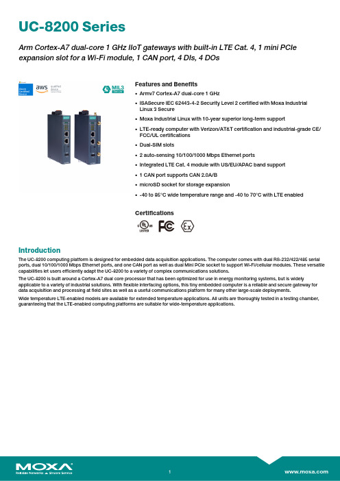
UC-8200SeriesArm Cortex-A7dual-core1GHz IIoT gateways with built-in LTE Cat.4,1mini PCIe expansion slot for a Wi-Fi module,1CAN port,4DIs,4DOsFeatures and Benefits•Armv7Cortex-A7dual-core1GHz•ISASecure IEC62443-4-2Security Level2certified with Moxa IndustrialLinux3Secure•Moxa Industrial Linux with10-year superior long-term support•LTE-ready computer with Verizon/AT&T certification and industrial-grade CE/FCC/UL certifications•Dual-SIM slots•2auto-sensing10/100/1000Mbps Ethernet ports•Integrated LTE Cat.4module with US/EU/APAC band support•1CAN port supports CAN2.0A/B•microSD socket for storage expansion•-40to85°C wide temperature range and-40to70°C with LTE enabledCertificationsIntroductionThe UC-8200computing platform is designed for embedded data acquisition applications.The computer comes with dual RS-232/422/485serial ports,dual10/100/1000Mbps Ethernet ports,and one CAN port as well as dual Mini PCIe socket to support Wi-Fi/cellular modules.These versatile capabilities let users efficiently adapt the UC-8200to a variety of complex communications solutions.The UC-8200is built around a Cortex-A7dual core processor that has been optimized for use in energy monitoring systems,but is widely applicable to a variety of industrial solutions.With flexible interfacing options,this tiny embedded computer is a reliable and secure gateway for data acquisition and processing at field sites as well as a useful communications platform for many other large-scale deployments.Wide temperature LTE-enabled models are available for extended temperature applications.All units are thoroughly tested in a testing chamber, guaranteeing that the LTE-enabled computing platforms are suitable for wide-temperature applications.AppearanceUC-8210UC-8220SpecificationsComputerCPU Armv7Cortex-A7dual-core1GHzDRAM2GB DDR3LSupported OS Moxa Industrial Linux1(Debian9,kernel4.4),2027EOLMoxa Industrial Linux31(Debian11,kernel5.10),2031EOLSee /MILStorage Pre-installed8GB eMMCExpansion Slots MicroSD(SD3.0)socket x13OS is selectable via Moxa Computer Configuration System(CCS)for CTO models.For the model names,see the Ordering Information section of thedatasheet PDF file.Computer InterfaceEthernet Ports Auto-sensing10/100/1000Mbps ports(RJ45connector)x2 Serial Ports RS-232/422/485ports x2,software selectable(DB9male) CAN Ports CAN2.0A/B x1(DB9male)Digital Input DIs x4Digital Output DOs x4USB2.0USB2.0hosts x1,type-A connectorsWi-Fi Antenna Connector UC-8220Models:RP-SMA x2Cellular Antenna Connector UC-8220Models:SMA x2GPS Antenna Connector UC-8220Models:SMA x1Expansion Slots UC-8220-T-LX:mPCIe slot x2UC-8220-T-LX US/EU/AP Models:mPCIe slot x1SIM Format UC-8220Models:NanoNumber of SIMs UC-8220Models:2Buttons Programmable buttonTPM TPM v2.0Ethernet InterfaceMagnetic Isolation Protection 1.5kV(built-in)Security FunctionsHardware-based Security TPM2.0Hardware Root of Trust Secure BootIntrusion Detection Host-based Intrusion DetectionSecurity Tools Security Diagnostic ToolSecurity Event AuditingSecure UpdateDisk Protection LUKS Disk EncryptionRecovery One-step recovery to the last known secure stateDual-system design with automatic failbackReliability Network Keep AliveNetwork Failover and FailbackSerial InterfaceBaudrate300bps to921.6kbpsData Bits7,8Stop Bits1,2Parity None,Even,Odd,Space,MarkFlow Control RTS/CTS,XON/XOFFADDC(automatic data direction control)for RS-485RTS Toggle(RS-232only)Console Port1x4-pin header to DB9console portRS-232TxD,RxD,RTS,CTS,DTR,DSR,DCD,GNDRS-422Tx+,Tx-,Rx+,Rx-,GNDRS-485-2w Data+,Data-,GNDCAN InterfaceNo.of Ports1Connector DB9maleBaudrate10to1000kbpsIndustrial Protocols CAN2.0ACAN2.0BIsolation2kV(built-in)Signals CAN_H,CAN_L,CAN_GND,CAN_SHLD,CAN_V+,GNDDigital InputsConnector Screw-fastened Euroblock terminalDry Contact Off:openOn:short to GNDIsolation3K VDCSensor Type Wet contact(NPN)Dry contactWet Contact(DI to COM)On:10to30VDCOff:0to3VDCDigital OutputsConnector Screw-fastened Euroblock terminalCurrent Rating200mA per channelI/O Type SinkVoltage24VDC nominal,open collector to30VDCCellular InterfaceCellular Standards LTE Cat.4Band Options US Models:LTE Band2(1900MHz)/LTE Band4(1700MHz)/LTE Band5(850MHz)/LTE Band13(700MHz)/LTE Band17(700MHz)UMTS/HSPA850MHz/1900MHzCarrier Approval:Verizon,AT&TEU Models:LTE Band1(2100MHz)/LTE Band3(1800MHz)/LTE Band5(850MHz)/LTE Band7(2600MHz)/LTE Band8(900MHz)/LTE Band20(800MHz)UMTS/HSPA850MHz/900MHz/1900MHz/2100MHzAP Models:LTE Band1(2100MHz)/LTE Band3(1800MHz)/LTE Band5(850MHz)/LTE Band7(2600MHz)/LTE Band8(900MHz)/LTE Band28(700MHz)UMTS/HSPA850MHz/900MHz/1900MHz/2100MHzReceiver Types GPS/GLONASS/GalileoState-of-the-art GNSS solutionAccuracy Position:2.0m@CEP50Acquisition Hot starts:1.1secCold starts:29.94secSensitivity Cold starts:-145dBmTracking:-160dBmTime Pulse0.25Hz to10MHzLED IndicatorsSystem Power x2Programmable x1SIM card indicator x1Wireless Signal Strength Cellular/Wi-Fi x6Power ParametersNo.of Power Inputs Redundant dual inputsInput Voltage12to48VDCPower Consumption10WInput Current0.8A@12VDCReliabilityAlert Tools External RTC(real-time clock)Automatic Reboot Trigger External WDT(watchdog timer)Physical CharacteristicsDimensions UC-8220Models:141.5x120x39mm(5.7x4.72x1.54in)UC-8210Models:141.5x120x27mm(5.7x4.72x1.06in)141.5x120x27mm(5.7x4.72x1.06in)Weight UC-8210Models:560g(1.23lb)UC-8220Models:750g(1.65lb)Housing SECCMetalIP Rating IP30Installation DIN-rail mountingWall mounting(with optional kit)Environmental LimitsOperating Temperature-40to70°C(-40to158°F)Storage Temperature(package included)-40to85°C(-40to185°F)Ambient Relative Humidity5to95%(non-condensing)Shock IEC60068-2-27Vibration2Grms@IEC60068-2-64,random wave,5-500Hz,1hr per axis(without USB devicesattached)Standards and CertificationsEMC EN55032/35EN61000-6-2/-6-4EMI CISPR32,FCC Part15B Class AEMS IEC61000-4-2ESD:Contact:4kV;Air:8kVIEC61000-4-3RS:80MHz to1GHz:10V/mIEC61000-4-4EFT:Power:2kV;Signal:1kVIEC61000-4-6CS:10VIEC61000-4-8PFMFIEC61000-4-5Surge:Power:0.5kV;Signal:1kV Industrial Cybersecurity IEC62443-4-1IEC62443-4-2Hazardous Locations Class I Division2ATEXIECExCarrier Approvals VerizonAT&TSafety UL62368-1EN62368-1Green Product RoHS,CRoHS,WEEEMTBFTime UC-8210-T-LX-S:708,581hrsUC-8220-T-LX:650,836hrsUC-8220-T-LX-US-S/EU-S/AP-S:528,574hrs Standards Telcordia(Bellcore)Standard TR/SRWarrantyWarranty Period5yearsDetails See /warrantyPackage ContentsDevice1x UC-8200Series computerDocumentation1x quick installation guide1x warranty cardInstallation Kit1x DIN-rail kit(preinstalled)1x power jack6x M2.5mounting screws for the cellular module Cable1x console cableDimensions UC-8210UC-8220Ordering Information12UC-8210-T-LX-SDefault:MIL1(-Debian9),2027EOLOrder WithModel UC-8210-T-LX-S(CTO):MIL3(Debian11)Secure/Standard,2031EOLWith MIL3Secure1GHzDual CoreBuilt in––-40to85°CUC-8220-T-LXDefault:MIL1(-Debian9),2027EOLOrder WithModel UC-8220-T-LX(CTO):MIL3(Debian11)Secure/Standard,2031EOLWith MIL3Secure1GHzDual CoreBuilt in Reserved Reserved-40to70°CUC-8220-T-LX-US-SDefault:MIL1(-Debian9),2027EOLOrder WithModel UC-8220-T-LX-US-S(CTO):MIL3(Debian11)Secure/Standard,2031EOLWith MIL3Secure1GHzDual CoreBuilt inUS region LTEmodulepreinstalledReserved-40to70°CUC-8220-T-LX-EU-SDefault:MIL1(-Debian9),2027EOLOrder WithModel UC-8220-T-LX-EU-S(CTO):MIL3(Debian11)Secure/Standard,2031EOLWith MIL3Secure1GHzDual CoreBuilt inEurope regionLTE modulepreinstalledReserved-40to70°CUC-8220-T-LX-AP-SDefault:MIL1(-Debian9),2027EOLOrder WithModel UC-8220-T-LX-AP-S(CTO):MIL3(Debian11)Secure/Standard,2031EOLWith MIL3Secure1GHzDual CoreBuilt inAPAC regionLTE modulepreinstalledReserved-40to70°CUC-8210-T-LX-S(CTO)MIL3(Debian11)Secure orStandard,2031EOLWith MIL3Secure1GHzDual CoreBuilt in––-40to85°CUC-8220-T-LX(CTO)MIL3(Debian11)Secure orStandard,2031EOLWith MIL3Secure1GHzDual Core–Reserved Reserved-40to70°CUC-8220-T-LX-US-S (CTO)MIL3(Debian11)Secure orStandard,2031EOLWith MIL3Secure1GHzDual CoreBuilt inUS region LTEmodulepreinstalledReserved-40to70°C12UC-8220-T-LX-EU-S (CTO)MIL3(Debian11)Secure orStandard,2031EOLWith MIL3Secure1GHzDual CoreBuilt inEurope regionLTE modulepreinstalledReserved-40to70°CUC-8220-T-LX-AP-S (CTO)MIL3(Debian11)Secure orStandard,2031EOLWith MIL3Secure1GHzDual CoreBuilt inAPAC regionLTE modulepreinstalledReserved-40to70°CAccessories(sold separately)Power AdaptersPWR-12150-EU-SA-T Locking barrel plug,12VDC,1.5A,100to240VAC,EU plug,-40to75°C operating temperature PWR-12150-UK-SA-T Locking barrel plug,12VDC,1.5A,100to240VAC,UK plug,-40to75°C operating temperature PWR-12150-USJP-SA-T Locking barrel plug,12VDC1.5A,100to240VAC,US/JP plug,-40to75°C operating temperature PWR-12150-AU-SA-T Locking barrel plug,12VDC,1.5A,100to240VAC,AU plug,-40to75°C operating temperature PWR-12150-CN-SA-T Locking barrel plug,12VDC,1.5A,100to240VAC,CN plug,-40to75°C operating temperature Power WiringCBL-PJTB-10Non-locking barrel plug to bare-wire cableCablesCBL-F9DPF1x4-BK-100Console cable with4-pin connector,1mWi-Fi Wireless ModulesUC-8200-WLAN22-AC Wireless package for UC-8200V2.0or later with Wi-Fi module,2screws,2spacers,1heat sink,1pad AntennasANT-LTEUS-ASM-01GSM/GPRS/EDGE/UMTS/HSPA/LTE,1dBi,omnidirectional rubber-duck antennaANT-LTE-ASM-04BK704to960/1710to2620MHz,LTE omnidirectional stick antenna,4.5dBiANT-LTE-OSM-03-3m BK700-2700MHz,multiband antenna,specifically designed for2G,3G,and4G applications,3m cable ANT-LTE-ASM-05BK704-960/1710-2620MHz,LTE stick antenna,5dBiANT-LTE-OSM-06-3m BK MIMO Multiband antenna with screw-fastened mounting option for700-2700/2400-2500/5150-5850MHzfrequenciesANT-WDB-ARM-02022dBi at2.4GHz or2dBi at5GHz,RP-SMA(male),dual-band,omnidirectional antennaDIN-Rail Mounting KitsUC-8210DIN-rail Mounting Kit DIN-rail mounting kit for UC-8210with4M3screwsUC-8220DIN-rail Mounting Kit DIN-rail mounting kit for UC-8220with4M3screwsWall-Mounting KitsUC-8200Wall-mounting Kit Wall-mounting kit for UC-8200with4M3screws©Moxa Inc.All rights reserved.Updated Jul18,2023.This document and any portion thereof may not be reproduced or used in any manner whatsoever without the express written permission of Moxa Inc.Product specifications subject to change without notice.Visit our website for the most up-to-date product information.。
原装产品型号对照表12月
6320R2 6320D8
20000 8000
377 255
CLP-500D5C/M/Y彩粉 CLP-500D7K黑粉 CLP-500RB硒鼓 CLP-500RT转印单元 CLP-500WB废粉仓 CLP-K300A CLP-C300A CLP-M300A CLP-Y300A CLP-P300C CLP-R300C CLP-W300A CLP-K600A CLP-C600A CLP-M600A CLP-Y600A CLP-T600A
CLP-350N(5/19ppm)
CLP-610ND(20ppm)/CLP-660N/ND(24ppm)
CLX-6200ND/FX/CLX-6210FX(20ppm)/CLX-6240FX(24PPM)
CLP-500/500N
CLP-300/300N
CLX-2160/2160N/3160N/3160FN
4000 10000 1500
1500 1500 1500 1500 1500 1500 4000 5000 5000 5000 5000 2500 2000 2000 2000
470 953 358
968 305 278 278 278 873 736 872 872 872 1,345 534 601 601 601
CLP-C350A/XIL(2k) CLP-M350A/XIL(2k) CLP-Y350A/XIL(2k) CLP-R350A/XIL CLP-W350A/XIL CLP-K660A/XIL(2.5k) CLP-K660B/XIL(5.5k) CLP-C660A/XIL(2k) CLP-C660B/XIL(5k) CLP-M660A/XIL(2k) CLP-M660B/XIL(5k) CLP-Y660A/XIL(2k) CLP-Y660B/XIL(5k) CLP-T660A/XIL(50k) CLP-T660B/XIL(50k)
课程库中英文对照

SPSS统计软件 TCP/IP内核分析及应用 TCP/IP协议分析 TCP/IP协议分析 TCP/IP协议分析 UML技术 UML技术 UNIX操作系统结构 UNIX操作系统结构 UNIX系统与软件开发环境 UNIX系统与软件开发环境 UNIX系统与软件开发环境 UNIX系统与软件开发环境 UNIX系统与软件开发环境 程序设计 VB程序设计 VB程序设计 VB程序设计 VB程序设计 VB程序设计 VB程序设计 VB程序设计 VB程序设计 VB程序设计 VB程序设计 VC++程序设计 VC++程序设计 VC++程序设计 VC++程序设计 VFP程序设计 VLSI系统设计和实践 Web程序设计技术 Web技术与网站规划 Web技术与网站规划 Web开发技术 Web开发技术 Web开发技术 Web开发技术 Web开发技术 Web应用开发技术 Web应用开发技术 Web应用开发技术 Web应用开发技术 Web应用开发实践 Web应用开发实践 Win32汇编语言程序设计 Win32汇编语言程序设计
DSP芯片原理与应用 DSP原理与应用 DSP在运动控制中的应用 EC课程设计 EC课程设计 EDA技术 EDA技术 EDA技术 EDA技术 EDA技术与VHDL语言 EDA技术与VHDL语言 EDA技术与VHDL语言 EDA技术与VHDL语言 EDA技术与VHDL语言 EMC理论与实践 EMC理论与实践 EMC理论与实践 ERP/Web应用开发实践 ERP实践 ERP实践 ERP实践 ERP实施课程设计 ERP实施课程设计 ERP实施课程设计 ERP系统原理与技术 ERP系统原理与应用 ERP系统原理与应用 ERP系统原理与应用 ERP系统原理与应用 ERP系统原理与应用 ERP原理 ERP原理 ERP原理 ESP ESP Fortran程序设计 Fortran程序设计 IBM大机与Cobol语言入门 Internet 程序设计 Internet/Intranet技术与应用 Internet/Intranet技术与应用 Internet/Intranet技术与应用 Internet程序设计 Internet程序设计 Internet功能及应用 Internet技术与应用 Internet技术与应用
cxw-220-et03s产品知识与cxw-220-jd01g产品知识

1规格及附件1:规格12外部装配部件图3 外形尺寸图4 安装方法及注意事项1:安装方法①吸油烟机最低部位与炉灶表面的参考距离为670~750mm,但该距离应至少为650mm。
如果炉灶规定了较大的安装距离,则应以炉灶的规定为准。
②如安装参考图所示,在墙上钻5个深度约为60mm的Φ10孔,最上方2孔埋入2个Φ 10金属膨胀螺栓,其余3孔埋入Φ 10塑料膨胀管,用膨胀螺栓的螺母和2只Φ5木螺钉将主机挂板紧固在墙上(中间一孔暂不拧螺钉)。
③若需安装上装饰罩,请在主机挂板正上方的适当位置,钻2个Φ10孔(如安装参考图所示),分别埋入2只Φ10塑料膨胀管,用Φ5只木螺钉将上装饰罩挂板水平紧固在墙上。
④将主机挂在主机挂板上,并确保主机挂牢和平稳。
⑤如安装参考图所示,将Φ5木螺钉拧入主机挂板的中间孔,以防主机掀翻。
⑥将出风管插入出风口环槽底部,用2只ST4*10自攻螺钉将出风管固定在出风口上,并在衔接处用铝箔胶带固定密封。
⑦将出风管从预先钻好的Φ185墙孔中引出室外,室外的出口应低于室内。
若墙内排烟口径小于出风管时,可采用转接头进行转接,连接方式见右图。
注意:1. 加装转接头后,会降低吸烟排气能力。
2.安装时请将出风管充分拉展开,避免排气不畅和增加噪音,并将出风管多余部分截出。
⑧拉出上装饰罩,用2只M4*8螺钉将其紧固在上装饰罩挂板上。
⑧将油杯水平插入器具底部的油杯挂脚中,并平推到位。
⑩接通器具的电源,试运行机器,确认机器的各功能是否正常。
2:注意事项①.本器具请勿与建筑物的金属部(壁内钢丝等)接触,施工时请注意。
②.请勿将机体埋入墙内,墙壁内的钢丝有漏电场合,会流至机体。
③.使用灶具的宽度应在吸油烟机宽度之内。
④. 吸油烟机排除的气体不应排到用于排出燃烧燃气或其他燃料的烟雾使用的热烟道中。
⑤.请使用随机附件中的出风管,不可采用其他规格的出风管,否则会影响吸烟排气效果。
⑥.出风管不可拉开太长和弯曲太多,以免影响吸烟排气效果。
电脑耗材

台 个 个 套 套 个 套 套 个 个 块 根 个 米
1 3 1 1 1 1 1 1 1 5 2 4 273 419
电脑配件库存状况表
序号 01 010001 010002 02 020001 020002 02000304 04 040001 040002 05 050001 050002 050003 050004 050005 050006 050007 050008 06 060001 07 070001 070002 070003 070004 070005 070006 070007 070008 070009 08 080001 080002 080003 080004 080005 09 090001 090002 10 100001 100002 100003 11 110001 110002 110003 110004 12 120001 名称 电源 SUPERMICRO PWS-865-PQ电源 SUPERMICRO SP650-RP电源 CPU E5410 CPU INTEL i7 950 CPU INTEL i7 970 CPU 硬盘 SATA 硬盘 500G SATA 硬盘 1TB SATA 硬盘 2TB 数帅移动网盘 主板 X58A-UD3R主板 X7DWA-N主板 散热器 S90F 散热风扇 cooler master散热器 黄铜色散热器 Bushless风扇 V12内存散热器 D39267-002散热器 S2N-6FMCS-L7-GP散热器 S2N-PLMH6-07-GP散热器 刻录机 DVR-219CH刻录机 陈列卡 3220阵列卡 3300阵列卡 4320阵列卡 8300阵列卡 8350阵列卡 1204阵列卡 39160SCSI卡 3860QSCSI卡 5K0CT05501ML阵列线 网卡 Lopstar TE-100TXE Rev 1.3网卡 Qxcomm 56K网卡 PC2-X双口网卡 897654双口网卡 0H092P双网卡 显示器 戴尔2211显示器 戴尔2311显示器 软件 雷特字幕 江民杀毒软件 FreeEdit DV LE 2.0编辑软件 鼠标键盘 戴尔键盘 戴尔鼠标 雷特鼠键套装 DELL无线鼠标 鼠标垫 机箱 SC733TQ-665B机箱 数量 个 个 个 个 个 块 块 块 套 块 块 个 个 个 个 个 个 个 个 台 块 块 块 块 块 块 块 块 根 块 块 块 块 块 台 台 套 套 套 个 个 套 个 个 台 1 2 1 4 0 1 36 0 1 4 1 1 3 2 8 2 2 1 7 0 1 3 32 1 4 2 1 1 2 1 1 1 3 1 1 5 23 2 1 3 0 4 1 40 14 备注
三星SIRIUS软启动器3RW5525-1HA14商品说明书
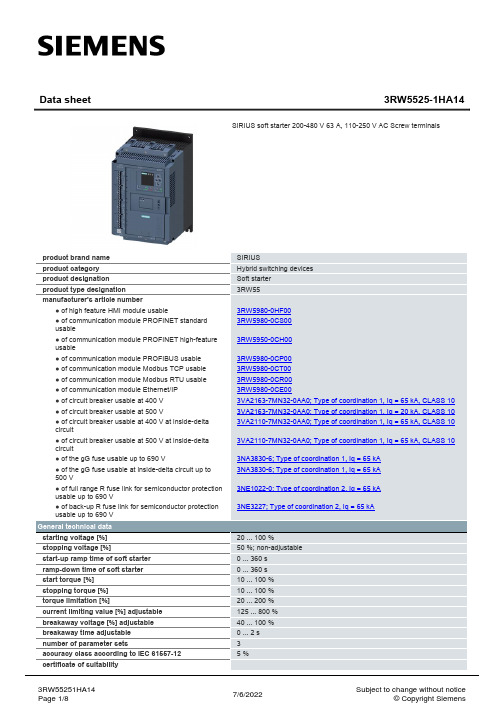
General technical data
starting voltage [%] stopping voltage [%] start-up ramp time of soft starter ramp-down time of soft starter start torque [%] stopping torque [%] torque limitation [%] current limiting value [%] adjustable breakaway voltage [%] adjustable breakaway time adjustable number of parameter sets accuracy class according to IEC 61557-12 certificate of suitability
- 1、下载文档前请自行甄别文档内容的完整性,平台不提供额外的编辑、内容补充、找答案等附加服务。
- 2、"仅部分预览"的文档,不可在线预览部分如存在完整性等问题,可反馈申请退款(可完整预览的文档不适用该条件!)。
- 3、如文档侵犯您的权益,请联系客服反馈,我们会尽快为您处理(人工客服工作时间:9:00-18:30)。
簡單來說,電子商務就是在網際網路上做生意。
凡是透過電腦和Internet 所進行的商業活動(如商品交易、資訊交流、建立商業社群、娛樂等),都是電子商務的範疇。
電子商務分類:
B2B
企業對企業間交易模式主要是指企業間的整合運作,如電子訂單採購或下單、客戶服務、技術支援等,企業合作夥伴之間可以打破地域的限制,更方便及有效率地取得最新資訊而且能省去許多人力資源。
B2C
企業對消費者間交易模式是指企業透過網際網路將商品直接在網路上銷售,或是在網路上提供服務,或做為企業形像推廣的另一個媒體。
包括線上購物、線上訂票、線上資料庫等,是目前電子商務網站中最常見的模式。
C2C
消費者對消費者間交易模式主要是為消費者之間透過網站來達到資訊交流,以進行交易的方式。
如一般的個人式的拍賣網站或BBS站上的二手跳蚤市場等。
電子商務的四流
電子商務建立在網際網路上,並提供方便、即時和迅速訊息反應的優勢,因應公司組織及商人的需求,達到降低成本又能增進商品及服務品質,而成為今日商業的尖端潮流
電子商務的「四流」是指:商流、物流、金流以及資訊流。
行銷學的產品(Product)、通路(Place)、價格(Price)、促銷(Promotion)稱為4P,與電子商務的四流恰好是相對的。
產品與「商流」可相對、通路與「物流」、價格與「金流」、促銷與「資訊流」可相對。
成功的電子商務網站至少需包括完整的「金流、物流和資訊流」,甚至再加上「商流」的處理機制,形成電子商務的四流。
善加運用電子商務的處理技術,賣方可以將訂單輸入網站的資料庫、或查詢倉庫庫存量和客戶的狀態,安排送貨並且完成所有上下游之間的溝通。
縮短
時間與空間的距離,成為公司內部員工與合作夥伴間互動良好的方式,並加強與客戶間的關係,因而增加企業的競爭力。
電子商務兩大支柱
公共政策
是指與電子商務相關連的公共政策納入管理,例如使用權、隱私權和資訊定價等等;有別於一般商業法規所管轄的商業活動,電子商務目前著重於基本政策和法律問題。
技術標準
為了達到整個網路的相容性,而將資訊出版、使用者介面與傳輸的方式等統一。
電子商務相關名詞
電子市集(eMarketplace)是指企業與企業間的電子運作與交易平台。
封閉式電子市集(Private eMarketplace),與SCM供應鏈管理方式很纇式。
電子採購(eProcedurement)是指在電子市集中的買方處理運作部分。
電子配銷(eDistribution)是指電子市集中賣方的貨品配銷處理運作部分。