can_bus
CANBUS原理介绍

CAN总线原理介绍一.现场总线简介1、现场总线的概念:现场总线是应用在生产现场,在微机化测量控制设备之间实现双向串行多节点数字通信的系统。
也被称为开放式的数字化多节点通信的底层控制网络。
现场总线作为智能设备的联系纽带,把挂接在总线上的作为网络节点的智能设备连接为网络系统,并进一步构成自动化系统,实现基本控制、补偿计算、参数修改、报警、显示、监控、优化及控管一体化的综合自动化功能。
2、几种较有影响的现场总线技术:基金会现场总线(FF-Foundation Fieldbus), Lonworks, PROFIBUS, HART, CAN 现场总线是几种较重要的现场总线技术。
二.CAN总线技术:1、CAN总线简介:CAN (Controller Area Network)—控制器局域网。
它是一种有效支持分布式控制或实时控制的串行通信网络。
CAN总线最早是由德国Bosch公司在80年代初为解决现代汽车中众多的控制与测试仪器之间的数据交换而开发的一种串行数据通信协议,它是一种多主总线,通信介质可以是双绞线、同轴电缆、光导纤维,通信速率可达1Mbps。
CAN总线通信接口中集成了CAN协议的物理层,数据链路层功能,可完成对通信数据的成帧处理,包括位填充,数据块编码,循环冗余校验,优先级判别等项工作。
2、CAN总线技术的主要特点:⑴多主站依据优先权进行访问。
CAN为多主方式工作,网络上的任一节点在任何时候都可以主动地向网络上的其他节点发送信息。
⑵采用短帧传送。
CAN采用短帧结构,废除了对传统的站地址编码,而是对通讯数据进行编码。
每帧数据信息为0。
8个字节,具体长度由用户决定。
⑶无破坏基于优先权的仲裁。
当多个节点同时向总线发送信息时,优先级较低的节点会主动的退出总线发送,而最高优先级的节点可不受影响地继续传输数据,从而大大节省了总线冲突时间。
⑷借助接收滤波的多地址帧传送。
CAN只需通过报文滤波即可实现点对点,一点对多点以及全局广播等几种方式来传输数据,无需专门的“调度”。
CANBUS总线说明

CANBUS总线说明CANBUS特性系统采用CANBUS通讯方式,设计为现场总线连接方式,即是手拉手接线方式组网非常方便,终端上并跳接120欧姆电阻,总线方式实现“即插即用”的便利条件。
CAN总线可以由多个子网络组成,每个子网络必须满足以下条件:(1)同一网络中允许挂接110个节点(2)传输距离最远为10千米如果子网络超出以上任一条件,须增加网络桥扩展可组成多重网。
以下是CANBUS单个网络的结构:CAN总线方式优点:1、线路简单有利于综合布线,节省管线材,具有组网自由、安装方便、扩充容易,改造灵活。
2、硬件连接简单, 具有实时性强、可靠性高、通信速率快、结构简单、互操作性好、总线协议具有完善的错误处理机制、灵活性高和价格比高。
3、数据传输速率高,在传输距离小于40 m时,最大传输速率可达1 Mb/s,传输距离10km时速率达5kbps。
4、传输距离远,扰干扰能力强。
5、具有突出的可靠性、实时性和灵活性。
6、采用点对点、一点对多点及全局广播几种数据收发方式。
7、实现单点、双点、多点、区域、群组控制、场景设置、定时开关、亮度手自动调节、红外线探测、集中监控、遥控等多种照明控制控制。
8、可实现全分布式多机系统,并且无主、从机之分,每个节点均主动发送报文,可方便地构成多机备份系统。
9、采用非破坏性总线仲裁技术,两个节点同时上传送数据时,优先级低的节点主动停止数据发送,优先级高的节点可不受影响地继续传输数据,有效避免了总线冲突。
10、短帧结构总线上每帧有效字节数最多为8个,并有可靠的错误检测和处理机制CRC 循环冗余校验措施,受干扰数据出错率极低,万一某一节点出现严重错误,可自动脱离总线,总线上的其他操作不受影响。
11、控制回路与强电分离,采用弱电DC24VCANBUS综合布线CANBUS总线为4线制现场总线采用STP 4*0.75将其所有元件连成一个网络,为了保证系统通讯的可靠,布线时CAN总线尽量不与强电缆共用同一线槽,应将CAN总线单独穿钢管或PVC管敷设,并与电力电缆的水平距离至少大于300mm,下列为某项目布线图:1、CANBUS总线(控制面板)采用STP 4*0.75手拉手方式进行连接汇聚于配电箱。
汽车CAN总线详细教程

◆1992年,CIA(CAN in Automation)用户组织成立,之 后制定了第一个CAN应用层“CAL”。 ◆ 1994年开始有了国际CAN学术年会(ICC)。 ◆ 1994年美国汽车工程师协会以CAN为基础制定了 SAEJ1939标准,用于卡车和巴士控制和通信网络。 ◆ 到今天,几乎每一辆欧洲生产的轿车上都有CAN;高级客 车上有两套CAN,通过网关互联;1999年一年就有近6千万个 CAN控制器投入使用;2000年销售1亿多CAN的芯片;2001 年用在汽车上的CAN节点数目超过1亿个 。 ◆ 但是轿车上基于CAN的控制网络至今仍是各大公司自成系 统,没有一个统一标准。
(6)通信速率最高可达1MB/s(此时距离最长40m)。
(7)节点数实际可达110个。
(8)采用短帧结构,每一帧的有效字节数为8个。
(9)每帧信息都有CRC校验及其他检错措施,数据出错率极低。
(10)通信介质可采用双绞线,同轴电缆和光导纤维,一般采用 廉价的双绞线即可,无特殊要求。
(11) 节点在错误严重的情况下,具有自动关闭总线的功能,切 断它与总线的联系,以使总线上的其他操作不受影响。
带有三个中央控制单元和总线系统的车
带有三个中央控制单元的CAN驱动网络
车用网络发展原因
电子技术发展----线束增加 线控系统(X-BY-WIRE) 计算机网络的广泛应用 智能交通系统的应用
汽车发展带来的问题
(1)汽车电子技术的发展汽车上电子装置越来 越多汽车的整体布置空间缩小
(2)传统电器设备多为点到点通信导致了庞大 的线束
(3)大量的连接器导致可靠性降低。 粗大的线束与汽车中有限的可用空间之间的矛
盾越来越尖锐,电缆的体积、可靠性和重量成为越 来越突出的问题,而且也成为汽车轻量化和进一步 电子化的最大障碍,汽车的制造和安装也变得非常 困难。 (4)存在冗余的传感器。
canbus定义

目 录
1.1 从“罐头”说起
1.2 通信的层次
1.3 什么是现场总线
1.4 CAN总线简介
从“罐头”说起
另一个意思:罐头
CAN
从“罐头”说起„„
童年的“传声筒”
工作原理:
左“罐头”
把声波产生的振动传导到绷紧的绳子上。
绳
子
通过绳子将这种振动传导到另一个罐头上。
把振动传导给空气形成声波。
右“罐头”
童年的“传声筒”
喊话的内容 罐头 绳子 振动波 罐头
电缆 需要传递的数据 电路板
电信号 电路板
两者原理相通
童年的“传声筒”
实现 —— 多方通话
典型的现场总线应用
目 录
1.1 从“罐头”说起
1.2 通信的层次
1.3 什么是现场总线
1.4 CAN总线简介
通信是分层的,这个概念应该贯彻在我们学习任何通信系统的整个过程中。
当 n = 5 时,需要 10 根线 当 n = 10 时,需要 45 根线 当 n = 20 时,需要 190 根线
仅需 ≤ n+1根线
总线:bus。信息在一条公共通道上传
输,信息接收者从通道上接收所有信息, 并根据规则过滤发送给自己的信息。
连线多,线路复杂
连线少,结构清晰
什么是现场总线
现场总线:Fieldbus,应用于工业现场,采用总线方式连接多个设备,用于传输
主流的现场总线
根据应用领域不同,世界上存在很多种现场总线,以下为一些主流的现场总线:
名称 推广组织/厂商 BOSCH CI PNO WorldFIP InterbusClub FF ISO Echelon HART MITSUBSHI 说明 常用的现场总线,由CiA、ODVA、SAE等协会管理与推广 AB、Rockwell制定的现场总线,应用于工业控制领域 德国SIEMENS制定,欧洲现场总线标准三大总线之一 法国制定,欧洲现场总线标准三大总线之一 德国PHOENIX制定,应用于工业控制 基金会现场总线控制系统,适用于石油化工领域 国际标准列车通信网TCN,包括MVB与WTB两类 美国Echelon制定与维护,应用于建筑自动化、列车通信 早期的一种现场总线标准,适用于智能测控仪表 工业PLC与运动控制领域的现场总线
canbus标准
CAN总线(CAN-bus)是一种串行通信总线系统,被广泛应用于汽车和工业自动化领域,CAN总线的物理层定义了总线的位速率、位定时、电气特性、传输介质等。
CAN总线的位速率可以根据实际需要进行设置,常见的有500Kbps和250Kbps等。
CAN总线的位定时决定了通信的可靠性和稳定性,需要满足一定的时序要求。
数据链路层是CAN总线的重要组成部分,包括逻辑链路控制、媒体访问控制和差错控制等子层。
逻辑链路控制子层负责建立和维护通信节点之间的逻辑连接;媒体访问控制子层采用CSMA/CD协议,实现总线访问控制和数据传输;差错控制子层用于检测和处理总线上的错误。
在实际应用中,CAN总线可以采用单线或双线模式,根据实际情况选择合适的线数和线型。
同时,为了提高总线的可靠性和稳定性,可以采用一些措施,如波特率自适应、节点故障检测和自动重发等。
总之,CAN总线是一种广泛应用于汽车和工业自动化领域的串行通信总线系统,具有高可靠性和稳定性。
CAN总线标准定义了总线的物理层和数据链路层,为实际应用提供了重要的支持和保障。
大众CANBUS

新型诊断线能够适用于旧型诊断接口。
针脚号 1 4 5 6 7
14 15 16
对应的线束 15号线 接地 接地 CANBUS(高) k线 CANBUS(低) L线 30号线
注:未标明的针脚号暂未使用。
功能
1. Canbus上的信息
由于不同区域Canbus总线的速率和识别代号不同,因此一个信号要从一个总 线进入到另一个总线区域,必须把它的识别信号和速率进行改变,能够让另 一个系统接受,这个任务由网关(Gateway)来完成。另外,网关还具有改变信 息优先级的功能。如车辆发生相撞事故,气囊控制单元会发出负加速度传感 器的信号,这个信号的优先级在驱动系统是非常高,但转到舒适系统后,网 关调低了它的优先级,因为它在舒适系统功能只是打开门和灯。
大众汽车基本培训
基本技术
CAN 数据总线(CAN-BUS)
售后服务培训中心
12.2002
基本内容: 简介
基本构造 数据传输 功能 驱动系统 舒适系统 传送安全性和故障处理
简介
Canbus的由来
由于现代汽车的技术水平大幅提高,要求能对更多的汽车运行参数进行控制,因而汽车 控制器的数量在不断的上升,从开始的几个发展到几十个以至于上百个控制单元。控制 单元数量的增加,使得它们互相之间的信息交换也越来越密集。为此德国BOSCH公司开 发了一种设计先进的解决方案-CAN数据总线,提供一种特殊的局域网来为汽车的控制 器之间进行数据交换。
域网。其速率分别为(Kbi0;
舒适系统(由30号线激活):100
信息系统(由30号线激活):100;
诊断系统(由30号线激活): 500
仪表系统(由15号线激活): 100;
CAN BUS
在信息数据列中有11位的状态区,这11位二进制中 前7位既是发送信息的控制器标识符,同时又表示 了它的优先级,即从前往后数,前面零越多,优先 级越高。而后4位则是这个控制器发送不同信息的 编号,如发动机控制单元既要发送转速信号,又要 发送水温等信号,则后4位就有所不同。
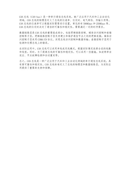
CAN-BUS系统
Canbus系统的难题-发送和接受的同步
广播原理:一家发送,大家接 收
CAN-BUS系统
CAN-BUS系统组成:
CAN收发器: 安装在控制器内部,同时兼具接受和发送的功能,将控制器传来的数据化为 电 信号并将其送入数据传输线。 数据传输终端:是一个电阻,防止数据在线端被反射,以回声的形式返回,影响数据的传 输。 数据传输线:双向数据线,由高低双绞线组成。
针脚号 1 4 5 6 7 14 15 16 对应的线束 15号线 接地 接地 CANBUS(高) k线 CANBUS(低) L线 30号线
注:未标明的针脚号暂未使用。
CAN-BUS系统
Canbus上的信息 Canbus上的信息是以二进制形式出现的 。也就是说控制单元将信息转换成二进制 ,Canbus用电平来模拟二进制,接受控 制单元将电平转换成二进制数据,再将二 进制数据转换成正常数据。
CAN-BUS系统
CAN 诊断
CAN 信息
CAN 驱动 CAN 舒适 CAN 仪表
CAN-BUS系统
CAN-区域图
诊断接口 网关
发动机
变速箱
ABS J104
ESP传 感器
J533
雨括器 L
安全气囊 J234
G85
电动转向 J500 转向柱 J527
收音机
车载电话
雨括器 R
J519
CANBUS介绍
CANBUS介绍作为ISO11898CAN标准的CANBus(ControLLer Area Net-work Bus),是制造厂中连接现场设备(传感器、执行器、控制器等)、面向广播的串行总线系统,最初由美国通用汽车公司(GM)开发用于汽车工业,后日渐增多地出现在制造自动化行业中。
1、CANBus系统组成及性能CANBus系统通过相应的CAN接口连接工业设备(如限位开关、光电传感器、管道阀门、电机启动器、过程传感器、变频器、显示板、PLC和PCI 作站等)构成低成本网络。
直接连接不仅提供了设备级故障诊断方法,而且提高了通信效率和设备的互换性。
CANBus数据传输速率为1Mbit/s,线路距离lkm,基本站点数64,传输媒体是屏蔽双绞线或光纤。
2、CANBus数据链路控制特点CANBus数据链路层协议采用平等式(Peer to peer)通信方式,即使主机出现故障,系统其余部分仍可运行(当然性能受一定影响)。
当一个站点状态改变时,它可广播发送信息到所有站点。
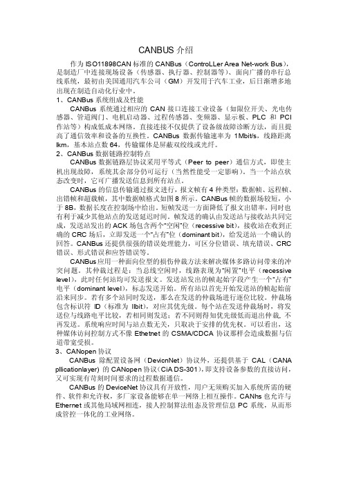
CANBus的信息传输通过报文进行,报文帧有4种类型:数据帧、远程帧、出错帧和超载帧,其中数据帧格式如图8所示。
CANBus帧的数据场较短,小于8B,数据长度在控制场中给出。
短帧发送一方面降低了报文出错率,同时也有利于减少其他站点的发送延迟时间。
帧发送的确认由发送站与接收站共同完成,发送站发出的ACK场包含两个“空闲”位(recessive bit),接收站在收到正确的CRC场后,立即发送一个“占有”位(dominant bit),给发送站一个确认的回答。
CANBus还提供很强的错误处理能力,可区分位错误、填充错误、CRC 错误、形式错误和应答错误等。
CANBus应用一种面向位型的损伤仲裁方法来解决媒体多路访问带来的冲突问题。
其仲裁过程是:当总线空闲时,线路表现为“闲置”电平(recessive level),此时任何站均可发送报文。
发送站发出的帧起始字段产生一个“占有”电平(dominant level),标志发送开始。
- 1、下载文档前请自行甄别文档内容的完整性,平台不提供额外的编辑、内容补充、找答案等附加服务。
- 2、"仅部分预览"的文档,不可在线预览部分如存在完整性等问题,可反馈申请退款(可完整预览的文档不适用该条件!)。
- 3、如文档侵犯您的权益,请联系客服反馈,我们会尽快为您处理(人工客服工作时间:9:00-18:30)。
BOSCHCAN SpecificationVersion 2.01991, Robert Bosch GmbH, Postfach 50, D-7000 Stuttgart 1The document as a whole may be copied and distributed without restrictions. However, the usage of it in parts or as a whole in other documents needs the consent of Robert Bosch GmbH. Robert Bosch GmbH retains the right to make changes to this document without notice and does not accept any liability for errors.Imported into Framemaker 4 by:Chuck Powers, Motorola MCTG Multiplex Applications, April 5,1995.BOSCH Sep. 1991CAN Specification 2.0page 1RecitalThe acceptance and introduction of serial communication to more and more applications has led to requirements that the assignment of message identifiers to communication functions be standardized for certain applications. These applications can be realized with CAN more comfortably, if the address range that originally has been defined by 11 identifier bits is enlargedTherefore a second message format (’extended format’) is introduced that provides a larger address range defined by 29 bits. This will relieve the system designer from compromises with respect to defining well-structured naming schemes. Users of CAN who do not need the identifier range offered by the extended format, can rely on the conventional 11 bit identifier range (’standard format’) further on. In this case they can make use of the CAN implementations that are already available on the market, or of new controllers that implement both formats.In order to distinguish standard and extended format the first reserved bit of the CAN message format, as it is defined in CAN Specification 1.2, is used. This is done in such a way that the message format in CAN Specification 1.2 is equivalent to the standard format and therefore is still valid. Furthermore, the extended format has been defined so that messages in standard format and extended format can coexist within the same network.This CAN Specification consists of two parts, with•Part A describing the CAN message format as it is defined in CAN Specification 1.2;•Part B describing both standard and extended message formats.In order to be compatible with this CAN Specification 2.0 it is required that a CAN implementation be compatible with either Part A or Part B.NoteCAN implementations that are designed according to part A of this or according to previous CAN Specifications, and CAN implementations that are designed according to part B of this specification can communicate with each other as long as it is not made use of the extended format.PART ABOSCH Sep. 1991ContentsPart A - page 3 1INTRODUCTION (4)2BASIC CONCEPTS (5)3MESSAGE TRANSFER (10)3.1Frame Types (10)3.1.1DATA FRAME (10)3.1.2REMOTE FRAME (15)3.1.3ERROR FRAME (16)3.1.4OVERLOAD FRAME (17)3.1.5INTERFRAME SPACING (18)3.2Definition of TRANSMITTER/RECEIVER (20)4MESSAGE VALIDATION (21)5CODING (22)6ERROR HANDLING (23)6.1Error Detection (23)6.2Error Signalling (23)7FAULT CONFINEMENT (24)8BIT TIMING REQUIREMENTS (27)9INCREASING CAN OSCILLATOR TOLERANCE (31)9.1Protocol Modifications (31)BOSCHSep. 1991Part A - page 41 INTRODUCTIONThe Controller Area Network (CAN) is a serial communications protocol which efficiently supports distributed realtime control with a very high level of security.Its domain of application ranges from high speed networks to low cost multiplex wiring.In automotive electronics, engine control units, sensors, anti-skid-systems, etc. are connected using CAN with bitrates up to 1 Mbit/s. At the same time it is cost effective to build into vehicle body electronics, e.g. lamp clusters, electric windows etc. to replace the wiring harness otherwise required.The intention of this specification is to achieve compatibility between any two CAN implementations. Compatibility, however, has different aspects regarding e.g. electrical features and the interpretation of data to be transferred. To achieve design transparency and implementation flexibility CAN has been subdivided into different layers.•the (CAN-) object layer •the (CAN-) transfer layer •the physical layer The object layer and the transfer layer comprise all services and functions of the data link layer defined by the ISO/OSI model. The scope of the object layer includes •finding which messages are to be transmitted •deciding which messages received by the transfer layer are actually to be used,•providing an interface to the application layer related hardware.There is much freedom in defining object handling. The scope of the transfer layer mainly is the transfer protocol, i.e. controlling the framing, performing arbitration, error checking, error signalling and fault confinement. Within the transfer layer it is decided whether the bus is free for starting a new transmission or whether a reception is just starting. Also some general features of the bit timing are regarded as part of the transfer layer. It is in the nature of the transfer layer that there is no freedom for modifications.The scope of the physical layer is the actual transfer of the bits between the different nodes with respect to all electrical properties. Within one network the physical layer, of course, has to be the same for all nodes. There may be, however, much freedom in selecting a physical layer.The scope of this specification is to define the transfer layer and the consequences of the CAN protocol on the surrounding layers.Introduction Edited by Foxit Reader Copyright(C) by Foxit Software Company,2005-2008For Evaluation Only.BOSCHSep. 1991Part A - page 52 BASIC CONCEPTSCAN has the following properties•prioritization of messages •guarantee of latency times •configuration flexibility •multicast reception with time synchronization •system wide data consistency •multimaster •error detection and signalling •automatic retransmission of corrupted messages as soon as the bus is idle again •distinction between temporary errors and permanent failures of nodes and autonomous switching off of defect nodes Layered Structure of a CAN NodeObject Layer- Message Filtering- Message and Status HandlingTransfer Layer- Fault Confinement- Error Detection and Signalling- Message Validation- Acknowledgment- Arbitration- Message Framing- Transfer Rate and TimingPhysical Layer- Signal Level and Bit Representation- Transmission MediumApplication LayerBasic Concepts Edited by Foxit Reader Copyright(C) by Foxit Software Company,2005-2008For Evaluation Only.BOSCHSep. 1991Part A - page 6 •The Physical Layer defines how signals are actually transmitted. Within thisspecification the physical layer is not defined so as to allow transmission medium and signal level implementations to be optimized for their application.•The Transfer Layer represents the kernel of the CAN protocol. It presentsmessages received to the object layer and accepts messages to be transmitted from the object layer. The transfer layer is responsible for bit timing andsynchronization, message framing, arbitration, acknowledgment, error detection and signalling, and fault confinement.•The Object Layer is concerned with message filtering as well as status andmessage handling.The scope of this specification is to define the transfer layer and the consequences of the CAN protocol on the surrounding layers.MessagesInformation on the bus is sent in fixed format messages of different but limited length (see section 3: Message Transfer). When the bus is free any connected unit may start to transmit a new message.Information RoutingIn CAN systems a CAN node does not make use of any information about the system configuration (e.g. station addresses). This has several important consequences.System Flexibility: Nodes can be added to the CAN network without requiring any change in the software or hardware of any node and application layer.Message Routing: The content of a message is named by an IDENTIFIER. The IDENTIFIER does not indicate the destination of the message, but describes the meaning of the data, so that all nodes in the network are able to decide by MESSAGE FILTERING whether the data is to be acted upon by them or not.Multicast: As a consequence of the concept of MESSAGE FILTERING any number of nodes can receive and simultaneously act upon the same message.Data Consistency: Within a CAN network it is guaranteed that a message is simultaneously accepted either by all nodes or by no node. Thus data consistency of a system is achieved by the concepts of multicast and by error handling.Basic Concepts Edited by Foxit Reader Copyright(C) by Foxit Software Company,2005-2008For Evaluation Only.BOSCH Sep. 1991Part A - page 7Bit rateThe speed of CAN may be different in different systems. However, in a given system the bitrate is uniform and fixed.PrioritiesThe IDENTIFIER defines a static message priority during bus access.Remote Data RequestBy sending a REMOTE FRAME a node requiring data may request another node to send the corresponding DATA FRAME. The DATA FRAME and the corresponding REMOTE FRAME are named by the same IDENTIFIER.MultimasterWhen the bus is free any unit may start to transmit a message. The unit with the message of higher priority to be transmitted gains bus access.ArbitrationWhenever the bus is free, any unit may start to transmit a message. If 2 or more units start transmitting messages at the same time, the bus access conflict is resolved by bitwise arbitration using the IDENTIFIER. The mechanism of arbitration guarantees that neither information nor time is lost. If a DATA FRAME and a REMOTE FRAME with the same IDENTIFIER are initiated at the same time, the DATA FRAME prevails over the REMOTE FRAME. During arbitration every transmitter compares the level of the bit transmitted with the level that is monitored on the bus. If these levels are equal the unit may continue to send. When a ’recessive’ level is sent and a ’dominant’ level is monitored (see Bus Values), the unit has lost arbitration and must withdraw without sending one more bit.SafetyIn order to achieve the utmost safety of data transfer, powerful measures for error detection, signalling and self-checking are implemented in every CAN node.Error DetectionFor detecting errors the following measures have been taken:- Monitoring (transmitters compare the bit levels to be transmitted with the bit levels detected on the bus)- Cyclic Redundancy Check- Bit Stuffing- Message Frame CheckBasic Concepts Edited by Foxit Reader Copyright(C) by Foxit Software Company,2005-2008For Evaluation Only.BOSCH Sep. 1991Basic ConceptsPart A - page 8Performance of Error DetectionThe error detection mechanisms have the following properties:- all global errors are detected.- all local errors at transmitters are detected.- up to 5 randomly distributed errors in a message are detected.- burst errors of length less than 15 in a message are detected.- errors of any odd number in a message are detected.Total residual error probability for undetected corrupted messages: less thanmessage error rate * 4.7 * 10-11.Error Signalling and Recovery TimeCorrupted messages are flagged by any node detecting an error. Such messages are aborted and will be retransmitted automatically. The recovery time from detecting an error until the start of the next message is at most 29 bit times, if there is no further error.Fault ConfinementCAN nodes are able to distinguish short disturbances from permanent failures. Defective nodes are switched off.ConnectionsThe CAN serial communication link is a bus to which a number of units may be connected. This number has no theoretical limit. Practically the total number of units will be limited by delay times and/or electrical loads on the bus line.Single ChannelThe bus consists of a single channel that carries bits. From this data resynchronization information can be derived. The way in which this channel is implemented is not fixed in this specification. E.g. single wire (plus ground), two differential wires, optical fibres, etc.Bus valuesThe bus can have one of two complementary logical values: ’dominant’ or ’recessive’. During simultaneous transmission of ’dominant’ and ’recessive’ bits, the resulting bus value will be ’dominant’. For example, in case of a wired-AND implementation of the bus, the ’dominant’ level would be represented by a logical ’0’ and the ’recessive’ level by a logical ’1’. Physical states (e.g. electrical voltage, light) that represent the logical levels are not given in this specification.BOSCH Sep. 1991Basic ConceptsPart A - page 9AcknowledgmentAll receivers check the consistency of the message being received and will acknowledge a consistent message and flag an inconsistent message.Sleep Mode / Wake-upTo reduce the system’s power consumption, a CAN-device may be set into sleep mode without any internal activity and with disconnected bus drivers. The sleep mode is finished with a wake-up by any bus activity or by internal conditions of the system. On wake-up, the internal activity is restarted, although the transfer layer will be waiting for the system’s oscillator to stabilize and it will then wait until it has synchronized itself to the bus activity (by checking for eleven consecutive ’recessive’ bits), before the bus drivers are set to "on-bus" again.In order to wake up other nodes of the system, which are in sleep-mode, a special wake-up message with the dedicated, lowest possible IDENTIFIER (rrr rrrd rrrr; r =’recessive’ d = ’dominant’) may be used.BOSCH Sep. 1991Part A - page 10 3 MESSAGE TRANSFER3.1 Frame TypesMessage transfer is manifested and controlled by four different frame types:A DATA FRAME carries data from a transmitter to the receivers.A REMOTE FRAME is transmitted by a bus unit to request the transmission of the DATA FRAME with the same IDENTIFIER.An ERROR FRAME is transmitted by any unit on detecting a bus error.An OVERLOAD FRAME is used to provide for an extra delay between the preceding and the succeeding DATA or REMOTE FRAMEs.DATA FRAMEs and REMOTE FRAMEs are separated from preceding frames by an INTERFRAME SPACE.3.1.1 DATA FRAMEA DATA FRAME is composed of seven different bit fields:START OF FRAME, ARBITRATION FIELD, CONTROL FIELD, DATA FIELD, CRC FIELD, ACK FIELD, END OF FRAME. The DATA FIELD can be of length zero.Interframe Space InterframeSpaceStart of FrameArbitration FieldControl FieldData FieldCRC FieldACK FieldEnd of Frameor Overload FrameDATA FRAME Message TransferBOSCHSep. 1991Part A - page 11START OF FRAMEmarks the beginning of DATA FRAMES and REMOTE FRAMEs. It consists of a single ’dominant’ bit.A station is only allowed to start transmission when the bus is idle (see BUS IDLE). All stations have to synchronize to the leading edge caused by START OF FRAME (see ’HARD SYNCHRONIZATION’) of the station starting transmission first.ARBITRATION FIELDThe ARBITRATION FIELD consists of the IDENTIFIER and the RTR-BIT.IDENTIFIERThe IDENTIFIER’s length is 11 bits. These bits are transmitted in the order from ID-10to ID-0. The least significant bit is ID-0. The 7 most significant bits (ID-10 - ID-4) must not be all ’recessive’.RTR BITRemote Transmission Request BITIn DATA FRAMEs the RTR BIT has to be ’dominant’. Within a REMOTE FRAME the RTR BIT has to be ’recessive’.CONTROL FIELDThe CONTROL FIELD consists of six bits. It includes the DATA LENGTH CODE and two bits reserved for future expansion. The reserved bits have to be sent ’dominant’.Receivers accept ’dominant’ and ’recessive’ bits in all combinations.DATA LENGTH CODEThe number of bytes in the DATA FIELD is indicated by the DATA LENGTH CODE.This DATA LENGTH CODE is 4 bits wide and is transmitted within the CONTROL FIELD.Interframe SpaceStart of FrameIdentifierRTR BitControl FieldARBITRATION FIELDData FrameBOSCHSep. 1991Part A - page 12Coding of the number of data bytes by the DATA LENGTH CODE abbreviations:d ’dominant’r ’recessive’DATA FRAME: admissible numbers of data bytes: {0,1,....,7,8}.Other values may not be used.r1r0DLC3DLC2DLC1DLC0or CRC FieldArbitration FieldData Field CONTROL FIELDData Length Codereserved bits012345678d d d d d d d d rd d d d r r r r dd d r r d d r r dd r d r d r d r dDLC3DLC2DLC1DLC0Number of DataBytesData Length CodeData FrameBOSCHSep. 1991Part A - page 13DATA FIELDThe DATA FIELD consists of the data to be transferred within a DATA FRAME. It can contain from 0 to 8 bytes, which each contain 8 bits which are transferred MSB first.CRC FIELDcontains the CRC SEQUENCE followed by a CRC DELIMITER.CRC SEQUENCEThe frame check sequence is derived from a cyclic redundancy code best suited for frames with bit counts less than 127 bits (BCH Code).In order to carry out the CRC calculation the polynomial to be divided is defined as the polynomial, the coefficients of which are given by the destuffed bit stream consisting of START OF FRAME, ARBITRATION FIELD, CONTROL FIELD, DATA FIELD (if present) and, for the 15 lowest coefficients, by 0. This polynomial is divided (the coefficients are calculated modulo-2) by the generator-polynomial:X 15 + X 14 + X 10 + X 8 + X 7 + X 4 + X 3 + 1.The remainder of this polynomial division is the CRC SEQUENCE transmitted over the bus. In order to implement this function, a 15 bit shift register CRC_RG(14:0) can be used. If NXTBIT denotes the next bit of the bit stream, given by the destuffed bit sequence from START OF FRAME until the end of the DATA FIELD, the CRC SEQUENCE is calculated as follows:CRC_RG = 0;// initialize shift register REPEATCRCNXT = NXTBIT EXOR CRC_RG(14);CRC_RG(14:1) = CRC_RG(13:0);// shift left by CRC_RG(0) = 0;// 1 positionData or Control FieldCRC SequenceCRC DelimiterAck FieldCRC FIELDData FrameBOSCHSep. 1991Part A - page 14IF CRCNXT THENCRC_RG(14:0) = CRC_RG(14:0) EXOR (4599hex);ENDIFUNTIL (CRC SEQUENCE starts or there is an ERROR condition)After the transmission / reception of the last bit of the DATA FIELD, CRC_RG contains the CRC sequence.CRC DELIMITERThe CRC SEQUENCE is followed by the CRC DELIMITER which consists of a single ’recessive’ bit.ACK FIELDThe ACK FIELD is two bits long and contains the ACK SLOT and the ACK DELIMITER.In the ACK FIELD the transmitting station sends two ’recessive’ bits.A RECEIVER which has received a valid message correctly, reports this to the TRANSMITTER by sending a ’dominant’ bit during the ACK SLOT (it sends ’ACK’).ACK SLOTAll stations having received the matching CRC SEQUENCE report this within the ACK SLOT by superscribing the ’recessive’ bit of the TRANSMITTER by a ’dominant’ bit.ACK DELIMITERThe ACK DELIMITER is the second bit of the ACK FIELD and has to be a ’recessive’bit. As a consequence, the ACK SLOT is surrounded by two ’recessive’ bits (CRC DELIMITER, ACK DELIMITER).END OF FRAMEEach DATA FRAME and REMOTE FRAME is delimited by a flag sequence consisting of seven ’recessive’ bits.CRC FieldACK SlotACK DelimiterEnd of FrameACK FIELDData FrameEdited by Foxit ReaderCopyright(C) by Foxit Software Company,2005-2008For Evaluation Only.BOSCHSep. 1991Part A - page 153.1.2 REMOTE FRAMEA station acting as a RECEIVER for certain data can initiate the transmission of the respective data by its source node by sending a REMOTE FRAME.A REMOTE FRAME is composed of six different bit fields:START OF FRAME, ARBITRATION FIELD, CONTROL FIELD, CRC FIELD, ACK FIELD, END OF FRAME.Contrary to DATA FRAMEs, the RTR bit of REMOTE FRAMEs is ’recessive’. There is no DATA FIELD, independent of the values of the DATA LENGTH CODE which may be signed any value within the admissible range 0...8. The value is the DATA LENGTH CODE of the corresponding DATA FRAME.The polarity of the RTR bit indicates whether a transmitted frame is a DATA FRAME (RTR bit ’dominant’) or a REMOTE FRAME (RTR bit ’recessive’).Inter SpaceInter Space Start of FrameArbitration FieldControl FieldCRC FieldACK FieldEnd of Frameor Overload FrameREMOTE FRAMEFrame FrameRemote FrameBOSCHSep. 1991Part A - page 163.1.3 ERROR FRAMEThe ERROR FRAME consists of two different fields. The first field is given by the superposition of ERROR FLAGs contributed from different stations. The following second field is the ERROR DELIMITER.In order to terminate an ERROR FRAME correctly, an ’error passive’ node may need the bus to be ’bus idle’ for at least 3 bit times (if there is a local error at an ’error passive’ receiver). Therefore the bus should not be loaded to 100%.ERROR FLAGThere are 2 forms of an ERROR FLAG: an ACTIVE ERROR FLAG and a PASSIVE ERROR FLAG.1.The ACTIVE ERROR FLAG consists of six consecutive ’dominant’ bits.2.The PASSIVE ERROR FLAG consists of six consecutive ’recessive’ bits unless it is overwritten by ’dominant’ bits from other nodes.An ’error active’ station detecting an error condition signals this by transmission of an ACTIVE ERROR FLAG. The ERROR FLAG’s form violates the law of bit stuffing (see CODING) applied to all fields from START OF FRAME to CRC DELIMITER or destroys the fixed form ACK FIELD or END OF FRAME field. As a consequence, all other stations detect an error condition and on their part start transmission of an ERROR FLAG. So the sequence of ’dominant’ bits which actually can be monitored on the bus results from a superposition of different ERROR FLAGs transmitted by individual stations. The total length of this sequence varies between a minimum of six and a maximum of twelve bits.An ’error passive’ station detecting an error condition tries to signal this by transmission of a PASSIVE ERROR FLAG. The ’error passive’ station waits for six consecutive bitsDataFrameError FlagError DelimiterInterframe Space or ERROR FRAMEOverload Framesuperposition of Error FlagsError FrameEdited by Foxit ReaderCopyright(C) by Foxit Software Company,2005-2008For Evaluation Only.BOSCHSep. 1991Part A - page 17of equal polarity, beginning at the start of the PASSIVE ERROR FLAG. The PASSIVEERROR FLAG is complete when these 6 equal bits have been detected.ERROR DELIMITERThe ERROR DELIMITER consists of eight ’recessive’ bits.After transmission of an ERROR FLAG each station sends ’recessive’ bits and monitors the bus until it detects a ’recessive’ bit. Afterwards it starts transmitting seven more ’recessive’ bits. 3.1.4 OVERLOAD FRAMEThe OVERLOAD FRAME contains the two bit fields OVERLOAD FLAG and OVERLOAD DELIMITER.There are two kinds of OVERLOAD conditions, which both lead to the transmission of an OVERLOAD FLAG:1.The internal conditions of a receiver, which requires a delay of the next DATA FRAME or REMOTE FRAME.2.Detection of a ’dominant’ bit during INTERMISSION.The start of an OVERLOAD FRAME due to OVERLOAD condition 1 is only allowed to be started at the first bit time of an expected INTERMISSION, whereas OVERLOAD FRAMEs due to OVERLOAD condition 2 start one bit after detecting the ’dominant’ bit.At most two OVERLOAD FRAMEs may be generated to delay the next DATA or REMOTE FRAME.End of Frame or Overload Overload DelimiterInter Space or OVERLOAD FRAMEOverload Framesuperposition of Overload FlagsFlagFrame Error Delimiter or Overload DelimiterOverload FrameEdited by Foxit ReaderCopyright(C) by Foxit Software Company,2005-2008For Evaluation Only.BOSCHSep. 1991Part A - page 18OVERLOAD FLAGconsists of six ’dominant’ bits. The overall form corresponds to that of the ACTIVE ERROR FLAG.The OVERLOAD FLAG’s form destroys the fixed form of the INTERMISSION field. As a consequence, all other stations also detect an OVERLOAD condition and on their part start transmission of an OVERLOAD FLAG. (In case that there is a ’dominant’ bit detected during the 3rd bit of INTERMISSION locally at some node, the other nodes will not interpret the OVERLOAD FLAG correctly, but interpret the first of these six ’dominant’ bits as START OF FRAME. The sixth ’dominant’ bit violates the rule of bit stuffing causing an error condition).OVERLOAD DELIMITERconsists of eight ’recessive’ bits.The OVERLOAD DELIMITER is of the same form as the ERROR DELIMITER. After transmission of an OVERLOAD FLAG the station monitors the bus until it detects a transition from a ’dominant’ to a ’recessive’ bit. At this point of time every bus station has finished sending its OVERLOAD FLAG and all stations start transmission of seven more ’recessive’ bits in coincidence. 3.1.5 INTERFRAME SPACINGDATA FRAMEs and REMOTE FRAMEs are separated from preceding frames whatever type they are (DATA FRAME, REMOTE FRAME, ERROR FRAME,OVERLOAD FRAME) by a bit field called INTERFRAME SPACE. In contrast,OVERLOAD FRAMEs and ERROR FRAMEs are not preceded by an INTERFRAME SPACE and multiple OVERLOAD FRAMEs are not separated by an INTERFRAME SPACE.INTERFRAME SPACEcontains the bit fields INTERMISSION and BUS IDLE and, for ’error passive’ stations,which have been TRANSMITTER of the previous message, SUSPEND TRANSMISSION.Overload FrameEdited by Foxit ReaderCopyright(C) by Foxit Software Company,2005-2008For Evaluation Only.BOSCH Sep. 1991Part A - page 19For stations which are not ’error passive’ or have been RECEIVER of the previous message:For ’error passive’ stations which have been TRANSMITTER of the previous message:INTERMISSIONconsists of three ’recessive’ bits.During INTERMISSION no station is allowed to start transmission of a DATA FRAME or REMOTE FRAME. The only action to be taken is signalling an OVERLOAD condition.BUS IDLEThe period of BUS IDLE may be of arbitrary length. The bus is recognized to be free and any station having something to transmit can access the bus. A message, which is pending for transmission during the transmission of another message, is started in the first bit following INTERMISSION.The detection of a ’dominant’ bit on the bus is interpreted as a START OF FRAME.SUSPEND TRANSMISSIONAfter an ’error passive’ station has transmitted a message, it sends eight ’recessive’bits following INTERMISSION, before starting to transmit a further message or recognizing the bus to be idle. If meanwhile a transmission (caused by another station)starts, the station will become receiver of this message.Frame Bus IdleINTERFRAME SPACE Intermission FrameFrame Bus IdleINTERFRAME SPACE Intermission FrameSuspend TransmissionInterframe SpaceBOSCH Sep. 1991Transmitter / ReceiverPart A - page 20 3.2 Definition of TRANSMITTER / RECEIVERTRANSMITTERA unit originating a message is called “TRANSMITTER” of that message. The unit stays TRANSMITTER until the bus is idle or the unit loses ARBITRATION.RECEIVERA unit is called “RECEIVER” of a message, if it is not TRANSMITTER of that message and the bus is not idle.4 MESSAGE VALIDATIONThe point of time at which a message is taken to be valid, is different for the transmitter and the receivers of the message.Transmitter:The message is valid for the transmitter, if there is no error until the end of END OF FRAME. If a message is corrupted, retransmission will follow automatically and according to prioritization. In order to be able to compete for bus access with other messages, retransmission has to start as soon as the bus is idle.Receivers:The message is valid for the receivers, if there is no error until the last but one bit of END OF FRAME.。