NEC协议的红外遥控器驱动程序修订稿
常用红外遥控协议

常用红外遥控协议一、NEC协议NEC ProtocolTo my knowledge the protocol I describe here was developed by NEC. I've seen very similar protocol descriptions on the internet, and there the protocol is called Japanese Format.I do admit that I don't know exactly who developed it. What I do know is that it is used in my late VCR produced by Sanyo and was marketed under the name of Fisher. NEC manufactured the remote control IC.This description was taken from the VCR's service manual. Those were the days, when service manuals were fulled with useful information!Features•8 bit address and 8 bit command length•Address and command are transmitted twice for reliability•Pulse distance modulation•Carrier frequency of 38kHz•Bit time of 1.125ms or 2.25msModulationThe NEC protocol uses pulse distance encoding of the bits. Each pulse is a 560µs long 38kHz carrier burst (about 21 cycles). A logical "1" takes 2.25ms to transmit, while a logical "0" is only half of that, being 1.125ms. The recommended carrier duty-cycle is 1/4 or 1/3.ProtocolThe picture above shows a typical pulse train of the NEC protocol. With this protocol the LSB is transmitted first. In this case Address $59 and Command $16 is transmitted. A message is started by a 9ms AGC burst, which was used to set the gain of the earlier IR receivers. This AGC burst is then followed by a 4.5ms space, which is then followed by the Address and Command. Address and Command are transmitted twice. The second time all bits are inverted and can be used for verification of the received message. The total transmission time is constant because every bit is repeated with its inverted length. If you're not interested in this reliability you can ignore the inverted values, or you can expand the Address and Command to 16 bits each!A command is transmitted only once, even when the key on the remote control remains pressed. Every 110ms a repeat code is transmitted for as long as the key remains down. This repeat code is simply a 9ms AGC pulse followed by a 2.25ms space and a 560µs burst.Extended NEC protocolThe NEC protocol is so widely used that soon all possible addresses were used up. By sacrificing the address redundancy the address range was extended from 256 possible values to approximately 65000 different values. This way the address range was extended from 8 bits to 16 bits without changing any other property of the protocol.The command redundancy is still preserved. Therefore each address can still handle 256 different commands.Keep in mind that 256 address values of the extended protocol are invalid because they are in fact normal NEC protocol addresses. Whenever the low byte is the exact inverse of the high byte it is not a valid extended address.二、RC5遥控协议Philips RC-5 ProtocolThe RC-5 code from Philips is possibly the most used protocol by hobbyists, probably because of the wide availability of cheap remote controls.The protocol is well defined for different device types ensuring compatibility with your whole entertainment system. Lately Philips started using a new protocol called RC-6 which has more features.Features• 5 bit address and 6 bit command length (7 command bits for RC5X)•Bi-phase coding (aka Manchester coding)•Carrier frequency of 36kHz•Constant bit time of 1.778ms (64 cycles of 36 kHz)ModulationThe protocol uses bi-phase modulation (or so-called Manchester coding) of a 36kHz IR carrier frequency. All bits are of equal length of 1.778ms in this protocol, with half of the bit time filled with a burst of the 36kHz carrier and the other half being idle. A logical zerois represented by a burst in the first half of the bit time. A logical one is represented by a burst in the second half of the bit time. The pulse/pause ratio of the 36kHz carrier frequency is 1/3 or 1/4 which reduces power consumption.ProtocolThe drawing below shows a typical pulse train of an RC-5 message. This example transmits command $35 to address $05.The first two pulses are the start pulses, and are both logical "1". Please note that half a bit time is elapsed before the receiver will notice the real start of the message. Extended RC-5 uses only one start bit. Bit S2 is transformed to command bit 6, providing for a total of 7 command bits. The value of S2 must be inverted to get the 7th command bit though!The 3rd bit is a toggle bit. This bit is inverted every time a key is released and pressed again. This way the receiver can distinguish between a key that remains down, or is pressed repeatedly.The next 5 bits represent the IR device address, which is sent with MSB first. The address is followed by a 6 bit command, again sent with MSB first.A message consists of a total of 14 bits, which adds up to a total duration of 25 ms. Sometimes a message may appear to be shorter because the first half of the start bit S1 remains idle. And if the last bit of the message is a logic "0" the last half bit of the message is idle too.As long as a key remains down the message will be repeated every 114ms. The toggle bit will retain the same logical level during all of these repeated messages. It is up to the receiver software to interpret this auto repeat feature.三、RC6遥控协议Philips RC-6 ProtocolRC-6 is, as may be expected, the successor of the RC-5 protocol. Like RC-5 the new RC-6 protocol was also defined by Philips. It is a very versatile and well defined protocol.Because of this versatility its original definition is many pages long. Here on my page I will only summarize the most important properties of this protocol.Features•Different modes of operation, depending on the intended use•Dedicated Philips modes and OEM modes•Variable command length, depending on the operation mode•Bi-phase coding (aka Manchester coding)•Carrier frequency of 36kHz•Manufacturer PhilipsModulationRC-6 signals are modulated on a 36 kHz Infra Red carrier. The duty cycle of this carrier has to be between 25% and 50%.Data is modulated using Manchester coding. This means that each bit (or symbol) will have both a mark and space in the output signal. If the symbol is a "1" the first half of the bit time is a mark and the second half is a space. If the symbol is a "0" the first half of the bit time is a space and the second half is a mark.Please note that this is the opposite of the RC-5 protocol!The main timing unit is 1t, which is 16 times the carrier period (1/36k * 16 = 444µs). With RC-6 a total of 5 different symbols are defined:•The leader pulse, which has a mark time of 6t (2.666ms) and a space time of 2t(0.889ms). This leader pulse is normally used to set the gain of the IR receiver unit.•Normal bits, which have a mark time of 1t (0.444ms) and space time of 1t(0.444ms). A "0" and "1" are encoded by the position of the mark and space in thebit time.•Trailer bits, which have a mark time of 2t (0.889ms) and a space time of 2t(0.889ms). Again a "0" and "1" are encoded by the position of the mark and spacein the bit time.The leader and trailer symbols are only used in the header field of the messages, which will be explained in more detail below.RC-6 Mode 0I can only describe operation mode 0 because I have never actually seen other modes in use than the one my Philips TV understands. The way I understand it the other modes can vary extremely from mode 0.Mode 0 is a dedicated Philips Consumer Electronics mode. It allows control of up to 256 independent devices, with a total of 256 commands per device.The command is a concatenation of different information. I will cover these different components from left to right.Header fieldThe Header field consists of 3 different components.•First the leader symbol LS is transmitted. Its purpose is to adjust the gain of the IR receiving unit.•This leader symbol is followed by a start bit SB which always has the value "1".Its purpose is to calibrate the receiver's timing.•The mode bits mb2 ... mb0 determine the mode, which is 0 in this case, thus all three bits will be "0".•Finally the header is terminated by the trailer bit TR. Please note that the bit time of this symbol is twice as long as normal bits! This bit also serves as thetraditional toggle bit, which will be inverted whenever a key is released. Thisallows the receiver to distinguish between a new key or a repeated key.Control FieldThis field holds 8 bits which are used as address byte. This means that a total of 256 different devices can be controlled using mode 0 of RC-6.The msb is transmitted first.Information FieldThe information field holds 8 bits which are used as command byte. This means that each device can have up to 256 different commands.The msb is transmitted first.Signal Free TimeThe Signal Free time is a period in which no data may be transmitted (by any device). It is important for the receiver to detect the signal free time at the end of a message to avoid incorrect reception.The signal free time is set to 6t, which is 2.666ms.四、天威定义遥控协议1、数据格式如下:2、电平定义:3、载波定义:4、说明:引导码+设备码+键码+循环延时引导码= 3640us (高电平)+ 1800us(低电平)设备码= 32位:格式:用户码0(T)8位+ 用户码1(W)8位+ 用户码2(S)8位+ 用户码3(X)8位键码= 16位:格式:数据码0(8位)+数据码1(8位)“0”= 380us (高电平)+ 380us(低电平)“1”= 380us (高电平)+ 1350us(低电平)循环延时=50ms误差:5%“高电平”为红外线载波调制,“低电平”为无红外线载波调制五、Sharp协议Sharp ProtocolI only have little information on this protocol. It is used in VCRs that are produced by Sharp, that is why I gave it the name Sharp protocol.Features•8 bit command, 5 bit address length•Pulse distance modulation•Carrier frequency of 38kHz•Bit time of 1ms or 2msModulationThe Sharp protocol uses a pulse distance encoding of the bits. Each pulse is a 320µs long 38kHz carrier burst (about 12 cycles). A logical "1" takes 2ms to transmit, while a logical "0" is only 1ms. The recommended carrier duty-cycle is 1/4 or 1/3.ProtocolIn the picture above you see a typical pulse train sending the command $11 and address $03. The Address is sent first and consists of 5 bits. Next comes the 8 bit command. In both cases the LSB of the data is sent first.I don't exactly know the purpose of the Expansion and Check bits that follow the command. Both bits were fixed in the example that I had at hand.I can only guess that the Check bit is used to find out whether we are receiving a normal or inverted message.One complete command sequence consist of 2 messages. The first transmission is exactly as described above. The second transmission follows the first one after a delay of 40ms, and basically contains the same information. The only difference is that all bits, except those from the address field, are inverted. This way the receiver can verify if the received message is reliable or not.。
NEC红外协议解码模块程序
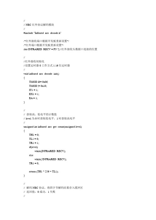
//---------------------------------------------// NEC红外协议解码模块//---------------------------------------------#include "Infrared_nec_decode.h"/*红外接收端口根据开发板重新设置*//*红外端口根据开发板重新设置*/sbit INFRARED_RECV = P3^2;//红外接收头数据口连接的位置//---------------------------------------------//红外接收初始化//设置定时器0工作方式1 16位定时器//---------------------------------------------void infrared_nec_decode_init(){TMOD &= 0x0f;TMOD |= 0x10;IT1 = 1;EX1 = 1;EA = 1;}//---------------------------------------------// 获取高、低电平的计数值// level为0时获取低电平,1时获取高电平//---------------------------------------------unsigned int infrared_nec_get_count(unsigned level){TH1 = 0;TL1 = 0;TR1 = 1;if(level)while(INFRARED_RECV);elsewhile(!INFRARED_RECV);TR1 = 0;return (TH1 * 256 + TL1);}//---------------------------------------------// 解码NEC协议,将四字节解码结果存入缓冲区// 返回值:0成功,1失败//---------------------------------------------unsigned char infrared_nec_get_code(unsigned char* buf){unsigned int count = 0; //定时器计数unsigned char i, j;//计算是否为引导码count = infrared_nec_get_count(0); //引导脉冲低电平8500~9500usif(count < 7372 || count > 9216)return 1;count = infrared_nec_get_count(1); //引导脉冲高电平4000~5000us if(count < 3686 || count > 4608)return 1;for(i = 0; i < 4; i++) //4个字节{for(j = 0; j < 8; j++) //每个字节8位{count = infrared_nec_get_count(0); //200~800usif(count < 184 || count > 737)return 1;count = infrared_nec_get_count(1); //200~2000usif(count < 184 || count > 1843)return 1;buf[i] >>= 1;if(count > 1032)buf[i] |= 0x80;}}return 0;}。
基于NEC协议的遥控系统仿真设计

基于NEC协议的遥控系统仿真设计作者:卿玉明来源:《电脑知识与技术》2017年第01期摘要:根据NEC红外遥控协议的特性,采用Proteus提供的红外信号处理模块IRLINK,设计出一种红外遥控仿真系统。
对系统硬件和相应的软件进行分析并给出流程图和关键代码,实现对短时按键和长时按键的编码显示和相应功能控制。
通过单片机的定时器配合使用,对红外遥控信号的下降沿进行判断,以适应不同的实际遥控发射电路,从而不用区分信号高低电平细节,稍加修改就可适应众多的遥控协议。
关键词:NEC协议;IRLINK;Proteus;仿真中图分类号:TP871 文献标识码:A 文章编号:1009-3044(2017)01-0016-03Abstract: According to the characteristics of NEC infrared remote control protocol, IRLINK is used to design a kind of infrared remote control simulation system based on Proteus. Analyze the hardware and software of the system and give the flow chart and key code, realize the encoding display and the corresponding function control of the short key and the long time. Through the MCU timer with the use of infrared remote control signal decreased along the judge, to adapt to different practical remote control transmitter, which do not distinguish between high and low signal level detail, slightly modified can adapt to numerous remote protocol.Key words: NEC protocol; IRLINK; Proteus; Simulation在通信距离要求不高的场合,红外的成本比其他无线设备要低的多。
红外遥控协议分析之:NEC协议
红外遥控编码传输协议生产厂家对红外遥控的编码做了严格的规范,目前国内外主流的红外遥控编码传输协议有十多种,女口 NEC 、Philips RC-5、Philips RC-6、Philips RC-MM 、Philips RECS80、 RCA 、 X-Sat 、ITT 、JVC 、Sharp 、Nokia NRC17 和 Sony SIRC 等。
国内最常用的规范有两种: NEC 和Sony SIRC 。
这两种规范的调制方式分别为: PPM(脉冲间隔调制)和PWM (脉冲宽度调制)。
谈到这两个概念,我需要具体讲解一下,因为我在 网上查阅相关资料时甚是郁闷,好多说法相互矛盾。
有说NEC 属于PWM 的因为它的脉宽 不同,PPM 的脉宽是固定的。
而细心地朋友如果探究到 NEC 的典型芯片的芯片手册时,会发现上面这种说法是错误的。
比如 UPD6121这款红外远程控制芯片的调制方式为PPM 。
后来终于在一家国外的网站上找到了能够自圆其说的解释。
个人认为比较正确,拿来和大家分享。
要想认清红外遥控编码传输协议的具体内容,我想还是先捡其重点来讲一下, 编码规范中最重要的当属调制这部分了。
而主流的调制方式有两种分别为 PPM 和PWM ,当然其他 还有好几种,这里先不讲解,免得糊涂了。
本文就先介绍下 PPM 和PWM 的区别。
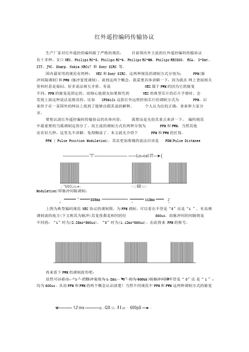
PPM ( Pulse Position Modulation),其实更加准确的说法应该是PDM(Pulse DistaneeModulation)即脉冲间隔调制:------ :----- 225ms ------------- ------- 112ms ---- IE33上图为典型编码规范 NEC 协议的调制图,为PPM 调制。
可以看出不管是“0”还是“1 ”, 有高频调制波的地方(下文称其为脉冲)其宽度都是相同的位560us ,而脉冲间的间隔则是不同的:“1”时为(2.25ms-560us),“0”时为(1.12ms-560us)。
红外遥控协议分析之:NEC协议

红外遥控编码传输协议生产厂家对红外遥控的编码做了严格的规范,目前国内外主流的红外遥控编码传输协议有十多种,如NEC、Philips RC-5、Philips RC-6、Philips RC-MM、Philips RECS80、 RCA、X-Sat、ITT、JVC、Sharp、Nokia NRC17和Sony SIRC等。
国内最常用的规范有两种:NEC和Sony SIRC。
这两种规范的调制方式分别为:PPM(脉冲间隔调制)和PWM(脉冲宽度调制)。
谈到这两个概念,我需要具体讲解一下,因为我在网上查阅相关资料时甚是郁闷,好多说法相互矛盾。
有说NEC属于PWM的因为它的脉宽不同,PPM的脉宽是固定的。
而细心地朋友如果探究到NEC的典型芯片的芯片手册时,会发现上面这种说法是错误的。
比如UPD6121这款红外远程控制芯片的调制方式为PPM。
后来终于在一家国外的网站上找到了能够自圆其说的解释。
个人认为比较正确,拿来和大家分享。
要想认清红外遥控编码传输协议的具体内容,我想还是先捡其重点来讲一下,编码规范中最重要的当属调制这部分了。
而主流的调制方式有两种分别为PPM和PWM,当然其他还有好几种,这里先不讲解,免得糊涂了。
本文就先介绍下PPM和PWM的区别。
PPM(Pulse Position Modulation),其实更加准确的说法应该是PDM(Pulse Distance Modulation)即脉冲间隔调制:上图为典型编码规范NEC协议的调制图,为PPM调制。
可以看出不管是“0”还是“1”,有高频调制波的地方(下文称其为脉冲)其宽度都是相同的位560us,而脉冲间的间隔则是不同的:“1”时为(2.25ms-560us),“0”时为(1.12ms-560us)。
由此得来PPM的称号。
再来看下PWM的调制波形吧:显然可以看出,“1”的脉冲宽度为1.2ms,“0”的为600us。
而脉冲间隔不管是“0”还是“1”,均为600us。
红外线遥控器(nec编码方式)介绍

學習型遙控器的分類
優點:可以使用任何遙控器的學習,無須更新代碼程式即可使用目前所有 乃至未來的所有紅外線遙控的學習。
缺點:對主控制晶片和記憶體的選擇都比固定式要高。整體成本上較貴於 固定碼式學習型遙控器
FAE Service Department designed
Data Memory
I/ O
8bit
16bit
Ext.
Int.
IR Carrier
LVR
PFD Stack
400kHz
~
15
2.0V
4MHz
~
1Kx14
32x8
--
--
--
--
v
v
--
1
3.6V
4MHz
16
Package 20SSOP
HT48RA0-1 HT48CA0-1
HT48RA1 HT48CA1
NEC碼分析
在東亞地區比較常用的紅外線傳輸協議是NEC協議,故我們主要介紹NEC 協議即6122協議。 1. 協議組成:
引導碼,16bit用戶碼(地址碼),8bit命令碼(數據碼)及其反碼。
• 引导码由一个9ms的载波波形和4.5ms的关断时间构成 ‚ 地址碼共16bit,低8位在前,高8位在后。 ƒ 8bit命令碼及其反碼
20x4
32x4
HT49RA1 HT49CA1
2.0V ~
3.6V
4MHz
4Kx15
160x8
8
,
8
33x3 4
,
8
1
1
v
2
4
v
v
红外遥控NEC解码程序

//=============================///********************************本解码程序完成于2017.07.29日,看起来不难,却花了我很多心思。
今我愿与网友分享此代码,希望能帮助跟我一样的初学者!!!此代码中定时器使用的是STC89C52的定时计数器2,位16位自动重装定时器。
此代码解码后解码数据显示在串口工具上。
********************************///=============================///********************************西安石油大学:王普********************************///=============================//#include <reg52.h>typedef unsigned char uchar;uchar count;uchar wedat[33];uchar dat[4];bit receive_flag , chuli_data_ok;sbit bus=P3^2;void init(){TMOD=0x22;//定时器1,0都是8位自动重装寄存器RCAP2H=0xfe;RCAP2L=0xff;TH2=(65535-256)/256;TL2=(65535-256)%256;EA=1;ET2=1;IT0=1; //红外外部中断EX0=1; //外部中断允许位TH1 = 0xfd; //此溢出率为波特率9600TL1 = 0xfd;TR1 = 1; //启动定时器1SM0 = 0;SM1 = 1; //设置串口工作方式1,10位异步收发器}void timer0() interrupt 5{TF2=0;count++;}void EX_INT0() interrupt 0//红外遥控信号进入中断服务程序{static uchar num;//静态变量,每次进入其值不变,num是每个脉宽的编号static uchar flag,flag1; //辅助标志位TR2=1;//当IT0下降沿发生,脉宽进入,打开定时器2if(flag == 1)//第一次flag=0,不执行下面程序,直接出中断程序,下次进入执行{if(( count < 60) && (count >= 40) )//检测起始码宽度,符合条件进入{num=0;//起始码编号为0,存入数组中flag1=1;//辅助标志位,用于进入下面程序}}if(flag1==1)//第二次进入中断后将33和脉宽依次存入数组中,编号为0~32 {wedat[num] = count; //读取T2定时器中断程序中的计数值count = 0;//都去完成后,清零num++;//编号++}flag=1;//第一次flag=0,第二次进入后为1,开始执行脉宽存储程序if(num > 32)//如果num大于32,也就是说33个脉宽都存入了,0~32,共33个。
NEC协议的红外遥控器驱动程序

是不是觉得红外遥控 +51单片机是绝妙组合?但是在编程时才发现超级纠结?其实也 没那么纠结,自己摸索摸索,总能找出办法来的。
本程序占用了 51单片机的定时器 0以及中断1两个资源,为的是使单片机能接收到每 一个红外脉冲信号, 一个都不能少。
如果舍不得用这两个资源,还有另一种查询的办法,就 是不一定每个信号都能收到,可自己琢磨一下。
需要全套NEC 协议红外遥控器资料的,到网上找,到处都有,而且很全。
另外,对着资料写程序如果实在写不出,可以找个示波器,把波形录下来好好研究研 究。
毕竟有些时候资料会过时,只要里面有一点东西变化了, 程序就完全不一样了。
这种弯 路,尽量少走。
本程序只是头文件,具体到应用上还要各位自己动脑筋了,希望对大家有所帮助。
共 同学习,共同进步! 69 70 71 68 64 67 07 21 09 22 25 13 12 24 94 08 28 90 66 82 74 NEC 协议的红 外遥控器按 键对应数字 一览/******************************************************************INF_NEC.h用于NEC 协议的遥控器,主控器为 51单片机。
用户码8位,分布于2-17个脉冲;按键码8位,分布于18-33个脉冲。
皆为前8原码,后8反码。
注意:本驱动占用 51单片机的外部中断1以及定时器0两个资源,编程时注意 不要再乱动这两个资源。
*******************************************************************/#in clude<reg52.h> #defi ne uchar un sig ned char#defi ne uint un sig ned intuchar nec_cod[2]={0,1};〃遥控器的编号,编号 uchar nec_dat[2]={0,1};〃遥控器的数据,数据 #ifndef __INF_NEC_#defi ne __INF_NEC extern void n ec_i nit(); extern void n ec_act();#en difvoid nec_init() //外中断1及定时器0的初始化函数{TMOD=(TMOD&0xf0)|0x02; // 定时器0模式2,8位自动重装//11.0592MHz 晶振,计数 230次,大概时间 250us//定时器0使能,先关着〃外部中断1使能,用来接收红外信号〃开总中断void nec_act()//按键功能程序{if(( nec_dat[0]==~ nec_dat[1]) &&(n ec_flag==3)){switch( nec_dat[0]){case 69: break;case 70: break;case 71: break;case 68:break;case 64:break; uchar nec_flag=0;//nec_flag:遥控码的标志位。
- 1、下载文档前请自行甄别文档内容的完整性,平台不提供额外的编辑、内容补充、找答案等附加服务。
- 2、"仅部分预览"的文档,不可在线预览部分如存在完整性等问题,可反馈申请退款(可完整预览的文档不适用该条件!)。
- 3、如文档侵犯您的权益,请联系客服反馈,我们会尽快为您处理(人工客服工作时间:9:00-18:30)。
N E C协议的红外遥控
器驱动程序
WEIHUA system office room 【WEIHUA 16H-WEIHUA WEIHUA8Q8-
是不是觉得红外遥控+51单片机是绝妙组合?但是在编程时才发现超级纠结?其实也没那么纠结,自己摸索摸索,总能找出办法来的。
本程序占用了51单片机的定时器0以及中断1两个资源,为的是使单片机能接收到每一个红外脉冲信号,一个都不能少。
如果舍不得用这两个资源,还有另一种查询的办法,就是不一定每个信号都能收到,可自己琢磨一下。
需要全套NEC协议红外遥控器资料的,到网上找,到处都有,而且很全。
另外,对着资料写程序如果实在写不出,可以找个示波器,把波形录下来好好研究研究。
毕竟有些时候资料会过时,只要里面有一点东西变化了,程序就完全不一样了。
这种弯路,尽量少走。
本程序只是头文件,具体到应用上还要各位自己动脑筋了,希望对大家有所帮助。
共同学习,共同进步!
/****************************************************************** 用于NEC协议的遥控器,主控器为51单片机。
用户码8位,分布于2-17个脉冲;
按键码8位,分布于18-33个脉冲。
皆为前8原码,后8反码。
注意:本驱动占用51单片机的外部中断1以及定时器0两个资源,编程时注意不要再乱动这两个资源。
*******************************************************************/ #include<>
#define uchar unsigned char
#define uint unsigned int
uchar nec_flag=0;//nec_flag:遥控码的标志位。
0:无信号;1、2:信号采集;3、可用信号
uchar nec_num=0;//nec_num:红外码的序号
uint nec_time=0;//nec_time:定时器的计时次数nec_time*250us
uchar nec_cod[2]={0,1};//遥控器的编号,编号0为原码,编号1为反码
uchar nec_dat[2]={0,1};//遥控器的数据,数据0为原码,数据1为反码
#ifndef __INF_NEC__
#define __INF_NEC__
extern void nec_init();
extern void nec_act();
#endif
void nec_init() //外中断1及定时器0的初始化函数
{
TMOD=(TMOD&0xf0)|0x02; //定时器0模式2,8位自动重装
TH0=0x19;
TL0=0x19; //晶振,计数230次,大概时间250us ET0=1;TR0=0; //定时器0使能,先关着
IT1=1;EX1=1; //外部中断1使能,用来接收红外信号
EA=1; //开总中断
}
void nec_act()//按键功能程序
{
if((nec_dat[0]==~nec_dat[1])&&(nec_flag==3))
{
switch(nec_dat[0])
{
case 69: break;
case 70: break;
case 71: break;
case 68:break;
case 64:break;
case 67:break;
case 7:break;
case 21:break;
case 9:break;
case 22:break;
case 25:break;
case 13:break;
case 12:break;
case 24:break;
case 94:break;
case 8:break;
case 28:break;
case 90:break;
case 66:break;
case 82:break;
case 74:break;
}
}
}
void timer0(void) interrupt 1
{
nec_time++;
if(nec_time>1000)//长时间无红外遥控信号时关定时器
{
nec_time=0;nec_num=0;nec_flag=0;TR0=0;
}
}
void exint1(void) interrupt 2
{
uint intime=0;//intime:为了不打扰计时器工作,所以用intime把nec_time 提出来
intime=nec_time;nec_time=0;//nec_time置0,准备计数
if(nec_num==0)TR0=1;//开定时器,开始计数
if(nec_num==1){if((intime>50)&&(intime<60))nec_flag=1;}
if(nec_num==2){if((intime>2)&&(intime<11))nec_flag=2;}
if(nec_flag==2)
{
if((nec_num>=2)&&(nec_num<=9))
{
if((intime>2)&&(intime<6))nec_cod[0]=nec_cod[0]&~(0x01<<(nec_num-2));
else
if((intime>7)&&(intime<11))nec_cod[0]=nec_cod[0]|(0x01<<(nec_num-2));
}
if((nec_num>=10)&&(nec_num<=17))
{
if((intime>2)&&(intime<6))nec_cod[1]=nec_cod[1]&~(0x01<<(nec_num-10));
else
if((intime>7)&&(intime<11))nec_cod[1]=nec_cod[1]|(0x01<<(nec_num-10));
}
if((nec_num>=18)&&(nec_num<=25))
{
if((intime>2)&&(intime<6))nec_dat[0]=nec_dat[0]&~(0x01<<(nec_num-18));
else
if((intime>7)&&(intime<11))nec_dat[0]=nec_dat[0]|(0x01<<(nec_num-18));
}
if((nec_num>=26)&&(nec_num<=33))
{
if((intime>2)&&(intime<6))nec_dat[1]=nec_dat[1]&~(0x01<<(nec_num-26));
else
if((intime>7)&&(intime<11))nec_dat[1]=nec_dat[1]|(0x01<<(nec_num-26));
}
}
nec_num++;if(nec_num>35){nec_num=35;nec_flag=3;}
}。