NORTE北电中文手册
(精选文档)NORTEL北电中文手册

LD 10PBX 电话机管理提示和响应-LD 10标号提示响应注释1 REQ 请求CHG 修改现有的数据块CPY n 从指定的分机数据块自动拷贝或生成1至32个新的分机数据块对Option 11各模式无效,版本12和其后的软件。
END 退出覆盖程序MOV 将数据块从一个TN移到另一个。
对Option 11各模式无效。
NEW X 增加新的数据块NEW后是一个1-255的数值,以生成此数目的接连的电话机数据块OUT X 取消数据块OUT后是一个1-255的数值,以取消此数目的接连的电话机数据块2 TYPE 数据块类型500500/2500电话机数据块500 M7Option 11的500/2500模式电话机数据块CARD 自动话机移位(ASR)的500/2500卡板块CARDSLT 单线电话机用户线卡板(版本19和其后的软件)OOSSLT20停止运行单线终端单元3 MODL71-127 模式号码,对Option 11模式话机提示。
4 CFTN 1 s c u 从TN拷贝,在REQ=CPY时提示。
c u7用于Option11,用这个TN作为新话机的样板。
5 SFMT 对拷贝命令选用以下一种格式,在CLS=AGTA时,提示POS。
D N输入项可长达4位,配备DNXP软件包150则长达7位TNDN 人工选择TN,DN和ACD电话机的ACD座席IDTN,DN和POS提示-n-次,如在CPY命令中所规定。
TN l s c u 新话机的TNDN xxxx 新话机的DNPOS xxxx ACD座席IDTN 新DN和ACD电话机的ACD座席ID是由系统提供的,对您提示要求开始的DN,ACD座席ID和每一个TN。
TN提示n次,如在CPY命令中所规定。
DN xxxx 新话机的DNPOS xxxx ACD座席IDTN l s c u 新话机的TNDN 新TN都是由系统提供的,对您提示要求开始的TN和每一个DN以及ACD电话机的ACD座席ID。
nortel 3902数字话机培训
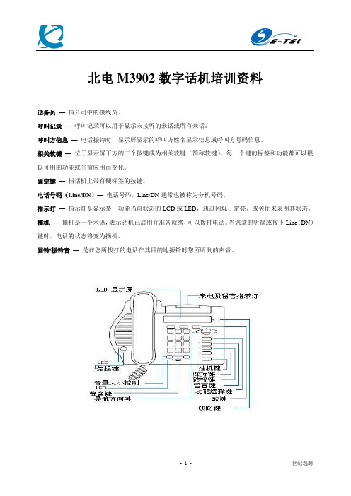
北电M3902数字话机培训资料话务员—指公司中的接线员。
呼叫记录—呼叫记录可以用于显示未接听的来话或所有来话。
呼叫方信息—电话振铃时,显示屏显示的呼叫方姓名显示信息或呼叫方号码信息。
相关软键—位于显示屏下方的三个按键成为相关软键(简称软键)。
每一个键的标签和功能都可以根据可用的功能或当前应用而变化。
固定键—指话机上带有硬标签的按键。
电话号码(Line/DN)—电话号码,Line/DN通常也被称为分机号码。
指示灯—指示灯是显示某一功能当前状态的LCD或LED,通过闪烁、常亮、或关闭来表明其状态。
摘机—摘机是一个术语,表示话机已启用并准备就绪,可以拨打电话。
当您拿起听筒或按下Line(DN)键时,电话的状态将变为摘机。
回铃/振铃音—是在您所拨打的电话在其目的地振铃时您所听到的声音。
话机控制界面功能操作打电话要打电话,请使用如下步骤最后号码重拨功能使您得以自动重拨最后所拨打的号码。
在免提呼叫中使用最后号码重拨功能:回振铃功能拨内线分机号后听到忙音或无人接听时,可以使用回振铃功能。
回振铃功能可以使您得知对方电话何时不再占线或在使用当中。
从而及时提醒您重拨对方号码。
回振铃功能会自动重拨号码。
使用回振铃功能一旦对方线路空闲或对方再次使用话机并挂机后,您将立即听到回振铃提示音,而且屏幕将显示Party free,select line 。
接听到提示音后,要呼叫回振铃一方:在听到提示音之前取消回振铃功能:自动拨号自动拨号功能使用户只需按一个功能键(自动拨号键)就可以自动拨打特定的电话号码。
存储自动拨号号码使用自动拨号功能热线功能电话系统管理员可以设定一个Hot Line 键,以方便您自动拨打一个特定的号码。
接听电话当有来电时,话机振铃,并且相应的LCD 指示灯闪烁接听或者呼叫保持在与一方通话时,您可以使用保持功能将对方处于保持状态中。
使呼叫转入保持状态恢复所保持的呼叫呼叫转接在通话过程中使用转接功能可以将呼叫转接到第三方 使用转接功能在转接未成功时重新接通主叫方呼叫代答功能:使用呼叫代答功能,您可以代答在同一个代答组内的其他正在振铃的话机。
中文低压钠灯控制器说明书20060912-纯光电[1]
![中文低压钠灯控制器说明书20060912-纯光电[1]](https://img.taocdn.com/s3/m/39f576c60c22590102029dfe.png)
使用说明:充、放电及保护:通常蓄电池电压在正常范围时,状态指示灯为绿色常亮;充满后状态指示灯为绿色慢闪;当电池电压降低到欠压时状态指示灯变成橙黄色;当蓄电池电压继续降低到过放电压时,状态指示灯变为红色,此时控制器将自动关闭输出,提醒用户及时补充电能。
当电池电压恢复到正常工作范围内时,将自动使能输出开通动作,状态指示灯变为绿色;如果用户使用的负载侧出现开路、短路等故障时,控制器将关闭输出,状态指示灯为红色闪烁,提示用户检查负载,重新连接蓄电池或等到第二天可以正常工作,状态指示灯恢复正常指示;如果发生过过放动作,充电先要达到提升充电电压,并保持几分钟,而后降到直充电压保持几分钟,以活激蓄电池,避免硫化结晶,最后降到浮充电压并保持。
如果没有发生过放,将不会有提升充电方式,以防蓄电池失水。
这些自动控制过程将使蓄电池达到最佳充电效果并保证或延长其使用寿命。
当系统电压超出工作电压最大值3V 将关断输出,保护电路。
光感应启动点的设置及校正:使用面板上的设置按键(start set ),可根据合适的室外亮度设定和修改输出的启动时间,设置后将存入该启动点至存贮器,以后将按此设定点的室外光照度启动或关闭输出。
设置过程:根据天的亮度,选择要启动输出的时间,用笔尖按下该按钮连续10秒钟,系统状态指示等闪烁,迅速松开,在5秒内再次按下该按键(如果不操作将不会改变原启动点),灯停闪,此时控制器已记忆该启动照度。
注意,控制器的10分钟确认启动信号的延时始终会存在。
纯光控方式:当没有阳光时,光强降到启动点,控制器延时10分钟确认启动信号后,开通负载,负载开始工作;当有阳光时,光强升到启动点,控制器延时10分钟确认关闭输出信号后关闭输出,负载停止工作。
光控+延时方式:启动过程同前。
当负载工作到设定的时间就关闭负载,时间设定见下表。
24小时连续工作方式:此方式为灯全天常亮,只有过放、故障发生才关闭,仅无光控、定时,保留其它所有功能。
北电Alteon应用层交换机技术手册_EMS 3.1.2 Release Notes

4655 Great America ParkwaySanta Clara, CA 95054Phone 1-800-4NortelAlteon EMS 3.1.2.0Release Notespart number: 216623-C, January 2005Alteon EMS 3.1.2.0 Release Notes2216623-C, January 2005Copyright 2005 Nortel Networks, Inc.,4655 Great America Parkway, Santa Clara, California 95054, USA. All rights reserved. Part Number: 216623-C.This document is protected by copyright and distributed under licenses restricting its use, copying, distribution, and decompilation. No part of this document may be reproduced in any form by any means without prior written authorization of Nortel Networks, Inc. Documentation is provided “as is” without warranty of any kind, either express or implied, including any kind of implied or express warranty of non-infringement or the implied warranties of merchantability or fitness for a particular purpose.U.S. Government End Users: This document is provided with a “commercial item” as defined by FAR2.101 (Oct 1995) and contains “commercial technical data” and “commercial software documentation” as those terms are used in FAR 12.211-12.212 (Oct 1995). Government End Users are authorized to use this documentation only in accordance with those rights and restrictions set forth herein, consistent with FAR 12.211- 12.212 (Oct 1995), DFARS 227.7202 (JUN 1995) and DFARS 252.227-7015 (Nov 1995).Nortel Networks, Inc. reserves the right to change any products described herein at any time, and without notice. Nortel Networks, Inc. assumes no responsibility or liability arising from the use of productsdescribed herein, except as expressly agreed to in writing by Nortel Networks, Inc. The use and purchase of this product does not convey a license under any patent rights, trademark rights, or any other intellectual property rights of Nortel Networks, Inc.Alteon EMS , Alteon 2424, Alteon 2424-SSL, Alteon 2224, 2216, 2208, 3408, Alteon 180, Alteon 180e, Alteon 184, Alteon AD3, Alteon AD4, and ACEswitch are trademarks of Nortel Networks, Inc. in the United States and certain other countries. Cisco ® and EtherChannel ® are registered trademarks of Cisco Systems, Inc. in the United States and certain other countries. Check Point ® and FireWall-1® aretrademarks or registered trademarks of Check Point Software Technologies Ltd. Any other trademarks appearing in this manual are owned by their respective companies.Originated in the U.S.A.Release NotesThese release notes provide the latest information about the Alteon ElementManagement System (Alteon EMS) software. This document supplements theexisting software documentation.Please keep this information with your Alteon product manuals.Installing Alteon EMSTo install Alteon EMS, follow the instructions provided on-screen during the initialsetup wizard. This setup should run automatically when the Alteon EMS CD-ROM is insertedinto the CD drive of the computer. If it does not, run install.exe (Windows) orinstall.bin (UNIX) manually from the operating system.N OTE – For optimal performance, Nortel Networks recommends that previous versions ofAlteon EMS be uninstalled before upgrading to this new version.GUI Installation using InstallAnywhereInstallAnywhere, a GUI installation tool, is available for Windows, Linux RedHat 8.0 andSolaris (Sparc)platforms. By default, Alteon EMS is installed on the primary drive in theapplications directory. For example, on a Windows computer, Alteon EMS would be installedby default in the directory C:\Program Files\AlteonEMS.For more information, refer to the document InstallDoc.html.3 216623-C, January 2005Alteon EMS 3.1.2.0 Release Notes4216623-C, January 2005InstallAnywhere has been verified on the following operating systems: Solaris (Sparc) 2.7 and 2.8 RedHat Linux 8.0 or 9.0 Windows 98 Windows NT4 (Service Pack 6a is recommended) Windows 2000 (Service Pack 4 is recommended) Windows XP N OTE – If the Alteon EMS Server is being installed, refer to Alteon Intelligent Traffic Management Installation Guide (Part Number 216391-A rev 01) for hardware requirements before performing this task.Program Requirements This section lists the minimum requirements necessary for running Alteon EMS 3.1.2.Hardware Requirements Alteon EMS 3.1.2 supports the following switch platforms: Alteon Application Switch 2000 and 3000 series (Alteon 2208, 2216, 2224, 2424, 2424-SSL, and 3408) Alteon 180 series (Alteon 180e, Alteon 184) Alteon AD series (Alteon AD3, Alteon AD4) Alteon Link Optimizer (ALO) 143 and 150Switch Software Requirements Alteon EMS 3.1.2 requires the switch platform to meet the following minimum software requirements: ALO OS 1.1.1.0 (or higher) on the Alteon Link Optimizer Web OS 8.3.22.3 (or higher), 9.0.35 (or higher), or 10.0.25 and higher on Alteon Web switches Alteon OS 20.0 and higher on series 2000 and 3000 Alteon Application SwitchesAlteon EMS 3.1.2.0 Release Notes5216623-C, January 2005N OTE – Alteon EMS will give notification if an unsupported version of software is running on the switch. In such an instance, try Alteon EMS 1.3 on any Web switch running Web OS 10.0 or higher.Client System RequirementsAlteon EMS 3.1.2 requires the client computer to meet the following minimum hardware and software requirements:Memory: 128MB Hard Drive Space:70MB on Solaris or RedHat Linux 8.0 or 9.0 60MB on WindowsRecommended Screen Resolution: 1280 x 1024 Java Virtual Machine (JVM) 1.4.2 (Installed with Alteon EMS)Switch Access Through TelnetIt may be necessary to access the switch through telnet during an Alteon EMS session to make use of command line interface (CLI) commands. A telnet connection can be made to the switch in Alteon EMS by following these steps:1.Click the Telnet icon in the Alteon EMS menu bar.2.In the Telnet window, enter the IP address of the switch.3.Enter the switch password.4.Enter the desired CLI commands at the prompt.Known Software LimitationsAlteon EMS Does Not Support Serial DownloadsThe use of serial software downloads is only supported through the command line interface (CLI). For more information on this topic, please see the Alteon OS 22.0.2Command Reference (Part Number 315393-J).Alteon EMS 3.1.2.0 Release Notes6216623-C, January 2005Alteon EMS Does Not Support Some CLI Commands Alteon EMS does not support the use of some CLI commands or equivalents. To access these commands, open a Telnet session to the switch. See “Switch Access Through Telnet” for more details.The following commands cannot be issued through Alteon EMS: On 2000 series Alteon Web Switches: /oper/swkey /oper/rmkey /oper/ip/bgp/start /oper/ip/bgp/stop /cfg/sys/access/tnet /cfg/sys/access/http /cfg/sys/access/https /cfg/sys/snmp On 180 series Alteon Web Switches: diff /oper/swkey /oper/rmkey /oper/ip/bgp /cfg/sys/tnport /cfg/sys/tnet /cfg/sys/http /cfg/sys/snmp SONMP Support Changes If you do not use SONMP (Nortel’s proprietary discovery protocol), disregard the following.Changes have been made in the area of SONMP that makes Alteon EMS 2.3.3 incompatible with versions of Alteon OS 21.0.2 and earlier. For switches running versions up to Alteon OS 21.0.2, Nortel Networks recommends the use of Alteon EMS 2.3.2 or the configuration of SONMP through the CLI.Alteon EMS 3.1.2.0 Release Notes7216623-C, January 2005Alteon EMS No Longer Supports Integration with the Optivity Integration ProductAlteon EMS no longer supports integration with Nortel Networks Optivity products. To obtain a Nortel Optivity Integration OIT file, download the proper OIT file for the supported Optivity product and perform a manual install.For more information about Optivity products, and where to download OIT files, contact your Nortel Networks customer service representative.Alteon EMS and Health ScriptsThe display and modification of health scripts is supported only on selected Alteon Web Switches. See the table below to determine on which models this feature is available.For switches that do not support health script display and modification, use the CLI to perform these tasks.Configuration Finalization In Alteon 180 and AD series If a configuration fails through Alteon EMS in 180 and AD series switches, it is necessary to use the apply command in the CLI to finalize the configuration.If this same situation arises in 2000 or 3000 series switches, an error message will be generated in the console.Apparent Timeout On Configuration SaveWhen a new switch configuration is saved in Alteon EMS, confirmation is usually given with the message New Configuration successfully saved to flash . In some instances however a timeout error is generated if the Save action takes four minutes or 48 times the user specified timeout, whichever is longer. While the configuration was most likely saved to the flash, EMS may stop monitoring the action after the timeout threshold has been reached.Table 0-1 Alteon EMS Health Script SupportHealth Script SupportAvailableHealth Script Support Unavailable Alteon 2000 seriesAlteon 3000 series Alteon 180 series Alteon AD seriesAlteon EMS 3.1.2.0 Release Notes8216623-C, January 2005To confirm that the Save action has been successful, Telnet to the switch and enter the Save command. If the system message No save needed is shown, the configuration has been saved to the flash memory.Clearing Statistics On 180 and AD series Alteon Switches Alteon EMS clears only the counter for the particular EMS window session. Exiting the Monitor window and re-entering it reverts the counter to reflect the actual switch counter.You may use the Alteon EMS Clear Statistics button on 2000 series switches, at the bottom of most Monitor windows, to clear statistics from the switch as puter “Lock Up” Using Windows and Alteon EMS If your computer “locks up” after closing Alteon EMS in a Windows environment, follow these steps to mitigate the problem in the future:1.Perform a hard or soft reboot of the computer.2.Go to the Display Properties settings.Access these settings by navigating to the Windows Control Panel and selecting the Display icon.3.Select the Settings tab and click the Advanced button.4.Select the Troubleshoot tab.5.Move the Hardware Acceleration slider control until it points to None (the far left-hand side).This procedure mitigates a known defect in the Java Virtual Machine that can cause conflicts with some graphics controller cards.N OTE – Use of version 1.4.2 of the Java Virtual Machine can further mitigate this defect. To download this version of the Java Virtual Machine visit the Sun Microsystems web site.Alteon EMS 3.1.2.0 Release Notes9216623-C, January 2005Mouse Clicks in Graph WindowsWindows 95, 98, and Millennium Edition (ME) may experience a limitation where mouse clicks are not recognized on graph windows in Alteon EMS. This is a known limitation of the Java 2 Runtime Environment.To mitigate this limitation, follow this procedure:1.Download and install the Tweak UI product from the Microsoft web site.2.Run Tweak UI after installation.3.Select the General tab and de-select the Mouse hot track effects option.4.Save the change.N OTE – Tweak UI is not a supported Microsoft product and Microsoft assumes no liability or guarantees.Netscape Required For Solaris Online HelpOnline help files can only be viewed when running Alteon EMS on the Solarisoperating system through the Netscape browser. This is a known limitation reported by Sun Microsystems.To view online help, open the Netscape browser before clicking the Help button in Alteon EMS.Multiple Help Windows Open in Some Windows Versions In some Windows 9x, NT, and Windows 2000 systems, a separate browser window may open each time the Help button is clicked in Alteon EMS.To change this behavior, follow the procedure appropriate to the Windows version being used:Windows 9x and NT1.Open My Computer from the desktop.2.Select the menu: View > Folder > Folder Options > File Types .3.Find HTML Document in the Registered File Types window.4.Change the Action to Open In The Same Window .Alteon EMS 3.1.2.0 Release Notes10216623-C, January 20055.Click the Set Default button.6.Click OK .Windows 20001.Open My Computer from the desktop.2.Select the menu: Tools > Folder Options > File Types .3.Find HTML Document in the Registered File Types window.4.Click the Advanced button.5.Change the Action to the Open option.6.Click the Set Default button.7.Click OK .Screen Distortion Some distortion can occur in the Alteon EMS windows if the display properties are set to 24-bit color in combination with the use of graphic intensive applications. This distortion typically takes the form of screen artifacts in the active window. To avoid this behavior, change the display properties to 16-bit color or force a repaint of your display. For information about display settings and other graphic issues, refer to your operating system manual.N OTE – This behavior may not occur if version 1.4.2 or higher of the Java Virtual Machine is installed.。
北电文档212486-C_00

Part No. 212486-C Rev 00May 20064655 Great America ParkwaySanta Clara, CA 95054Adding MAC Addresses to the Ethernet Routing Switch 8000 Series ChassisCopyright © Nortel Networks 2006. All Rights Reserved.The information in this document is subject to change without notice. The statements, configurations, technical data, and recommendations in this document are believed to be accurate and reliable, but are presented without express or implied warranty. Users must take full responsibility for their applications of any products specified in this document. The information in this document is proprietary to Nortel Networks.Trademarks*Nortel, Nortel Networks, the Nortel Networks logo, and the Globemark are trademarks of Nortel Networks.Microsoft, Windows, and Windows NT are trademarks of Microsoft Corporation. The asterisk after a name denotes a trademarked item.Statement of ConditionsIn the interest of improving internal design, operational function, and/or reliability, Nortel Networks Inc. reserves the right to make changes to the products described in this document without notice.Nortel Networks Inc. does not assume any liability that may occur due to the use or application of the product(s) or circuit layout(s) described herein.How to get HelpThis section explains how to get help for Nortel* products and services.Getting Help from the Nortel Web siteThe best way to get technical support for Nortel products is from the Nortel Technical Support Web site:/supportThis site provides quick access to software, documentation, bulletins, and tools to address issues with Nortel products. More specifically, the site enables you to:•download software, documentation, and product bulletins •search the Technical Support Web site and the Nortel Knowledge Base for answers to technical issues•sign up for automatic notification of new software and documentation for Nortel equipment•open and manage technical support casesGetting Help over the phone from a Nortel Solutions CenterIf you don’t find the information you require on the Nortel Technical Support Web site, and have a Nortel support contract, you can also get help over the phone from a Nortel Solutions Center.In North America, call 1-800-4NORTEL (1-800-466-7835).Outside North America, go to the following Web site to obtain the phone number for your region:/callusGetting Help from a specialist by using an Express Routing CodeTo access some Nortel Technical Solutions Centers, you can use an Express Routing Code (ERC) to quickly route your call to a specialist in your Nortel product or service. To locate the ERC for your product or service, go to:/ercGetting Help through a Nortel distributor or resellerIf you purchased a service contract for your Nortel product from a distributor or authorized reseller, contact the technical support staff for that distributor or reseller.This document describes how to upgrade the media access control (MAC) addresses to a total of 4096 MAC addresses on the following Ethernet Routing Switch 8000 Series chassis:•Ethernet Routing Switch 8010co•Ethernet Routing Switch 8010•Ethernet Routing Switch 8006Your MAC address kit contains:•an Additional MAC Addresses License• 2 labels printed with the base MAC address of your new block of MAC Addresses•DocumentationThis document discusses the following topics:Topic Page number Before you start next Installing MAC addresses using the CLI6Installing MAC addresses using the NNCLI (8300 only)9Using the CLI to display the base MAC address1214Using the NNCLI to display the base MAC address(8300 only)16Using Device Manager to display the base MACaddressApplying the labels17Before you startYou need the following information to install the new block of MAC addresses to your 8000 chassis:•License code•Base MAC address of your new block of MAC addresses You will find this information on the Additional MAC Addresses License.Installing MAC addresses using the CLIYou can use the Command Line Interface (CLI) to install the new block of MAC addresses. The required CLI command is in the boot monitor or run-time CLI.To install the new block of MAC addresses to your chassis:1At the prompt, enter:config bootconfig upgrade-mac-addr<base-mac-addr> <licensecode>where•base-mac-addr is the base MAC address shown on the Additional MAC Addresses License in the boxlabeled Base MAC AddressEnter this address in the format xx:xx:xx:xx:xx:xx •licensecode is the license code shown on the Additional MAC Addresses License in the box labeledLicense Code2The system displays the following information:Base MAC address: <base-mac-addr>License Code: <licensecode>Are you sure you want to upgrade the Macaddresses (y/n)?3Enter y.If you enter n, the system returns you to the prompt line.4Once the MAC address upgrade successfully completes, the system displays the following information:You have successfully completedreprogramming the Chassis with 4096 MAC addresses. Please write down the Chassis Serial number as displayed below in the upgrade kit sent to you for your records.Chassis serial number is: (ddddddddd)Please place the supplied MAC addressbarcode label on the right side of thechassis. Please place the second supplied MAC address label (number only) over the existing label on the front of thechassis.Need to reboot the switch for theupgraded MAC address kit to take effect.Do you want to reboot the switch now?(y/n)a Enter y.The system displays the following information:For Dual CPU, SLAVE CPU also needs to be re-booted.b If you enter n,the system displays the followinginformation:It is highly recommended to reboot the switch after upgrading the MAC addresskit.Installing MAC addresses using the NNCLI (8300 only)You can use the NNCLI to install the new block of MAC addresses. The required NNCLI command is in the Global Config mode.To install the new block of MAC addresses to your chassis:1At the prompt, enter:bootconfig upgrade-mac-addr <base-mac-addr> <licensecode>where•base-mac-addr is the base MAC address shown on the Additional MAC Addresses License in the boxlabeled Base MAC Address.Enter this address in the format xx:xx:xx:xx:xx:xx •licensecode is the license code shown on the Additional MAC Addresses License in the box labeledLicense Code2The system displays the following information:Base MAC address: <base-mac-addr>License Code: <licensecode>Are you sure you want to upgrade the Macaddresses (y/n)?3Enter y.If you enter n, the system returns you to the prompt line.4Once the MAC address upgrade successfully completes, the system displays the following information:You have successfully completedreprogramming the Chassis with 4096 MAC addresses. Please write down the Chassis Serial number as displayed below in the upgrade kit sent to you for your records.Chassis serial number is: (ddddddddd)Please place the supplied MAC addressbarcode label on the right side of thechassis. Please place the second supplied MAC address label (number only) over the existing label on the front of thechassis.Need to reboot the switch for theupgraded MAC address kit to take effect.Do you want to reboot the switch now?(y/n)a Enter y.The system displays the following information:For Dual CPU, SLAVE CPU also needs to be re-booted.b If you enter n,the system displays the followinginformation:It is highly recommended to rebootthe switch after upgrading the MACaddress kit.Using the CLI to display the base MAC addressYou display the base MAC address by issuing a CLI command in the run-time CLI:To show the Base MAC address:1Enter:show sys info2The system displays the following information:ERS-8606:5# show sys infoGeneral Info :SysDescr : ERS-8606 (4.1.0.0)SysName : ERS-8606SysUpTime : 0 day(s), 12:10:12 SysContact : supportSysLocation : Main LabChassis Info :Chassis : 8006Serial# : SSNM0604I2HwRev : AH/W Config :NumSlots : 6NumPorts : 38GlobalFilter: enableVlanBySrcMac: disableEcn-Compatib: enableWsmDirectMode : disableBaseMacAddr : 00:80:2d:c0:90:00 MacAddrCapacity : 1024Temperature : 35 CMgmtMacAddr : 00:80:2d:c0:93:f4 System MTU : 1950clock_sync_time : 60Using the NNCLI to display the base MAC address (8300 only)You display the base MAC address by issuing an NNCLI command in the Global Config command mode:To show the Base MAC address:1Enter:show sys-info2The system displays the following information:ERS-8606:5(config)#show sys-infomsg-control : disable General Info:SysDescr ERS-8606 (2.0.0.0)SysName ERS-8606SysUpTime16 day(s), 20:14:20SysContact John DoeSysLocation:Main LabChassis Info:Chassis8310Serial #ssnm00000QHwRev ANumSlots10NumPorts143GlobalFilter enableVLANBySrcMac disableEcn-Compatib:enableBaseMacAddr00:80:2d:39:d0:00MacAddrCapacity:4096 Temperature32 C MgmtMacAddr00:80:2d:39:d3:f4 clock_sync_time:60Using Device Manager to display the base MAC addressTo display the base MAC address using Device Manager:1Launch Device Manager.2Select the chassis.3Choose Edit > Chassis.The Chassis dialog box appears, with the System Tabdisplayed.4Choose the Chassis tab.Field DescriptionBaseMacAddr Displays the base MAC address information MacAddrCapacity Displays the total number of MAC addressesApplying the labelsPlease place the supplied MAC address barcode label on the right side of the chassis near the serial order number and order number labels.Please the other supplied label (number only) on the front of the chassis over the existing label for easy reference. (Not all chassis have an existing label on the front of the chassis.)。
国家半导体 Photodetector 传感器板 SP1202S03RB 用户手册说明书

June 2009Rev – 1.1Photodetector Sensor BoardSP1202S03RB User’s Guide© 2009 National Semiconductor Corporation.Table of Contents1.0 Introduction (3)2.0 Board Assembly (3)3.0 Quick Start (3)4.0 Functional Description (5)4.1 Operational Modes (5)4.1.1 The Computer Mode (5)4.1.2 The Stand-Alone Mode (5)4.2 Signal Conditioning Circuitry (5)4.2.1 The Transimpedance Amplifier (5)4.2.2 Light Source (5)4.3 Power Supply (5)4.4 ADC Reference Circuitry (5)4.5 ADC clock (6)4.6 Digital Data Output (6)4.7 Power Requirements and Settings (6)5.0 Installing and Using the Photodetector Sensor Board (6)5.1 Board Set-up (6)5.2 Quick Check of Analog Functions (6)5.3 Quick Check of Software and Computer Interface Operation (6)5.4 Troubleshooting (7)6.0 Board Specifications (7)7.0 Example Hardware Schematic (8)8.0 Example Bill of Materials (9)Appendix: Summary Tables of Test Points and Connectors (10)Summary Tables of Test Points and Connectors (cont'd) (11)1.0 IntroductionThe Photodiode Sensor Board (SP1202S03RB), along with the Sensor Signal Path Control Panel (Sensor Panel) software and SPUSI2 USB Interface Dongle are designed to ease the design of circuits using various photodiodes with National’s amplifiers and Analog-to-Digital converters (ADCs). Use the WEBENCH® Photodiode Sensor Designerto determine appropriate ICs and passives to achieve your signal path requirements:/analog/webench/sensors/p hotodiodeSee Figure 1 for component placement and Figure2 for the example board schematic. The circuit for the photodiode sensor consists of a transimpedance amplifier (current to voltage converter) for operation in the photoconductive mode. Also, the board has circuitry to drive a light source (LED) which can be mounted in close proximity to the photodiode. The LED current can be either continuous or switched with the current level adjustable using a multi turn potentiometer.The values for the LED driver are not calculated by Sensor Designer. The idea here is to provide a generic driver stage, allow the user to select a light source and adjust the current accordingly. The light source is not included in the kit. It should be chosento be commensurate with the photodiode wavelength and optical sensitivity.The outputs are a voltage output for the photocurrent (received optical power and a voltage output for the LED current (transmitted optical power). 2.0 Board AssemblyThis Photodetector Sensor Board comes as a bare board that must be assembled. Refer to the example Bill of Materials for a description of component values. The values for the photodiode circuit are calculated using WEBENCH Sensor Designer. The values for the LED driver are not calculated by Sensor Designer.3.0 Quick StartRefer to Figure 1 for locations of test points and major components. This Quick Start procedure provides 5V excitation for the sensor.1. Place the J1 jumper across pins 2 & 3. Thisapplies a negative 5VDC bias to thephotodiode.2. Place the J3 jumper across pins 2 &3. Thissets the ADC reference voltage to 4.096VDC. 3. Place the J4 jumper across pins 2 & 3. Thissets the –VCC to -5VDC. Do not use thissetting for an Op Amp that has a VCC of 5VDCor less.4. Connect the Differential Pressure Sensor Boardto the SPUSI2 board via 14-pin header J2.5. Connect a USB cable between the SPUSI2board and a PC USB port. GRN LED D1 on the Photodiode Sensor Board and D1 on the SPUSI2 board should come on if the PC is on. 6. If not already installed, install the Sensor Panelsoftware on the PC. Run the software.Figure 1. Component and Test Point Locations4.0 Functional DescriptionThe Photodiode Sensor Board component and test point locations are shown in Figure 1. The board schematic is shown in Figure 2.4.1 Operational ModesThis board may be use in one of two modes: the Computer Mode using the SPUSI2 USB Interface Dongle or the Stand-Alone Mode without the use of the SPUSI2 USB Interface Dongle and a PC.4.1.1 The Computer ModeThe board is intended for use in the Computer Mode, where a SPUSI2 board is used with it and the SPUSI2 board is connected to a PC via a USB port. Power to both boards is provided via USB.4.1.2 The Stand-Alone ModeThe Stand-Alone Mode does not use the SPUSI2 board to capture data and upload it to a PC. To use the board this way, the user must provide +5V at pin 14 of header J2 as well as provide ADC clock and Chip Select signals to the ADC at pins 3 and 1, respectively, of J24. ADC data output is available at pin 5 of J2. Test Points may also be used to insert/read these signals. The range of frequencies for the ADC clock is 500KHZ to 1 MHz. The CS rate can be as low as desired, as but no faster than 17 times the ADC clock rate.4.2 Signal Conditioning CircuitryThe output of the TIA (transimpedance amplifier) is on TP1. This is a voltage that is proportional to photocurrent. The values for RF and CF are calculated by the WEBENCH Sensor Designer. RF is determined by the full scale input voltage of the ADC and the maximum output photocurrent of the photodiode. CF is determined based on photodiode capacitance and an estimate of stray capacitance on the inverting input of OP Amp U1. The current flowing in the LED is measured and scaled by Op Amp U2 and appears on TP3. These voltages appear on the inputs of ADC U4. The digital output of the ADC appears on J2 Pin 5.4.2.1 The Transimpedance AmplifierIn the photoconductive mode, the cathode of the photodiode is connected to the inverting pin of an op amp with the non inverting pin grounded. To maintain the virtual ground on the inverting pin, the op amp must provide current from its output through the RF to the photodiode.So: V out = I PHOTODIODE * RF.RF is determined by knowing the maximum photocurrent, sometimes referred to as I SHORT CIRCUITof the photodiode, and the full scale input value of the ADC.So: RF = VFS/I SHORT CIRCUIT Because the photodiode has capacitance, RF andC DIODE form a pole in the noise gain transfer function. This can create stability issues and is compensated for by CF. WEBENCH Sensor Designer calculates the value of CF for a 45 0 phase margin to insure stability.4.2.2 Light SourceProvisions for a light source for test purposes are on the board.The user can select an LED with appropriate wavelength and output power to compliment the photodiode selection. It may be necessary to modify component values in the LED driver to optimize performance.S1 is provided as an ON/OFF control for the LED drive circuit. It controls the gate voltage of an NCH MOSFET. In the open position, the mosfet is conducting and the current source is enabled.Also connected to the gate of the mosfet is a connector for a signal generator. A switching signal can be connected here to observe the transient response of the transimpedance amplifier. The rise times and switching frequencies are somewhat limited by the current source components and the mosfet switch so the user may want to install different components to achieve higher performance for the current source in this mode.The current source consists of U3, Q1, VR1 andR7. The op amp will make sure the voltage at the CT of VR1 appears on the inverting pin. This voltage then appears across R7 (minimal V ON forQ2). I LED = VR1CT/R7. Turning VR1 clockwise increases LED current. The differential amplifier U2 measures the current flowing in the LED by measuring the Voltage drop across R4. This voltage drop is scaled by the gain setting resistors.I LED = Analog_V2/(R3/(R2*R4))4.3 Power SupplyIn the computer mode, power to this board is supplied through header J2 and ultimately from the host PC via USB. In most cases, the only voltage needed for the Photodetector Sensor board is the+5V from the USB connection.The supply voltage source for the ADC (VREF on the schematic) is selected with J3 to be either the 4.1V from U5, or +5V from J2.4.4 ADC Reference CircuitryThe single-ended ADC122S101 uses its supply voltage as its reference, so it is important that its supply voltage be stable and quiet. A 4.1V reference voltage is provided by U5, an accurate LM4120-4.1.4.5 ADC clockThe ADC clock signal is provided external to the board at header J2. The frequency of this clock should be in the range of 500KHZ MHz to 1 MHz. A CS (Chip Select) signal is also required at J2. See the ADC data sheet for timing requirements.4.6 Digital Data Output.The digital output data from the ADC is available at 14-pin header J2. All digital signals to and from the ADC are present at this connector socket.4.7 Power Requirements and SettingsVoltage and current requirements for the Photodetector Sensor Board are:∙Pin 14 of J2: +5.0V at 30 mA∙Pins 2 and 4 of J2: GroundWith J4 connected from pin 2 to pin 3, the op amps in the circuit have a -5VDC on the -VCC terminals. This will yield a more accurate result for zero current flow in the LED and zero light level received in the photodiode. J4 pin 1 to pin 2 places GND on the –VCC pin.The Photodiode can be reversed biased by connecting J1 from pin 2 to pin 3. This will reverse bias the photodiode by -5VDC and reduce the diode capacitance. This will reduce the effects of noise gain peaking due to capacitance on the inverting input of the transimpedance amplifier. J1 pin 1 to pin 2 connects the photodiode anode to GND.5.0 Installing and Using the Photodetector Sensor BoardThis Photodetector Sensor board requires power as described above.5.1 Board Set-upRefer to Figure 1 for locations of connectors, test points and jumpers on the board.1. Connect the Photodetector Sensor board to aSPUSI2 USB Interface Dongle.2.Be sure all jumpers are in place per Table 1,below.Table 1 - Jumper Default PositionsJumperPinsShortedFUNCTIONJ1 2-3 Neg. Photodiode BiasJ3 2 - 3 4.1V ADC ReferenceJ4 2 - 3 -5VDC for -VCC3. Connect a USB cable to the SPUSI2 board anda PC. 4. Confirm that GRN LED D1 on thePhotodetector Sensor board is on, indicatingthe presence of power to the board.5. Be sure that the correct light source is installedin close proximity to the photodiode.6. Be sure the current source values are chosen todrive the Light Source with the correct currentlevels.7. For more accurate light power measurements itmay be necessary to fashion a light shield tocover both the light source and the photodiode.Sufficient room around these two componentshas been provided for a light shield.5.2 Quick Check of Analog FunctionsRefer to Figure 1 for locations of connectors and test points and jumpers on the board. If at any time the expected response is not obtained, see Section 5.4 on Troubleshooting.1. Perform steps 1 through 7 of Section 5.1.2. Check for 5.0V on VCC and for 4.1V at TP8.3. Check for -5V at J4 pin 3.4. Turn S1 ON.5. Monitor the voltage on TP3.6. As the potentiometer is adjusted, the DC voltageon TP3 will vary. Verify the LED current is in thecorrect range.7. As the potentiometer is adjusted, the voltage onTP1 should also vary based on the amount oflight the source is generating.This completes the quick check of the analog portion of the evaluation board.5.3 Quick Check of Software and Computer Interface Operation1. Perform steps 1 through 7 of Section 5.1.2. Run the Sensor Panel software on the PC.3. Select the SPI202S03RB Board.4. Manually enter the following data:∙Responsivity of the photodiode under test.∙ RF∙Number of bits∙Input Optical Power. This value is determined by setting the LED current,going to the LED datasheet and reading thepower out at that LED current and at thephotodiode wavelength.∙ Reference VoltageThe software will measure the photocurrent ofthe photodiode and the LED current.The software knows the input power, calculatesthe received power and estimates the opticalloss between the LED and the photodiode.This completes the quick check of the software and computer interface.5.4 TroubleshootingIf there is no output from the board, check the following:∙Be sure that the proper voltages and polarities are present.∙Be sure there is a clock signal at TP11 when trying to capture data.∙Be sure there is a voltage at TP3 that varies with light source current adjust.∙Be sure that the voltage on TP1 varies with light source current adjust. If the ADC output is zero or a single code, check the following:∙Be sure that the proper voltages and polarities are present.∙Be sure that J2 is properly connected to a SPIUSI-2 USB Interface Dongle.6.0 Board SpecificationsBoard Size: 2.6" x 2.5" (6.6 cm x 6.35 cm) Power Requirements:+5V (30mA) at J2 pin 147.0 Example Hardware SchematicAPPENDIXSummary Tables of Test Points and ConnectorsTest Points on the Photodetector Sensor BoardIdentifier Name FunctionTP 1 Analog_V1 TIA Analog OutputTP 2 GND GroundTP 3 Analog_V2 Current Meter Analog OutputTP 4 GND GroundTP 5 Isense + Current Sense Resistor +TP 6 Isense - Current Sense Resistor -TP 7 J5 Pin 1 Waveform Generator InputTP 8 VREF ADC VDCTP 9 CS* CS* input for ADCTP 10 GND GroundTP 11 SCLK SCLK Input to ADCTP 12 DOUT SDATA output from ADCTP 13 VCC_3V3 3.3VDC from SPUSI2 BoardTP 14 DIN ADC DIN from SPUSI2 BoardJ1 Jumper – Photodiode Bias SelectShorted Positions Results1 -2 GND on Photodiode Anode2 -3 -5VDC on Photodiode AnodeJ3 Jumper - VADC_SELShorted Positions Results1 -2 +5V for ADC Supply and Reference Voltage2 -3 +4.1V for ADC Supply and Reference VoltageJ4 Jumper - -VCC SelectShorted Positions Results1 -2 -VCC = GND2 -3 -VCC = -5VDCSummary Tables of Test Points and Connectors (cont'd) J2 Connector - Connection to SPUSI2 BoardJ2 Pin Number Voltage or Signal1 CS* input to ADC2 Ground3 SCLK input to ADC4 Ground5 SDATA output from ADCconnection6 no7 DIN to ADCconnection8 no9 noconnectionconnection10 noconnection11 no12 noconnection13 +3.3V from SPUSI2 USB Interface Dongle14 +5V from SPUSI2 USB Interface DongleThe Photodetector Sensor Board is intended for product evaluation purposes only and is not intended for resale to end consumers, is not authorized for such use and is not designed for compliance with European EMC Directive 89/336/EEC.National does not assume any responsibility for use of any circuitry or software supplied or described. No circuit patent licenses are implied. LIFE SUPPORT POLICYNATIONAL'S PRODUCTS ARE NOT AUTHORIZED FOR USE AS CRITICAL COMPONENTS IN LIFE SUPPORT DEVICES OR SYSTEMS WITHOUT THE EXPRESS WRITTEN APPROVAL OF THE PRESIDENT OF NATIONAL SEMICONDUCTOR CORPORATION. As used herein:1. Life support devices or systems are devices or systemswhich, (a) are intended for surgical implant into the body, or(b) support or sustain life, and whose failure to perform,when properly used in accordance with instructions for use provided in the labeling, can be reasonably expected to result in a significant injury to the user. 2. A critical component is any component in a life supportdevice or system whose failure to perform can be reasonably expected to cause the failure of the life support device or system, or to affect its safety or effectiveness.National Semiconductor Corporation AmericasTel: 1-800-272-9959Fax: 1-800-737-7018Email:***************National Semiconductor EuropeFax: +49 (0) 1 80-530 85 86Email:**********************Deutsch Tel: +49 (0) 1 80-530 85 85English Tel: +49 (0) 1 80 532 78 32Français Tel: +49 (0) 1 80 532 93 58Italiano Tel: +49 (0) 1 80 534 16 8National SemiconductorAsia Pacific CustomerResponse GroupTel: 65-2544466Fax: 65-2504466Email:*******************National SemiconductorJapan Ltd.Tel: 81-3-5620-6175Fax: 81-3-5620-6179National does not assume any responsibility for any circuitry described, no circuit patent licenses are implied and National reserves the right at any time without notice to change said circuitry and specifications.IMPORTANT NOTICETexas Instruments Incorporated and its subsidiaries(TI)reserve the right to make corrections,modifications,enhancements,improvements, and other changes to its products and services at any time and to discontinue any product or service without notice.Customers should obtain the latest relevant information before placing orders and should verify that such information is current and complete.All products are sold subject to TI’s terms and conditions of sale supplied at the time of order acknowledgment.TI warrants performance of its hardware products to the specifications applicable at the time of sale in accordance with TI’s standard warranty.Testing and other quality control techniques are used to the extent TI deems necessary to support this warranty.Except where mandated by government requirements,testing of all parameters of each product is not necessarily performed.TI assumes no liability for applications assistance or customer product design.Customers are responsible for their products and applications using TI components.To minimize the risks associated with customer products and applications,customers should provide adequate design and operating safeguards.TI does not warrant or represent that any license,either express or implied,is granted under any TI patent right,copyright,mask work right, or other TI intellectual property right relating to any combination,machine,or process in which TI products or services are rmation published by TI regarding third-party products or services does not constitute a license from TI to use such products or services or a warranty or endorsement e of such information may require a license from a third party under the patents or other intellectual property of the third party,or a license from TI under the patents or other intellectual property of TI.Reproduction of TI information in TI data books or data sheets is permissible only if reproduction is without alteration and is accompanied by all associated warranties,conditions,limitations,and notices.Reproduction of this information with alteration is an unfair and deceptive business practice.TI is not responsible or liable for such altered rmation of third parties may be subject to additional restrictions.Resale of TI products or services with statements different from or beyond the parameters stated by TI for that product or service voids all express and any implied warranties for the associated TI product or service and is an unfair and deceptive business practice.TI is not responsible or liable for any such statements.TI products are not authorized for use in safety-critical applications(such as life support)where a failure of the TI product would reasonably be expected to cause severe personal injury or death,unless officers of the parties have executed an agreement specifically governing such use.Buyers represent that they have all necessary expertise in the safety and regulatory ramifications of their applications,and acknowledge and agree that they are solely responsible for all legal,regulatory and safety-related requirements concerning their products and any use of TI products in such safety-critical applications,notwithstanding any applications-related information or support that may be provided by TI.Further,Buyers must fully indemnify TI and its representatives against any damages arising out of the use of TI products in such safety-critical applications.TI products are neither designed nor intended for use in military/aerospace applications or environments unless the TI products are specifically designated by TI as military-grade or"enhanced plastic."Only products designated by TI as military-grade meet military specifications.Buyers acknowledge and agree that any such use of TI products which TI has not designated as military-grade is solely at the Buyer's risk,and that they are solely responsible for compliance with all legal and regulatory requirements in connection with such use. TI products are neither designed nor intended for use in automotive applications or environments unless the specific TI products are designated by TI as compliant with ISO/TS16949requirements.Buyers acknowledge and agree that,if they use any non-designated products in automotive applications,TI will not be responsible for any failure to meet such requirements.Following are URLs where you can obtain information on other Texas Instruments products and application solutions:Products ApplicationsAudio /audio Automotive and Transportation /automotiveAmplifiers Communications and Telecom /communicationsData Converters Computers and Peripherals /computersDLP®Products Consumer Electronics /consumer-appsDSP Energy and Lighting /energyClocks and Timers /clocks Industrial /industrialInterface Medical /medicalLogic Security /securityPower Mgmt Space,Avionics and Defense /space-avionics-defense Microcontrollers Video and Imaging /videoRFID OMAP Mobile Processors /omapWireless Connectivity /wirelessconnectivityTI E2E Community Home Page Mailing Address:Texas Instruments,Post Office Box655303,Dallas,Texas75265Copyright©2012,Texas Instruments Incorporated。
GSB 1300 Professional Instruction for use说明书

2 |English...................................................Page5Français..................................................Page9Português..............................................Página14中文.......................................................页18繁體中文..................................................頁22ไทย......................................................หน้า26Bahasa Indonesia.....................................Halaman31Tiếng Việt...............................................Trang35يبرع..................................................ةحفصلا40یسراف..................................................هحفص45 (I)1 609 92A 5E5 | (17.08.2021)Bosch Power Tools| 3(1)(2)(4)(5)(6)(7)(8)(9)(8)GSB 1300Bosch Power Tools1 609 92A 5E5 | (17.08.2021)4|1 609 92A 5E5 | (17.08.2021)Bosch Power ToolsEnglish | 5EnglishSafety InstructionsGeneral Power Tool Safety WarningsRead all safety warnings, instruc-tions, illustrations and specifica-tions provided with this power tool. Failure to follow all in-structions listed below may result in electric shock, fire and/or serious injury.Save all warnings and instructions for future reference.The term "power tool" in the warnings refers to your mains-operated (corded) power tool or battery-operated (cord-less) power tool.Work area safetyu Keep work area clean and well lit. Cluttered or dark areas invite accidents.u Do not operate power tools in explosive atmospheres,such as in the presence of flammable liquids, gases or dust. Power tools create sparks which may ignite the dust or fumes.u Keep children and bystanders away while operating a power tool. Distractions can cause you to lose control.Electrical safetyu Power tool plugs must match the outlet. Never modify the plug in any way. Do not use any adapter plugs with earthed (grounded) power tools. Unmodified plugs and matching outlets will reduce risk of electric shock.u Avoid body contact with earthed or grounded sur-faces, such as pipes, radiators, ranges and refrigerat-ors. There is an increased risk of electric shock if your body is earthed or grounded.u Do not expose power tools to rain or wet conditions. Water entering a power tool will increase the risk of elec-tric shock.u Do not abuse the cord. Never use the cord for carry-ing, pulling or unplugging the power tool. Keep cord away from heat, oil, sharp edges or moving parts. Damaged or entangled cords increase the risk of electric shock.u When operating a power tool outdoors, use an exten-sion cord suitable for outdoor use. Use of a cord suit-able for outdoor use reduces the risk of electric shock.u If operating a power tool in a damp location is un-avoidable, use a residual current device (RCD) protec-ted supply. Use of an RCD reduces the risk of electric shock.Personal safetyu Stay alert, watch what you are doing and use common sense when operating a power tool. Do not use a power tool while you are tired or under the influence of drugs, alcohol or medication. A moment of inatten-tion while operating power tools may result in serious per-sonal injury.uUse personal protective equipment. Always wear eye protection. Protective equipment such as a dust mask,non-skid safety shoes, hard hat or hearing protection used for appropriate conditions will reduce personal in-juries.uPrevent unintentional starting. Ensure the switch is in the off-position before connecting to power source and/or battery pack, picking up or carrying the tool. Carrying power tools with your finger on the switch or en-ergising power tools that have the switch on invites acci-dents.uRemove any adjusting key or wrench before turning the power tool on. A wrench or a key left attached to a rotating part of the power tool may result in personal in-jury.uDo not overreach. Keep proper footing and balance at all times. This enables better control of the power tool in unexpected situations.uDress properly. Do not wear loose clothing or jew-ellery. Keep your hair and clothing away from moving parts. Loose clothes, jewellery or long hair can be caught in moving parts.uIf devices are provided for the connection of dust ex-traction and collection facilities, ensure these are con-nected and properly used. Use of dust collection can re-duce dust-related hazards.uDo not let familiarity gained from frequent use of tools allow you to become complacent and ignore toolsafety principles. A careless action can cause severe in-jury within a fraction of a second.Power tool use and careu Do not force the power tool. Use the correct power tool for your application. The correct power tool will do the job better and safer at the rate for which it was de-signed.u Do not use the power tool if the switch does not turn it on and off. Any power tool that cannot be controlled with the switch is dangerous and must be repaired.u Disconnect the plug from the power source and/or re-move the battery pack, if detachable, from the power tool before making any adjustments, changing ac-cessories, or storing power tools. Such preventive safety measures reduce the risk of starting the power tool accidentally.u Store idle power tools out of the reach of children and do not allow persons unfamiliar with the power tool or these instructions to operate the power tool. Power tools are dangerous in the hands of untrained users.u Maintain power tools and accessories. Check for mis-alignment or binding of moving parts, breakage of parts and any other condition that may affect the power tool’s operation. If damaged, have the power tool repaired before use. Many accidents are caused by poorly maintained power tools.Bosch Power Tools1 609 92A 5E5 | (17.08.2021)6 | EnglishuKeep cutting tools sharp and clean. Properly main-tained cutting tools with sharp cutting edges are less likely to bind and are easier to control.u Use the power tool, accessories and tool bits etc. in accordance with these instructions, taking into ac-count the working conditions and the work to be per-formed. Use of the power tool for operations different from those intended could result in a hazardous situation.u Keep handles and grasping surfaces dry, clean and free from oil and grease. Slippery handles and grasping surfaces do not allow for safe handling and control of the tool in unexpected situations.Serviceu Have your power tool serviced by a qualified repair person using only identical replacement parts. This will ensure that the safety of the power tool is maintained.Safety Warnings for DrillsSafety instructions for all operationsu Wear ear protectors when impact drilling. Exposure to noise can cause hearing loss.u Use the auxiliary handle(s). Loss of control can cause personal injury.u Hold the power tool by insulated gripping surfaces,when performing an operation where the cutting ac-cessory or fasteners may contact hidden wiring or its own cord. Cutting accessory or fasteners contacting a "live" wire may make exposed metal parts of the power tool "live" and could give the operator an electric shock.Safety instructions when using long drill bitsu Never operate at higher speed than the maximum speed rating of the drill bit. At higher speeds, the bit is likely to bend if allowed to rotate freely without contact-ing the workpiece, resulting in personal injury.u Always start drilling at low speed and with the bit tip in contact with the workpiece. At higher speeds, the bit is likely to bend if allowed to rotate freely without contact-ing the workpiece, resulting in personal injury.u Apply pressure only in direct line with the bit and do not apply excessive pressure.Bits can bend causing breakage or loss of control, resulting in personal injury.Additional safety warningsu Switch the power tool off immediately if the applica-tion tool becomes blocked. Be prepared for high torque reactions which cause kickback. The applica-tion tool becomes blocked when it becomes jammed in the workpiece or when the power tool becomes over-loaded.u Hold the power tool securely. When tightening and loosening screws be prepared for temporarily high torque reactions.u Secure the workpiece. A workpiece clamped withclamping devices or in a vice is held more secure than by hand.uUse suitable detectors to determine if utility lines are hidden in the work area or call the local utility com-pany for assistance. Contact with electric lines can lead to fire and electric shock. Damaging a gas line can lead to explosion. Penetrating a water line causes property dam-age or may cause an electric shock.u Always wait until the power tool has come to a com-plete stop before placing it down. The application tool can jam and cause you to lose control of the power tool.Products sold in GB only:Your product is fitted with an BS 1363/A approved electric plug with internal fuse (ASTA approved to BS 1362).If the plug is not suitable for your socket outlets, it should be cut off and an appropriate plug fitted in its place by an au-thorised customer service agent. The replacement plug should have the same fuse rating as the original plug.The severed plug must be disposed of to avoid a possible shock hazard and should never be inserted into a mains socket elsewhere.Product Description and SpecificationsRead all the safety and general instructions.Failure to observe the safety and general in-structions may result in electric shock, fire and/or serious injury.Please observe the illustrations at the beginning of this oper-ating manual.Intended UseThe power tool is intended for impact drilling in brick, con-crete and stone, as well as for drilling in wood, metal,ceramic and plastic. Tools with electronic control and right/left rotation are also suitable for screwdriving and thread cutting.Product FeaturesThe numbering of the product features refers to the diagram1 609 92A 5E5 | (17.08.2021)Bosch Power ToolsEnglish | 7product as standard. You can find the complete selection of accessories in our accessories range.Technical Datacifications may vary at different voltages and in country-specific mod-els.Noise/Vibration InformationNoise emission values determined according to EN 62841-2-1.Typically, the A-weighted noise level of the power tool is:Sound pressure level 95 dB(A); sound power level 106 dB(A). Uncertainty K = 5 dB.Wear hearing protection!Vibration total values a h (triax vector sum) and uncertainty K determined according to EN 62841-2-1:Drilling into metal: a h = 7.5 m/s 2, K = 1.5 m/s 2Impact drilling into concrete: a h = 10.5 m/s 2, K = 1.5 m/s 2Screwdriving: a h < 2.5 m/s 2, K = 1.5 m/s 2Thread cutting: a h < 2.5 m/s 2, K = 1.5 m/s 2The vibration level and noise emission value given in these instructions have been measured in accordance with astandardised measuring procedure and may be used to com-pare power tools. They may also be used for a preliminary estimation of vibration and noise emissions.The stated vibration level and noise emission value repres-ent the main applications of the power tool. However, if the power tool is used for other applications, with different ap-plication tools or is poorly maintained, the vibration level and noise emission value may differ. This may significantlyincrease the vibration and noise emissions over the total working period.To estimate vibration and noise emissions accurately, the times when the tool is switched off or when it is running but not actually being used should also be taken into account.This may significantly reduce vibration and noise emissions over the total working period.Implement additional safety measures to protect the oper-ator from the effects of vibration, such as servicing thepower tool and application tools, keeping their hands warm,and organising workflows correctly.AssemblyuPull the plug out of the socket before carrying out any work on the power tool.Auxiliary Handle (see figure A)uDo not operate your power tool without the auxiliary handle (8).Turn the wing bolt (7) anti-clockwise and guide the auxiliary handle (8) in the required position over the drill chuck onto the spindle collar of the power tool.You can swivel the auxiliary handle (8) to any of four posi-tions in order to achieve a safe work posture that minimises fatigue.Swivel the auxiliary handle (8) to the required position. En-sure that the four grooves of the auxiliary handle are seated on the cams of the spindle collar. Turn the wing bolt (7)clockwise to retighten it.u Before carrying out any work, make sure that the wing bolt is tightened. Loss of control can cause personal in-jury.Setting the drilling depth (see figure A)You can use the depth stop (9) to set the required drilling depth X .Press the button for depth stop adjustment (6) and insert the depth stop into the auxiliary handle (8).The fluting on the depth stop (9) must face downwards.Pull the depth stop (9) far enough out that the distance between the drill bit tip and the edge of the depth stop (9)corresponds to the required drilling depth X .Changing the TooluWear protective gloves when changing tools. The drill chuck may heat up significantly when it is used for long periods.Keyed chuck (see figure B)Open the keyed chuck (1) by turning it until the tool can be inserted. Insert the tool.Insert the drill chuck key (11) into the corresponding holes of the keyed chuck (1) and clamp the tool evenly.Bosch Power Tools1 609 92A 5E5 | (17.08.2021)8 | EnglishScrewdriving tools (see figure C)You should always use a universal bit holder (13) when using screwdriver bits (12). Only use screwdriver bits that fit the screw head.For screwdriving, make sure the "drilling/impact drilling" se-lector switch (2) is always set to the "drilling" symbol.Changing the drill chuckIf your power tool does not have a drill spindle locking mech-anism, you must have the drill chuck changed by an author-Dust/Chip ExtractionDust from materials such as lead-containing coatings, some wood types, minerals and metal can be harmful to one’s health. Touching or breathing-in the dust can cause allergic reactions and/or lead to respiratory infections of the user or bystanders.Certain dust, such as oak or beech dust, is considered carci-nogenic, especially in connection with wood-treatment ad-ditives (chromate, wood preservative). Materials containing asbestos may only be worked by specialists.–Provide for good ventilation of the working place.–It is recommended to wear a P2 filter-class respirator.Observe the relevant regulations in your country for the ma-terials to be worked.u Avoid dust accumulation at the workplace. Dust can easily ignite.OperationStarting OperationuPay attention to the mains voltage. The voltage of the power source must match the voltage specified on the rating plate of the power tool. Power tools marked with 230 V can also be operated with 220 V.u Products that are only sold in AUS and NZ: Use a resid-ual current device (RCD) with a nominal residual current of 30 mA or less.Setting the rotational direction (see figure D – E)u Only operate the rotational direction switch (5) when the power tool is not in use.The rotational direction switch (5) is used to change the ro-tational direction of the power tool. However, this is not pos-sible while the on/off switch (4) is being pressed.Right rotation: To drill and to drive in screws, press the ro-tational direction switch (5) through to the left stop.Left Rotation: To loosen and unscrew screws and nuts,press the rotational direction switch (5) through to the right stop.Setting the Operating ModeDrilling and screwdrivingSet the selector switch (2) to the "drilling"symbol.Impact drillingSet the selector switch (2) to the "impact drilling" symbol.The selector switch (2) clicks into place andcan also be actuated when the motor is running.Switching on/offTo start the power tool, press and hold the on/off switch (4).Press the lock-on button (3) to lock the on/off switch (4) in this position.To switch off the power tool, release the on/off switch (4);or, if the switch is locked with the lock-on button (3), briefly press the on/off switch (4) and then release it.Adjusting the Speed/Impact RateYou can adjust the speed/impact rate of the power tool when it is on by pressing in the on/off switch (4) to varying ex-tents.Applying light pressure to the on/off switch (4) results in a low rotational speed/impact rate. Applying increasing pres-sure to the switch increases the speed/impact rate.Practical AdviceuPull the plug out of the socket before carrying out any work on the power tool.u Only apply the power tool to the screw/nut when the tool is switched off. Rotating tool inserts can slip off.After working at a low speed for an extended period, you should operate the power tool at the maximum speed for ap-proximately three minutes without load to cool it down.To drill into tiles, set the selector switch (2) to the "drilling"symbol. After drilling through the tile, set the selector switch to the "impact drilling" symbol and drill with impact.Use carbide drill bits when working with concrete, stone and masonry.When drilling into metal, only use sharpened HSS drills (HSS = high-speed steel) which are in perfect condition. The Bosch accessory range guarantees appropriate quality.Using the drill bit sharpener (accessory), you can effortlessly sharpen twist drill bits with a diameter of 2.5–10 mm.Maintenance and ServiceMaintenance and CleaninguPull the plug out of the socket before carrying out any work on the power tool.u To ensure safe and efficient operation, always keep the power tool and the ventilation slots clean.In order to avoid safety hazards, if the power supply cord needs to be replaced, this must be done by Bosch or by an1 609 92A 5E5 | (17.08.2021)Bosch Power ToolsFrançais | 9after-sales service centre that is authorised to repair Bosch power tools.After-Sales Service and Application ServiceOur after-sales service responds to your questions concern-ing maintenance and repair of your product as well as spare parts. You can find explosion drawings and information on spare parts at: The Bosch product use advice team will be happy to help you with any questions about our products and their accessor-ies.In all correspondence and spare parts orders, please always include the 10‑digit article number given on the nameplate of the product.MalaysiaRobert Bosch Sdn. Bhd.(220975-V) PT/SMY No. 8A, Jalan 13/646200 Petaling Jaya SelangorTel.: (03) 79663194Toll-Free: 1800 880188Fax: (03) 79583838E-Mail:**********************.com .myYou can find further service addresses at:/serviceaddressesDisposalThe power tool, accessories and packaging should be re-cycled in an environmentally friendly manner.Do not dispose of power tools along with household waste.FrançaisConsignes de sécuritéAvertissements de sécurité généraux pour l’outilélectriqueLire tous les avertissements de sé-curité, les instructions, les illustra-tions et les spécifications fournisavec cet outil électrique. Ne pas suivre les instructions énumérées ci-dessous peut provoquer un choc électrique,un incendie et/ou une blessure sérieuse.Conserver tous les avertissements et toutes les instruc-tions pour pouvoir s'y reporter ultérieurement.Le terme "outil électrique" dans les avertissements fait réfé-rence à votre outil électrique alimenté par le secteur (aveccordon d’alimentation) ou votre outil électrique fonctionnant sur batterie (sans cordon d’alimentation).Sécurité de la zone de travailu Conserver la zone de travail propre et bien éclairée. Les zones en désordre ou sombres sont propices aux ac-cidents.u Ne pas faire fonctionner les outils électriques en at-mosphère explosive, par exemple en présence de li-quides inflammables, de gaz ou de poussières. Les ou-tils électriques produisent des étincelles qui peuvent en-flammer les poussières ou les fumées.u Maintenir les enfants et les personnes présentes àl’écart pendant l’utilisation de l’outil électrique. Les distractions peuvent vous faire perdre le contrôle de l’ou-til.Sécurité électriqueu Il faut que les fiches de l’outil électrique soient adap-tées au socle. Ne jamais modifier la fiche de quelque façon que ce soit. Ne pas utiliser d’adaptateurs avec des outils électriques à branchement de terre. Des fiches non modifiées et des socles adaptés réduisent le risque de choc électrique.u Éviter tout contact du corps avec des surfaces reliées à la terre telles que les tuyaux, les radiateurs, les cui-sinières et les réfrigérateurs. Il existe un risque accru de choc électrique si votre corps est relié à la terre.u Ne pas exposer les outils électriques à la pluie ou à des conditions humides. La pénétration d‘eau à l’intérieur d’un outil électrique augmente le risque de choc élec-trique.u Ne pas maltraiter le cordon. Ne jamais utiliser le cor-don pour porter, tirer ou débrancher l’outil électrique.Maintenir le cordon à l’écart de la chaleur, du lubri-fiant, des arêtes vives ou des parties en mouvement. Des cordons endommagés ou emmêlés augmentent le risque de choc électrique.u Lorsqu’on utilise un outil électrique à l’extérieur, utili-ser un prolongateur adapté à l’utilisation extérieure. L’utilisation d’un cordon adapté à l’utilisation extérieure réduit le risque de choc électrique.u Si l'usage d'un outil électrique dans un emplacement humide est inévitable, utiliser une alimentation proté-gée par un dispositif à courant différentiel résiduel (RCD). L'usage d'un RCD réduit le risque de choc élec-trique.Sécurité des personnesu Rester vigilant, regarder ce que vous êtes en train de faire et faire preuve de bon sens dans votre utilisation de l’outil électrique. Ne pas utiliser un outil électrique lorsque vous êtes fatigué ou sous l’emprise dedrogues, de l’alcool ou de médicaments. Un moment d’inattention en cours d’utilisation d’un outil électrique peut entraîner des blessures graves.u Utiliser un équipement de protection individuelle.Toujours porter une protection pour les yeux. LesBosch Power Tools1 609 92A 5E5 | (17.08.2021)10 | Françaiséquipements de protection individuelle tels que lesmasques contre les poussières, les chaussures de sécuri-té antidérapantes, les casques ou les protections audi-tives utilisés pour les conditions appropriées réduisent les blessures.uÉviter tout démarrage intempestif. S’assurer que l’in-terrupteur est en position arrêt avant de brancher l’outil au secteur et/ou au bloc de batteries, de le ra-masser ou de le porter. Porter les outils électriques en ayant le doigt sur l’interrupteur ou brancher des outils électriques dont l’interrupteur est en position marche est source d’accidents.uRetirer toute clé de réglage avant de mettre l’outil électrique en marche. Une clé laissée fixée sur une par-tie tournante de l’outil électrique peut donner lieu à des blessures.uNe pas se précipiter. Garder une position et un équi-libre adaptés à tout moment. Cela permet un meilleur contrôle de l’outil électrique dans des situations inatten-dues.uS’habiller de manière adaptée. Ne pas porter de vête-ments amples ou de bijoux. Garder les cheveux et les vêtements à distance des parties en mouvement. Des vêtements amples, des bijoux ou les cheveux longs peuvent être pris dans des parties en mouvement.uSi des dispositifs sont fournis pour le raccordement d’équipements pour l’extraction et la récupération des poussières, s’assurer qu’ils sont connectés et correc-tement utilisés. Utiliser des collecteurs de poussière peut réduire les risques dus aux poussières.uRester vigilant et ne pas négliger les principes de sé-curité de l'outil sous prétexte que vous avez l'habitude de l'utiliser. Une fraction de seconde d'inattention peut provoquer une blessure grave.Utilisation et entretien de l’outil électriqueu Ne pas forcer l’outil électrique. Utiliser l’outil élec-trique adapté à votre application. L’outil électrique adapté réalise mieux le travail et de manière plus sûre au régime pour lequel il a été construit.u Ne pas utiliser l’outil électrique si l’interrupteur ne permet pas de passer de l’état de marche à arrêt et in-versement. Tout outil électrique qui ne peut pas être commandé par l’interrupteur est dangereux et il faut le ré-parer.u Débrancher la fiche de la source d’alimentation et/ou enlever le bloc de batteries, s'il est amovible, avant tout réglage, changement d’accessoires ou avant de ranger l’outil électrique. De telles mesures de sécuritépréventives réduisent le risque de démarrage accidentel de l’outil électrique.u Conserver les outils électriques à l’arrêt hors de la portée des enfants et ne pas permettre à des per-sonnes ne connaissant pas l’outil électrique ou les pré-sentes instructions de le faire fonctionner. Les outils électriques sont dangereux entre les mains d’utilisateurs novices.uObserver la maintenance des outils électriques et des accessoires. Vérifier qu’il n’y a pas de mauvais aligne-ment ou de blocage des parties mobiles, des pièces cassées ou toute autre condition pouvant affecter le fonctionnement de l’outil électrique. En cas de dom-mages, faire réparer l’outil électrique avant de l’utili-ser. De nombreux accidents sont dus à des outils élec-triques mal entretenus.u Garder affûtés et propres les outils permettant de couper. Des outils destinés à couper correctement en-tretenus avec des pièces coupantes tranchantes sont moins susceptibles de bloquer et sont plus faciles àcontrôler.u Utiliser l’outil électrique, les accessoires et les lames etc., conformément à ces instructions, en tenant compte des conditions de travail et du travail à réali-ser. L’utilisation de l’outil électrique pour des opérations différentes de celles prévues peut donner lieu à des situa-tions dangereuses.u Il faut que les poignées et les surfaces de préhension restent sèches, propres et dépourvues d'huiles et de graisses. Des poignées et des surfaces de préhension glissantes rendent impossibles la manipulation et le contrôle en toute sécurité de l'outil dans les situations in-attendues.Maintenance et entretienu Faire entretenir l’outil électrique par un réparateur qualifié utilisant uniquement des pièces de rechange identiques. Cela assure le maintien de la sécurité de l’ou-til électrique.Avertissements de sécurité pour la perceuseInstructions de sécurité pour toutes les opérationsu Porter des protecteurs d’oreille lors de l’utilisation de la perceuse à percussion.Porter des protecteursd’oreille lors de l’utilisation de la perceuse à percussion.u Utiliser la ou les poignées auxiliaires. La perte de contrôle peut provoquer des blessures.u Tenir l'outil électrique par les surfaces de préhension isolées, au cours des opérations pendant lesquelles l’accessoire de coupe ou les fixations peut être en contact avec un câblage caché ou avec son propre cor-don. Un accessoire de coupe ou les fixations en contact avec un fil "sous tension" peut "mettre sous tension" les parties métalliques exposées de l'outil électrique et pro-voquer un choc électrique chez l'opérateur.Instructions de sécurité pour l’utilisation de forets longs u Ne jamais utiliser à une vitesse supérieure à la vitesse assignée maximale du foret. À des vitesses supérieures,le foret est susceptible de se plier s’il peut tourner libre-ment sans être en contact avec la pièce à usiner, ce qui provoque des blessures.u Toujours commencer à percer à faible vitesse et en mettant l’embout du foret en contact avec la pièce àusiner. À des vitesses supérieures, le foret est suscep-tible de se plier s’il peut tourner librement sans être en1 609 92A 5E5 | (17.08.2021)Bosch Power Tools。
北电PassPort7K.15K基本参数配置(中文)

七、查看本节点的有关信息 d -p mod 例如:d -p mod Mod nodeId = 1003 nodeName = SDJNVSP01 namsId = 10003 regionId = 0
nodePrefix = 45861941501203000F00000000
alternatePorsPrefixes = 0 : "" 1 : "" 2 : "" 3 : ""
prov 回到根目录下: cd –p(“/”) fs
三、端口测试命令(以 V35 端口为例) 设置环测类型及时间: (1)板卡环:set lp/n v35/n test type card, duration <minute> (2)外部环:set lp/n v35/n test type manual, duration <minute> (3)从端口向外打环:set lp/n v35/n test type external, duration <minute> 锁端口:lock lp/n v35/n 开始测试:start lp/n v35/n test 对(1)(2)种测试,看测试情况:d lp/n v35/n test 主要看收发数据量是否相同,
- 1、下载文档前请自行甄别文档内容的完整性,平台不提供额外的编辑、内容补充、找答案等附加服务。
- 2、"仅部分预览"的文档,不可在线预览部分如存在完整性等问题,可反馈申请退款(可完整预览的文档不适用该条件!)。
- 3、如文档侵犯您的权益,请联系客服反馈,我们会尽快为您处理(人工客服工作时间:9:00-18:30)。
LD 10PBX 电话机管理提示和响应-LD 10标号提示响应注释1 REQ 请求CHG 修改现有的数据块CPY n 从指定的分机数据块自动拷贝或生成1至32个新的分机数据块对Option 11各模式无效,版本12和其后的软件。
END 退出覆盖程序MOV 将数据块从一个TN移到另一个。
对Option 11各模式无效。
NEW X 增加新的数据块NEW后是一个1-255的数值,以生成此数目的接连的电话机数据块OUT X 取消数据块OUT后是一个1-255的数值,以取消此数目的接连的电话机数据块2 TYPE 数据块类型500500/2500电话机数据块500 M7Option 11的500/2500模式电话机数据块CARD 自动话机移位(ASR)的500/2500卡板块CARDSLT 单线电话机用户线卡板(版本19和其后的软件)OOSSLT20停止运行单线终端单元3 MODL71-127 模式号码,对Option 11模式话机提示。
4 CFTN 1 s c u 从TN拷贝,在REQ=CPY时提示。
c u7用于Option11,用这个TN作为新话机的样板。
5 SFMT 对拷贝命令选用以下一种格式,在CLS=AGTA时,提示POS。
D N输入项可长达4位,配备DNXP软件包150则长达7位TNDN 人工选择TN,DN和ACD电话机的ACD座席IDTN,DN和POS提示-n-次,如在CPY命令中所规定。
TN l s c u 新话机的TNDN xxxx 新话机的DNPOS xxxx ACD座席IDTN 新DN和ACD电话机的ACD座席ID是由系统提供的,对您提示要求开始的DN,ACD座席ID和每一个TN。
TN提示n次,如在CPY命令中所规定。
DN xxxx 新话机的DNPOS xxxx ACD座席IDTN l s c u 新话机的TNDN 新TN都是由系统提供的,对您提示要求开始的TN和每一个DN以及ACD电话机的ACD座席ID。
DN和/或POS提示n次,如在CPY命令中所规定。
TN l s c u 新话机的TNDN xxxx 新话机的DNPOS xxxx ACD座席IDAUTO 各个新TN,DN和ACD电话机的ACD座席ID都是由系统提供的。
对您提示要求开始的TN,DN和ACD座IDTN l s c u 新话机的TNDN xxxx 新话机的DNPOS xxxx ACD座席IDLD 10PBX 电话机管理6 TN l s c u 端口号码,在REQ=NEW,CHG,MOV或OUT时提示。
TN规定电话机的位置。
其范围是:1=0-159,对于环路,超级环路必须是4的倍数,从超级环路0开始s=0-3,对于在LD17中规定为TERM环路的PE机框s=0-1,对于在LD17中规定为TERD环路的PE机框和超级环路s=0,对于在LD17中规定为TERQ环路的PE机框c=1-10,对于双环路和增强环路的PE卡板c=0-15,对于超级环路的IPE卡板u=0-3,对于单密度单元u=0-7,对于双密度单元;u=0-15,对于四密度单元c u7对于Option 11其范围是:c=1-20,u=0-15;如果环路是一个幻象环路,则回送PHANTOM。
7 DELETE_VMB19如REQ=OUT和TN有一个相关的话音邮箱时提示如DN是在单独一个TN上的一单现或多现DN,则允许。
(YES)从Meridian 1和Meridian Mail(话单邮箱)上取消话音邮箱NO 从Meridian 1上取消话音邮箱8 ECHG (NO),YES 简便修改,在REQ=CHG时提示。
此提示容许修改这个程序中的任何提示项,而不用遍历所有的提示。
9 -ITEM aaaa 请以所需要的程序助记符和它的新数值响应。
会重新提示ITEM,yyy 直至只输入一个回车<cr>。
<cr> 返回到REQ10 TOTN l s c u 到TN,在REQ=MOV时提示c u7适用于Option 11。
对于Option 11模式话机,不提示。
11 CDEN 卡板密度对于11c模式话机或超级环路,版本20和其前的软件不提示CDEN.在超级环路或Option 11系统上,XOPS卡板都配置为DD。
如REQ=NEW和环路为超级环路,则缺省值为4D。
如REQ=NEW,并且要配置XOPS卡板在环路上,则设置CDEN为DD。
如REQ=CHG,则卡板密度不予改变。
SD 单密度DD 双密度4D 四密度12 DES dddddd 1-6字母数字字符局数据管理系统或ODAS分机标示符。
13 CUST xx与此话机相关的客户号码,客户号码在LD15中规定。
14 DIG 0-253 0-99 拨号内部通讯组号和成员号0-2045 0-99 版本14和其后的软件对成员号输入的数值不能等于SPRE码。
在二位数数值的情况,其第一位数不能和SPRE码相同。
例如:如果SPRE=1,则成员号码不能是10,11…19。
分配为拨号内部通讯信话机的单线电话机只能在它们自已的拨号内部通信组中作呼叫。
不能分配它们DN。
如果组内的任何成员有一个二位数的成员号码,则全部成员都有一个二位数号码。
系统输入前导的零。
必须在LD15中规定拨号内部通信组(DGRP)的最大数目。
LD 10PBX 电话机管理15 DN x…x电话号码对于Option 11模式话机或者在规定DIG的情况,不提示。
长达4位,配备DNXP软件包150则长达7位。
如果输入的新DN已经存在,则在更新TNB时,会输出下列一个信息:MIX=输入的DN已出现在另一个话机上PVR=DN是一个专用线号码HNT=该DN存在,并规定为寻线允许FNA=该DN存在,并且具有无应答转移在可以改变DN之前,分机DN必须从它是一个成员的所有组寻线表中取消。
16 -MARP8(NO),YES 同号改接主(TN)。
将TN用作同号DN改接主要的TN只是在指定一个DN时,才产生MARP提示符,或MARP数据.17 -CPND19主叫方姓名显示,必须在LD95中规定了CPND数据块NEW 增加数据块CHG 修改现有的数据块OUT 取消现有的数据块18 - -CPND_LAN19主叫方姓名显示语言(ROM)罗马字KAT 日语片假名19 - -NAME19主叫方姓名显示姓名,可以输入多达26个字符。
aaa 姓名输入方法是:名字,逗号,姓氏bbb 例如:John Doe的输入是John,Doe第一个单个逗号是看作为定界符。
如果输入串行的第一个逗号是发生在一串接连的逗号之中,则前导的各个逗号是看作为名字的尾随字符,而最后一个逗号则看作为定界符。
20 - -XPLN19xx 期望的姓名长度数值应设置为对当前和将来这个DN的姓名都是足够长的。
在REQ=NEW的情况,此XPLN提示规定这个特定的DN或DIG的最长姓名长度。
不删除那个姓名输入项是不能修改一个DN的XPLN的。
XPLN必须在姓名的实际长度和MXLN的范围中,或者取缺省值DFLN。
21 -DISPLAY_FMT19主叫方姓名显示的显示格式(FIRST)名字,姓氏(John Doe)LAST 姓氏,名字(Doe John)22 -VMB 话音邮箱配备VMBA软件包246时显示。
NEW 增加话音邮箱CHG 修改话音邮箱OUT 取消话音邮箱23 - -VMB_COS 0-127 话音邮箱服务类别24 - -SECOND_DN共用话音邮箱的第二个DNx…x 第二个电话号码长达4位,配备DNXP软件包150则长达7位。
X 删除第二个电话号码LD 10PBX 电话机管理25 - -THIRD_DN 共用话音邮箱的第三个DNx…x 第三个电话号码。
长达4位,配备DNXP软件包150则长达7位。
X 删除第三个电话号码26 - -KEEP_MSGS(NO),YES 保存Meridian Mail各个留言以及当前的密码27 AST (NO),YES 相关话机分配。
用于与ISDN应用协议或AP功能相关的各个话机28 IAPG (0)-9 M eridian Link未经系统请求的状态信息或USM组(0)-15 版本17和其后的软件对于LD15中规定的一个USM组分配相关的或AST电话机。
这些组确定为一个AST电话机把哪一些状态信息发送到主计算机。
缺省组0不送信息,而组1则发送所有信息。
29 HUNT x…x寻线链中下一个分机的寻线DN。
对于按呼叫类型呼叫转移的寻线,如果CLS=CFTA,则这是内部呼叫的寻线DN;如果CLS=CFTD,则是全部遇忙呼叫的寻线DN。
可以输入一个组寻线引示DN6。
长达4位,配备DNXP软件包150则长达7位。
对于版本14和其后的软件,则长达13位。
要取消,在前面加上X。
30 TGAR (0)-15 中继线群接入限制(0)-31 版本13和其后的软件31 LDN (NO)对于此话机未启动按部门开列的电话号码0-3 如在LD15中规定的接部门开列电话号码0-5 版本20和其后的软件32 NCOS 网络服务类别组号码(0)-3 CDP(0)-7 BARS或NFCR(0)-15 NARS(0)-99 版本13和其后的软件33 RNPG (0)-255 振铃号码代答组(0)-4095 具有容量扩充的版本13和其后的软件要从一个组中取消一个电话机,请输入0以响应RNPG提示符。
34 SGRP6(0)-999 预定时间拉入限制组号码,配备SAR软件包162时提示。
必须在LD88中规定这个组。
35 XLST (0)-7 与此分机相联系的预译码组(0)-254 版本14和其后的软件36 SCPW xxxx 分机控制密码必须等于在LD15中规定的分机控制密码位数(SCPL)。
如果SCPL=0,则不提示。
分机控制密码用于电子锁和远程呼叫转移功能。
请见553-3001-305,X11功能和服务中的灵活功能码。
37 CRCS40-7 号码限制块38 ELKP4x…x 电子锁密码,配备FFC软件包139时提示。
密码位数是1至15位,是在LD15中设置的。
39 SFLT6*(NO),BOSS, 秘书筛分,配备FFCSF软件包198时提示。
SEC SEC,(NO)和<cr>使您进入下一个提示符。
LD 10PBX 电话机管理40 -SFDN6*xxxx 秘书话机的秘书转移DN,如对SFLT的响应是BOSS时提示示。
41 CAC4(0)-10 MFC中继线去话CNI的类别码41A WRLS (NO)YES T N对应于一个便携式个人电话机必须有MCMO软件包24。
42 CLS 服务类别选择下面各种CLS分配确定了此电话机的可使用的呼叫选择和功能。
缺省值在括弧中表明。
请输入所需要的每一个非缺省值选择,由一个空格间隔开。