asjaskasjk小区16#楼土建
加歇别墅(又称斯坦因住宅)

卧室
餐厅 厨房
A
车库
A
主卧室
B
杂
务
卧室 浴室 间 卧室
厨房
起居室
车库
客厅
B
平立剖多种元素组合成我们 所看到的
6.内部空间细解与还原
客厅
客厅的弧形墙面
客厅的通风效果
可见有一定曲度的墙对气流有 引导作用,窗口开设的位置便 于空气形成对流
空间视觉中心的处理
由四根立柱限定的符合 黄金比例矩形空间,加 上正门的方向引导,形 成视觉上的空间聚焦点 视觉中心与空间偏心在一条 轴线上,加强空间的统一和 谐
用箱体的理念宣誓了形体的纯净 用自由的平面和立面宣誓了纯粹的美
----一点感想
The end
thanks
水平长窗 增强视觉通透性
3 虽有一
平 定的场 地限制
面 因素, 但并不
分 防碍箱 体建筑
析 的实现
N 总平面
外部交通流线
半私密
车库和侧门
私密
半公共 空间
连接花园的 室外楼梯
后门
正 门
公共空间
内外空间连系结点
正门庭院、后花
园和顶层花园对
主次干道的噪音
隔
都有削弱作用.
音
带
顶层主卧室
顶层花园 解决了后 花园隔音 距离不足 的缺陷
Villa
Stein
白色别墅系列之一
报告人: 顾永飞
苗浩然
指导老师:刘士兴,
王韧, 臧立, 玄峰, 秦丹妮
设计:1926-Le Corbusier 建造:1927-RC 地点:7 prof .v. pauchet, Rue du,92400, vaucresson 类型:别墅 设计人:Le Corbusier
ML8824A系列电力线性阀门操纵器商品说明书

Electric Linear Valve ActuatorSafetyMaterialsProtection classIP54 (EN60730)Upper Cover PC plastics Housing 600N - Plasticsm u n i m u l a t s a C - N 0081BracketCast aluminumApplicationML8824A Series electric linear valve actuators o er modulating controls for linear valves with positionThe products can be widely used with linear valves in heating, ventilation, and air conditioning application.Features• Quick and easy installation • Lower power consumption • Maintenance-free • Self-adaption mode • Adjustable travel speed• Manual operation with override functions • 0(2)~10 Vdc, 0(4)~20 mA input signal• 0(2)~10 Vdc, 0(4)~20 mA position feedback signal•Selectable travel directionTechnical SpecificationsTemperature LimitsAmbient storage temperature Medium temperatureOperating medium temperature up to 130 °CSignalsInput signal 0~10 Vdc, 2~10 Vdce c n a d e p m i t u p n i e g a t l o V >100 K Ω,A m 02~4 ,A m 02~0 e c n a d e p m i t u p n i t n e r r u C<0.125K ΩFeedback signal 0~10 Vdc, 2~10 Vdc,Am 02~4 ,A m 02~0ML8824A SeriesWiringTable 1. Model SelectionModel No.ML8824A0620ML8824A1820ML8824A1840;%01-, %51+ c d V 42 ;z H 06/05, %51 ± c a V 42e g a t l o V y l p p u S Power Consumption A V 5.41AV 5.41A V 7Signal input 1The valve connection is located at the bottom; 2-way valve "closed"; 3-way valve A-AB port "open"①Signal input 2The valve connection is located on the top; 2-way valve "open"; 3-way valve A-AB port "closed"①Am 02~)4(0 ,c d V 01~)2(0l a n g i S k c a b d e e F Rated Travel m m 04m m 02m m 02s 021 r o s 08s06 r o s 04s 08 r o s 06e m i t n u R N0081≥N 006≥e c r o f f f o -e s o l C Weightg k 4.2g k 3.2gk 3.1① Factory setting. Reverse actuation can be conducted through the 5th DIP switch on PCB.Terminal block 1.5mm 2Cable connector PG13.5PG9 connector for accessories Operation0(2) Vdc or 0(4) mA 10Vdc or 20mAOperationWiring DescriptionThe actuator is pre-assembled with PG13.5 cable connector and provides PG13.5 and PG9 connectors for accessories.NOTE: To avoid any fault, please connect to 24 Vac power with ground connection (see the wiring diagram).Self-Adaption ModeAssemble the actuator and the valve, and supply the actuator with 24Vac/dc power.Power-on self-adaption: The actuator will directly enter into self-adaption mode after being powered up. Meanwhile, the yellow indicator on PCB blinks (1Hz) and the actuator will be automatically full o (traveling to the bottom) and then full on (traveling to the top). When the indicator stops blinking, it means that the process is completed. Afterwards, the actuator will travel to the designated position of control signal.Manual self-adaption: Press and hold button S1 on PCB for more than 5s (See Fig. 1) until the indicator starts blinking (1Hz) to enter into self-adaption mode. The actuator will be automatically full o (traveling to the bottom) and then full on (traveling to the top). When the indicator stops blinking, it means that the process is completed. Afterwards, the actuator will travel to the designated position of control signal.NOTE: The self-adaptation process with take 3 minutes for 600N actuator and 4 mins for 1800N actuator (under factory default setting)Manual OperationFloating Point Control SwitchingML8824 series actuators can be manually operatedthrough the accompanied hexagon wrench, and feature manual override function. In case of manual operation during power-on, the actuator will automatically cut o the power for the motor so as to ensure safety. NOTE: After manual operations are completed with power o , the self-adaption process must be reactivated!Rotate the hexagon wrench clockwise, and the actuator connection will move downwards; otherwise, the actuator connection will move upwards.ML8824 series actuators are provided with floating point control (see the wiring diagram). When the 8th DIP switch on PCB is ON, it indicates floating point control and the actuator will travel to the fully open or fully closed position without being controlled by the input signal.Input/Feedback SignalSignal Interruption Mode DescriptionSetting of Traveling DirectionFig. 1 PCB LayoutTable 2 DIP Switch SettingDIP SwitchFunction Function Description of Setting Value S2-1ON OFFS2-2ON II: The control signal is current type.OFF UI: The control signal is voltage type. (factory default)S2-3ON UI: The control signal is voltage type. (factory default)OFF II: The control signal is current type.S2-4ON IO: The feedback signal is current type. (factory default)OFF UO: The feedback signal is voltage type.S2-5ON DA: When control signal increases, actuator moves downward. When control signal decreases, actuator moves upward.OFF S2-6ONOFFS2-7ON DF: In power-on self-adaption mode. (factory default)OFF RF: In manual self-adaption mode.S2-8ON Floating controlOFFModulating control (factory default)S2-9 ReservedS2-10Speed settingONHigh speed: 600N - 3s/mm, 1800N - 2s/mmOFFLow speed: 600N - 4s/mm, 1800N - 3s/mm (factory default)The analog input/feedback signal is selectable through the DIP switch (see Table 2). The factory default input/feedback signal is 0...10 Vdc.It is also possible for the actuator to input/output2~10Vdc, 0~20mA, and 4~20mA signals, which requires changing of DIP switches on PCB (see Table 2).The signal interruption mode can be set through the 6th DIP switch (see Table 2).When the DIP switch is ON and the control signal is voltage or current type, the actuator will automatically provide a 0 (2) Vdc or 0 (4) mA signal (factory default) if the signal cable is cut.When the DIP switch is OFF and the control signal isvoltage type, the actuator will automatically provide a 10 Vdc signal if the signal cable is cut; in case of current type signal, the actuator will automatically provide a 0 (4) mA signal.The traveling direction can be set though the 5th DIP switch (see Table 2).When the DIP switch is ON, the input signal 0 (2) Vdc or 0 (4)mA is corresponding to the upper position of the actuator (factory default).When the DIP switch is OFF, the input signal 0 (2) Vdc or 0 (4) mA is corresponding to the lower position of the actuator.ReservedReservedSetting of control/feedback signalSetting of control signal type Setting of control signal input impedance matching Setting offeedback signal typeSetting ofoperating modeSetting of signal interruption modeSetting of self-adaption modeSetting of control mode20%: 4~20mA or 2~10VDC control/feedback signal0: 0~20mA or 0~10VDC control/feedback signal (factory default)DW: When the control signal type is set as voltage or current, the actuator will automatically provide a minimum control signal cable is cut. (factory default)RA: When the control signal increases, the actuator moves upward. When control signal decreases, the actuator moves downward. (factory default)UP: 1) When the control signal type is set as voltage, the actuator will automatically provide a maximum control signal if the signal cable is cut. 2) When the control signal is set as current, actuator will automatically provide a minimal signal when t hesignal cable is cut.Close-o Di erential PressureWiring DiagramDescription1. Pos: Feedback signal2. Y: Input signal3. Floating control: See Table 2Table 2 Floating Control(when dip switch S2-8 is set to ON)NOTE: Input signal is invalid for floating control.Terminal #Actuator Motion#1Downwards #2Upwards24V 24V ~/+0(2)~10V 0(4)~20mAActuator Close-O Force 600N 1800N 1800N 20mm20mm40mmActuator Rated Travel Valve TypeDiameter (mm)Diameter (inch)V5GV2W050F-E 50 2 1000 1600 — V5GV2W065F-E 65 2-1/2 1000 1600 — V5GV2W080F-E 80 3 1000 1600 — V5GV2W100F-E 100 4 — — 1000 V5GV2W125F-E 125 5 — — 1000 V5GV2W150F-E 150 6 — — 1000 V5GV3W050F-E 50 2 200 700 — V5GV3W065F-E 65 2-1/2 150 500 — V5GV3W080F-E 80 3 100 350 — V5GV3W100F-E 100 4 — — 200 V5GV3W125F-E 125 5 — — 130 V5GV3W150F-E1506— —90 Close-o Di erential Pressure(kPa)F l o a t i n g P o i n t T y p eDimensions (mm)Fig. 2 ML8824A0620Fig. 3 ML8824A1820Fig. 4 ML8824A1840Honeywell Environmental and Combustion Controls (Tianjin) Co., Ltd.No. 158, Nanhai Road, Tianjin Economic-Technological Development AreaPostal Code: 300457Tel: +86-22-66287000Fax: +86-22-25325214。
最新美国亚马逊仓库代码和地址大全
#LEX1 – 1850 Mercer Rd Lexington, KY 40511 – Fayette County
#LEX2 – 172 Trade St. Lexington, Kentucky, 40511 – Fayette County
Tennessee
#BNA1 – 14840 Central Pike Lebanon, TN 37090 – Wilson County
#BNA2 – 500 Duke Drive Lebanon, TN 37090 – Wilson County
#BNA3 – 2020 Joe B Jackson Pkwy Murfreesboro, TN 37127 – Rutherford County
#BOS1 – 10 State St Nashua, NH 03063 – Hillsborough County
New Jersey
#EWR4 – 50 New Canton Way Robbinsville, NJ 08691 – Mercer County
#EWR5 – 301 Blair Rd. Avenel, NJ 07001 – Middlesex County
California
#ONT2 – 1910 E Central Ave. San Bernadino, CA, 92408 – San Bernardino County
#OAK3 – 255 Park Center Drive Patterson, CA, 95363 – Stanislaus County
XPSAK311144模块XPSAK紧急停止24V AC DC主机说明书
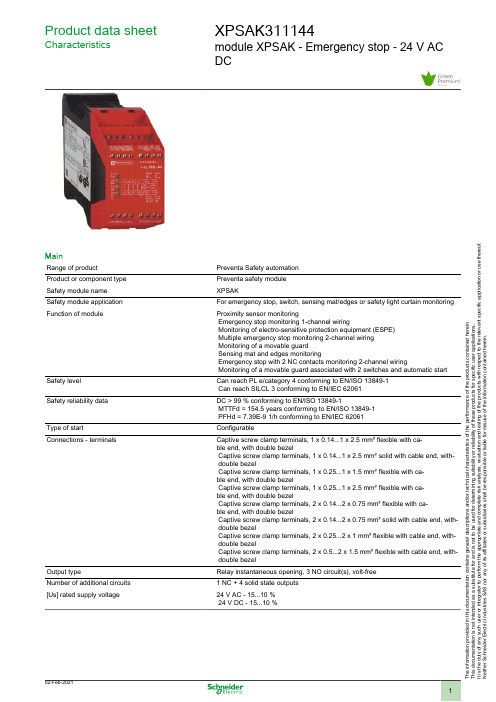
Product data sheetCharacteristicsXPSAK311144module XPSAK - Emergency stop - 24 V AC DCMainRange of productPreventa Safety automation Product or component type Preventa safety module Safety module name XPSAKSafety module application For emergency stop, switch, sensing mat/edges or safety light curtain monitoring Function of moduleProximity sensor monitoringEmergency stop monitoring 1-channel wiringMonitoring of electro-sensitive protection equipment (ESPE) Multiple emergency stop monitoring 2-channel wiring Monitoring of a movable guard Sensing mat and edges monitoringEmergency stop with 2 NC contacts monitoring 2-channel wiringMonitoring of a movable guard associated with 2 switches and automatic start Safety levelCan reach PL e/category 4 conforming to EN/ISO 13849-1 Can reach SILCL 3 conforming to EN/IEC 62061Safety reliability dataDC > 99 % conforming to EN/ISO 13849-1MTTFd = 154.5 years conforming to EN/ISO 13849-1 PFHd = 7.39E-9 1/h conforming to EN/IEC 62061Type of startConfigurableConnections - terminalsCaptive screw clamp terminals, 1 x 0.14...1 x 2.5 mm² flexible with ca-ble end, with double bezelCaptive screw clamp terminals, 1 x 0.14...1 x 2.5 mm² solid with cable end, with- double bezelCaptive screw clamp terminals, 1 x 0.25...1 x 1.5 mm² flexible with ca-ble end, with double bezelCaptive screw clamp terminals, 1 x 0.25...1 x 2.5 mm² flexible with ca-ble end, with double bezelCaptive screw clamp terminals, 2 x 0.14...2 x 0.75 mm² flexible with ca-ble end, with double bezelCaptive screw clamp terminals, 2 x 0.14...2 x 0.75 mm² solid with cable end, with- double bezelCaptive screw clamp terminals, 2 x 0.25...2 x 1 mm² flexible with cable end, with- double bezelCaptive screw clamp terminals, 2 x 0.5...2 x 1.5 mm² flexible with cable end, with- double bezelOutput typeRelay instantaneous opening, 3 NO circuit(s), volt-free Number of additional circuits 1 NC + 4 solid state outputs [Us] rated supply voltage24 V AC - 15...10 % 24 V DC - 15...10 %T h e i n f o r m a t i o n p r o v i d e d i n t h i s d o c u m e n t a t i o n c o n t a i n s g e n e r a l d e s c r i p t i o n s a n d /o r t e c h n i c a l c h a r a c t e r i s t i c s o f t h e p e r f o r m a n c e o f t h e p r o d u c t s c o n t a i n e d h e r e i n .T h i s d o c u m e n t a t i o n i s n o t i n t e n d e d a s a s u b s t i t u t e f o r a n d i s n o t t o b e u s e d f o r d e t e r m i n i n g s u i t a b i l i t y o r r e l i a b i l i t y o f t h e s e p r o d u c t s f o r s p e c i f i c u s e r a p p l i c a t i o n s .I t i s t h e d u t y o f a n y s u c h u s e r o r i n t e g r a t o r t o p e r f o r m t h e a p p r o p r i a t e a n d c o m p l e t e r i s k a n a l y s i s , e v a l u a t i o n a n d t e s t i n g o f t h e p r o d u c t s w i t h r e s p e c t t o t h e r e l e v a n t s p e c i f i c a p p l i c a t i o n o r u s e t h e r e o f .N e i t h e r S c h n e i d e r E l e c t r i c I n d u s t r i e s S A S n o r a n y o f i t s a f f i l i a t e s o r s u b s i d i a r i e s s h a l l b e r e s p o n s i b l e o r l i a b l e f o r m i s u s e o f t h e i n f o r m a t i o n c o n t a i n e d h e r e i n .ComplementarySynchronisation time between inputs Unlimited (manual start)2 or 4 s depending of wiring (automatic start)Supply frequency50/60 HzMaximum power consumption in VA5 VA ACInput protection type Internal, electronic[Uc] control circuit voltage24 V DCMaximum line resistance28 OhmBreaking capacity180 VA holding AC-15 C300 relay output1800 VA inrush AC-15 C300 relay outputBreaking capacity 1.5 A at 24 V (DC-13) time constant: 50 ms for relay outputOutput thermal current 6 A per relay for relay output[Ith] conventional free air thermal current18 AAssociated fuse rating4 A gG or gL for relay output conforming to EN/IEC 60947-5-1, DIN-VDE 0660 part 2006 A fast blow for relay output conforming to EN/IEC 60947-5-1, DIN-VDE 0660 part 200Minimum output current10 MA for relay outputMinimum output voltage17 V for relay outputMaximum response time on input open40 Ms[Ui] rated insulation voltage300 V (pollution degree 2) conforming to IEC 60947-5-1300 V (pollution degree 2) conforming to DIN VDE 0110 part 1[Uimp] rated impulse withstand voltage4 KV overvoltage category III conforming to IEC 60947-5-14 KV overvoltage category III conforming to DIN VDE 0110 part 1Local signalling 4 LEDsCurrent consumption30 mA at 24 V AC on power supplyMounting support35 mm symmetrical DIN railNet weight0.3 KgEnvironmentStandards EN/ISO 13850EN 1088/ISO 14119EN/IEC 60947-5-1EN/IEC 60204-1Product certifications CSAULTÜVIP degree of protection IP20 (terminals) conforming to EN/IEC 60529IP40 (enclosure) conforming to EN/IEC 60529Ambient air temperature for operation-10…55 °CAmbient air temperature for storage-25…85 °CPacking UnitsUnit Type of Package 1PCENumber of Units in Package 11Package 1 Weight354 GPackage 1 Height 6.5 CmPackage 1 width10.5 CmPackage 1 Length12.5 CmOffer SustainabilitySustainable offer status Green Premium productREACh Regulation REACh DeclarationEU RoHS Directive Pro-active compliance (Product out of EU RoHS legal scope)EU RoHS Decla-rationMercury free YesRoHS exemption information YesChina RoHS Regulation China RoHS DeclarationEnvironmental Disclosure Product Environmental ProfileCircularity Profile End Of Life InformationWEEE The product must be disposed on European Union markets following speci-fic waste collection and never end up in rubbish binsPVC free YesContractual warrantyWarranty18 monthsProduct data sheetXPSAK311144Dimensions DrawingsDimensionsProduct Life Status :End of commerc. announcedXPSAK311144 may be replaced by any of the following products:XPSUAK12APPreventa module Cat.4 features XPSUAF + PNP/NPN, safety mat 24vac/dc screwQty 1Reason for Substitution: End of life | Substitution date: 01 Jun 2019 |XPSUAK12APPreventa module Cat.4 features XPSUAF + PNP/NPN, safety mat 24vac/dc screwQty 1Reason for Substitution: End of life | Substitution date: 01 Jun 2019 |XPSUAK12APPreventa module Cat.4 features XPSUAF + PNP/NPN, safety mat 24vac/dc screwQty 1Reason for Substitution: End of life | Substitution date: 01 Jun 2019 |XPSUAK12APPreventa module Cat.4 features XPSUAF + PNP/NPN, safety mat 24vac/dc screwQty 1Reason for Substitution: End of life | Substitution date: 19 Feb 2020 |XPSUAK12APPreventa module Cat.4 features XPSUAF + PNP/NPN, safety mat 24vac/dc screwQty 1Reason for Substitution: End of life | Substitution date: 21 Aug 2020 |。
亚太地区(港澳地区除外)

电子邮件:Service_KR@
中银国际(新加坡)有限公司
BOC INTERNATIONALSINGAPORE) PTE. LTD.
4 BATTERY ROAD #04-00,BANK OFCHINA
BUILDING,SINGAPORE049908
传真:(612) 96872919
欧洲地区
EUROPE
伦敦分行
LONDONBRANCH
90 CANNON STREET,LONDONEC4N6HA,U.K.
SWIFT:BKCH GB 2LA
电传:8812913 BKCHI G
电话:(4420) 72828888
传真:(4420) 76263892
电子邮件:@
电子邮件:Service_SG@
东京分行
TOKYOBRANCH
BOC BLDG.3-4-1AKASAKA,MINATO-KU,
TOKYO,107-0052JAPAN
SWIFT: BKCH JP JT
电传:516002-BKCH UI
电话:(813) 35058818
传真:(6221) 5201113
电子邮件:Service_ID@
墨尔本分行
MELBOURNEBRANCH
270 QUEEN STREET,
MELBOURNEVIC 3000,AUSTRALIA
电话:(613) 96023655
传真:(613) 96023383
巴林代表处
电子邮件:Service_UK@
巴黎分行
PARISBRANCH
23-25 AVENUE DELA GRANDE ARMEE75116
日本食品农产品进口商名录

日本食品农产品进口商名录香港进口商名录日本综合贸易商社ALC。
INC。
地址:东京都中央区新川1-23-5SHINKAWA-EAST,1-23-5,SHINKAWA,CHUO-KU,TOKYO Tel:0081-3-5541-2053 Fax:0081-3-5541-2140E-mail:YOUSIHARA@aicinc.co.jp社长:本村博志资本金:23,000万日元从业人数:175人设立:1979年1月业务内容:食品特色:消费物资输入各国(株)爱峰商会AIHOO TRADINGCO,LTD。
地址:奇玉县大宫市日进町3-493-23-493-2。
NISSHINCHO,OMIRATel:0081-48-668-5055 Fax:0081-48-668-1243社长:荻谷弘康复资本金:1,500万日元老派从业人数:4人设立:1983年6月业务内容:冷冻蔬菜等农业产业加工品特色:中国贸易的多年的业务经验有专业商社(株)葵源六甲AOLGEN-ROKKOCORP地址:京都府京都市南区久世高田町126Tel:0081-75-931-5525 Fax:0081-75-931-5584社长:杉山正义资本金:1000万日元老派从业人数:3人设立:1993年3月业务内容:食品青山贸易(株)http/AOYAMA TRADECO,LTD地址:兵车县姬路市青山14641464,AOYAMA,HIMEJI,HYOGOTel:0081-792-66-6035 Fax:0081-792-67—4624 E-mail:aoyamaz@siluer.ocn.ne.jp社长:赵善云资本金:1000万日元从业人数:15人设立:1992年10月业务内容:化学品(株)本铺AKACHAN HONPOCO,LTD地址:大阪府大阪市中央区南本町3-3-213-3-21 MINAMI-HONMACHI,CHUO-KU,OSAKATel:0081-6-6251-0625 Fax:0081-6-6251-3340社长:小原正司资本金:19000万日元从业人数:2700人设立:1941年2月业务内容:进口生活用品及生产资料朝阳贸易(株)ASAHI TRADINGCO,LTD地址:东京都中央区八丁堀4-10-4 白铜第一HKUDODALLTLBLDG,4-10-4,HATTYOBORL,CHUO-KU,TOKYO Tel:0081-3-3351-0771 Fax:0081-3-3351-2344社长:华井满资本金:9600万日元从业人数:50人设立:1968年9月业务内容:原料羽毛,进出口食品原料及健康食品(株)亚细亚交易AJAKOEKICO,LTD地址:大分县别府市原町18-2418-24,HARA-MACHI,BEPPU,OITATel:0081-977-21-0888 Fax:0081-977-21-2048 E-mail:tukasaki@mocha.ocn.ne.jp社长:圜田展久资本金:2000万日元从业人数:3人设立:1972年5月业务内容:进口竹制品制药(株)ASGENPHARMACEUTICAL CO,LTDhttp/www.asgen.cojp地址:爱知县名古屋市东区泉2-28-22-28-2,IZUML,HLGASHI-KU,NAGOYATel:0081-52-9031-1212 Fax:0081-52-931-1331E-mail:asgen@asgen.co.jp社长:水墅昌树资本金:1000万日元从业人数:60人设立:1968年1月业务内容:中药材,中成药,化工医药品,食品原料(株)甘栗太郎AMAGURITARO CO,LTD地址:东京都千代田区神田松永町1111,MATSUNAGACHO,KANDA,CHIYODA-KU,TOKYO Tel:0081-3-3251-9021 Fax:0081-3-3251-9280社长:田中康则资本金:1280万日元从业人数:130人设立:1956年11月业务内容:天津甘栗(株)新井清太郎商店SEITARO ARAICO,LTD地址:神奈川县横浜市中区尾上町1-81-8,ONOE-CHO-NAKA-KU,YOKOHANATel:0081-45-681-6729 Fax:0081-45-662-2357社长:新井光世资本金:2000万日元从业人数:100人设立:1888年4月业务内容:香辛料,辣椒干,脱水蔬菜,植物生产品,柳腾制品,轻工品。
著名室内设计案例赏析PPT课件

1.童趣盎然——Neopolis设计缤纷儿童房 2.色彩鲜艳的概念小公寓设计
目 录
三、个性独特的简约设计
1. 拥有超长窗帘的住宅 2. Suppose Design 简约美丽的花园住宅 3.奥迪Festkogl Alm旗舰店 4.南京会所-小东园
2020傅/3/1琬9 芸2015085313 环三
头保持着一定的关联性。奥迪标志的圆环造型让整个平台的立面显得更为
突出。用于汽车制造的轻量化材料如今也应用到建筑和室内设计上,赋予
了这个项目一种新的样貌——前沿、未来。这种设计的影响了是巨大的,
那些哑光表层的阳极氧化铝材作为背板,热烈地迎接宾客的到来。
2020/3/19
67
2020/3/19
68
·Bladerunner品牌的一些反光强烈的未来感家具也给这里增添了不一样 的感觉。在Festkogl Alm,最新的关爱设计辐射到了这里的方方面面。 ·建筑反向支持着周边的环境,而且设计也兼容了传统的元素,例如木质 的面板和梁柱,这与金属产生出明显的差异,确保了从度假区向外看去并 不那么得引人注目,但同时又有些亮点,让人感到些许不同之处。 ·大胆的图形和棱角分明的线条会让人通常与城市环境联想到一起,这种 朴素的设计迸发出令人意想不到的结果,看似新鲜是因为这里提供了一种 新的透视感。当看到这种带有浓重传统特色的现代设计的时候,那些以供 取暖的火炉、惹人多看一眼的传统棚屋室内元素,都会强迫你摒弃先前的 观点,融入这种让人感到意外的设计风貌。 ·置入的高输出LED灯在室内散发出暖色调的光,进一步突出新旧照明系 统之间的差异,重新诠释着迎宾的热情。
这是住宅的客厅下半部分没有墙和玻璃窗来对外界进行隔断而是采用了开敞空间的这是住宅的客厅下半部分没有墙和玻璃窗来对外界进行隔断而是采用了开敞空间的类型把客厅和自然紧密结合而客厅上半部分运用玻璃窗具有很好的采光性能
Dorna Technology EPS-B1 Series Full Digital AC Ser

EPS-B1 seriesFull Digital AC Servo Driver System From top technology • Serve the FA industryDorna Technology Co., Ltd DORNA Technology Co., LtdAddress : No 99, Zhuangchi Middle Rd, Ganyao Industrial Park ,Jiashan Zhejiang, ChinaTel: +86-0573-********Fax: +86-0573-********E-mail:********************Web site: Company ProfileDorna Technology Co., Ltd. is located at Jiashan County of Zhejiang Province, about 1 hour from Shanghai and Hangzhou by car. The first phase of production base covers an area of more than 50mu, with complete and sound production, research & development and sales. The registered capital of the Company is RMB 50 million. With more than 300 employees, the Company now has a highly-educated top-caliber management and R&D team. We are an innovative high technology enterprise with independent intellectual property rights and we are specialized in the research & development, production, sales and service of servo motor, servo driver, CNC devices, electrical pitch control system of wind turbine generator and various types of automatic equipment. We value technological innovation and have been granted with a dozen of national patents. Our core technological product—AC Servo System—is now leading the industry in domestic market, characterized in excellent performance and high reliability, widely used for CNC machine tools, textile & knitwear machineries, packaging, printing, food-making and pharmaceutical equipment, carving machinery, spring machinery, plastic machinery, papermaking and metallurgy, mechanical arm, robot and other CNC manufacturing, teaching apparatus & experimental devices, as well as industrial mechanical automation and other relevant fields. Our products can completely replace similar products imported from overseas brands.Sticking to the operational concept of “business in good faith" and the principle of “combination of technological achievements and client's needs”, the Company highlights "product research & development and marketing", and implements the strictest production process and quality testing.The enterprising team of the Company is committed to climbing one peak of high technology after another. The Company has increased investment in technological research and development in the hope of creating a series of items and products that can take the leading position in the industry. Our products are CE-certified and have been included in the “Major and Key Technological Projects of Zhejiang Province” and the “Projects Supported by National Innovation Fund”, and won titles such as “Scientific & Technological Progress Award of Jiaxing City”. The Company is now ISO9001 certified and has been rated as "software enterprise”, “small and middle-sized technological enterprise", and “national high-tech enterprise”.Looking forward, with “building a world-famous FA enterprise" as our mission, Dorna Technology will make persistent efforts to create more innovations in order to provide greater development space and opportunity for employees and offer better products and services for clients. At the same time, with our size and business growing quickly, we now sincerely invite talents from all sources to join us for building the national industry together, transcending ourselves in the broad stage of career, and making our dream come true!The following content is for reference only and subject to change without notification. Please contact with our after-sale service department.Dorna Technology ParkOrdinary servo 500K EPS-B1 series 4MFastEPS-B1 seriesProduct characteristicsResponse frequency 1KHz3 times overloadGrade 2 Notch Filter3 times rated torque Rated rotating speed (rpm)Vibrates No filter Filter setup completedVibration decreases R a t e d t o r q u e (N •M )Input and output pulse frequency 4MbpsRealize speed response frequency 1KHz (200W experimental model) Up-to-date chip is adopted to improve computing speed; algorithm is controlled through the newly developed speed loop and current loop to improve the servo system’s response control performance.Torque 3 times overloadEPS-B1 series of Servo driver has the capacity for 3 times overload, which improves the servo’s responsiveness.Grade-2 notch filter settableGrade-2 notch filter that can reduce phase lag is used to restrain resonance of mechanical system and improve equipment’s speed response.Pulse instruction and feedback realize 4MbpsIn order to respond to top high resolution instruction (pulse form) in the industry, EPS-B1 series servo driver‘s instruction input and feedback have achieved 4Mbps. High resolution pulse receipt can be realized under half-closed loop and fully-closed loop.PrecisenessEPS-B1 seriesProduct characteristicsHigh resolutionShortened positioning timeRestrained external interferenceQuick instruction trackingLow cogging torquePosition deviationPosition designating Setting time<3msPosition ending signalTorqueInterference detection is OFF Interference detection is ONPosition instructionPosition deviationSpeed SpeedTorqueSupport up to 17 bit absolute value encoder It can carry 17 bit (131,072 lines) absolute value encoder to improve positioning accuracy and low-speed operation stability. It can implement control suitable for high resolution encoder.Position setting time shortened!Position setting time of the device can be greatly reduced by using the new algorithm.Able to restrain external interference Effect from external interference can be restrained effectively by expanding the new interference observation function of suitable frequency.Quick position and speed instruction tracking As the new position and speed controller is adopted, position control tracking is greatly improved, and position deviation is achieved to be ≒0.The motor has low cogging torque to realize stable operation By using the new magnetic field analysis design and motor processing technology, the motor’s torque pulsation is reduced, thus to improve speed stability and reduce servo system’s torque pulsation.H i g h r e s o l u t i on a b s o l u t e 17b i t (R e s o l u t i o n 131,072)Previous products New motor seriesCogging torque reduced by more than 2 timesOthers EPS-B1 seriesProduct characteristicsEPS-B1 series is built-in regenerative resistor (optional part) that can absorb regenerated electricity when motor isdecelerating. When the built-in regenerative resistor is not capable enough, external regenerative resistor can be used.It has built-in dynamic brake for emergency braking. Through parameter setting, many action modes of motor shutdown can be chosen for cases of servo OFF, forward/backward drive inhibition, power cutoff, and stop due to failure.Responsiveness is improved to reduce effect of mechanical friction. According to deviation load compensation and actiondirection at the time of compensatory operation, 2 types of friction compensation can be set for dynamic frictioncompensation that changes direction.Password settingThere are many gain switch-over modes inside. Different gains can be set at stoppage and operation to improve thesystem’s responsiveness.When speed control (zero clamping) is used, as analog instruction may lead to drifting, the servo can be locked up by using this function to make it stop running.It can prevent user parameter from being modified inadvertently.The servo driver automatically judges the servo motor's power and specification (only applicable to communication typeencoder), no need to set motor parameters; when connection is not applicable to motor, relevant warning will be given.In order to reduce higher harmonic, it is equipped with the terminal to connect DC reactor.Setting or monitoring can be implemented at the site conveniently. Built-in keyboard can be used to change parameters,monitor and adjust alarm tracking.A A 0D40 400W0D75 750W 0001 1.0KW 01D5 1.5KW EPS B1A 0D75130DN MA 1C A M K 0001Without brake With brakeWith key slot Without oil seal Without key slot With oil seal With key slot With oil seal Without key slot Without oil seal60801300D400D750D8500011C DK KYMN A B IJ 2000300001D201D5400W 1.0KW 1.2KW 1.5KW 750W 850W Line-saving gain 5000ppr 17 bit serial (gain)17 bit serial (absolute value)Factory code MAHAMBHB Servo SystemModel identificationServo driverServo motorProduct name Product series B1Factory codeServo driver capacityPedestal numberInertia voltage classRated powerRated speed (rmp)Encoder type Brake selection Key slot oil seal selection Design series Product name Power voltage specification Hardware versionSpecification Symbol Specification Symbol SpecificationSymbolSpecification Symbol Specification Symbol Specification Symbol Specification SymbolSpecification Symbol Specification Symbol Specification SymbolSpecification Symbol Specification Medium/low inertia 220V High inertia 220V Medium/low inertia 380V High inertia 380V 60 flange 80 flange 130 flange SpecificationSymbol SymbolSpecificationSymbolSingle phase/threephases 220VIt turns on when the main loop power is ON. When the main loop power is OFF, if thedriver has residual voltage inside, theindicator will still be on. Don’t touch theterminal when the light is on, lest electricshock may happen.DC reactor connection terminalTerminal for connecting DC reactor used torestrain power supply’s higher harmonic Servo motor power terminalConnected with motor ’s power joint (U,V and W)▲ AC220V series: For connecting AC220Vpower of driver motor▲ AC380V series: For connecting AC380Vpower of driver motor Control loop power terminal▲ AC220V series: For supplying AC220Vpower for internal power of driver▲ AC380V series: For supplying AC380V power for internal power of driver Motor encoder port It connects coder signal at the servo motor side IO signal portConnected with upper controller,it is the port for instruction inputsignal or sequential controlinput/output munication interface ▲ Support RS485 and CAN bus;▲ One-in and one-out design facilitatesserial connection among manymachinesEarth connection terminal It connects the input power earth wire and motor's earth wire. It is a terminal for preventing electric shock. This terminal must be connected.EPS-B1 series servo driverConfiguration and interfaceInput voltagePower indicator lightMain loop power terminalInternal/external brake resistor terminal▲ Internal brake resistor is used: P and D are short-connected;▲ External brake resistor is used: P and D are disconnected and P and C are end-connected to external brake resistors ▲ External brake unit is used: P and D are disconnected; and P and C are disconnected; P is connected to external brake unit;Display operation area ▲ Display area: Servo state is displayed by 5-digit 7-segment LED ▲ Operation area: Man-machine interaction is realized by 4-digitkeyingServo driverThree-phaseLow speed position instruction Please handle shield wire stubs properlyExternal brake resistancePower sectionBrakeEncoderHigh speed position instructionIt indicates multi-strand twisted wireServo function ON (servo-on when on)Control mode switch (control mode switch)Positive limitation (positive direction operation limited)Negative limitation (negative direction operation limited)Reset signal input (clean position deviation when ON)Alarm clearance (alarm clearance when ON)Pulse input inhibited (no pulse input received when ON)Zero-speed restoration (zero-speed restoration when ON)1. DC24V shall be prepared by user. DC24V power supply shall use double insulation.Shield wire connected to connector enclosure Note: optical coupler output Maximum use voltage DC30VMaximum use current DC50mA Alarm output OFF when giving alarmA pulse differential output outputoutputB pulse differential outputZ pulse differential output Encoder feedback signal output Connector enclosure EPS-B1 series servo driverStandard wiringEPS-B1 series servo driverSpecificationBasic specificationThree-phases AC220V +10~-15%, 50/60Hz Single-phase or three-phases full wave rectification IGBT PWM control, sine-wave current driveLine-saving gain encoder:5000ppr (1/20000 resolution, gain);Serial coder:17bit (gain/absolute value)Use ambient temperature: 0~+55℃; Storage temperature: -20~85℃Below 90%RH (icing and dewing not allowed)Protection class: IP10, Cleanness: 2But it should be:● With no corrosive gas and combustible gas● With no water, oil or drug splashing● An environment with little dust, ash, salt and metallic powderBelow 1000mCEPedestal installation type1: 50000 ~ 100% load: Below ±0.01 (rated speed)Rated voltage ± 10%: 0.001% (at rated speed)25 ± 25℃: below ±0.1% (at rated speed)± 3%0 ~ 10s (acceleration and deceleration may be set respectivelyPhase A, phase B, and phase Z: Linear drive output Frequency-divided pulses: Line-saving gain coder may set it freely 17bit serial coder is 16 ~ 16384;Servo connection input (S-ON), control mode switch-over input (control mode switch-over input), positive drive inhi--bition input (POT), negative drive inhibition input (NOT), deviation counter clear input (CLR), alarm clear (A-RST), gain switch-over input (GAIN), instruction pulse inhibition input (INH), etc. Assignment of the above-mentioned signals and positive/negative logic change can be achieved.Alarm signal (ALM), positioning completion signal (COIN), Z pulse collector signal (CZ), external brake lifting signal (BK), servo ready (S-RDY), etc. Assignment of the signals mentioned as above and positive / negative logic change can be achieved.In case of use relay, maximum is N=31 stations Through parameter setting Computer and upper machine In case of use relay, maximum is N=127 stations Through parameter setting Upper machine7 segments of LED * 5 digits, 4 keysAct when main loop power is OFF, servo is alarming, servo is off,and in case of over travel (OT)In case of POT or NOT input action, dynamic brake (DB) stops,deceleration stops, or free operation stopsOver-current, over-voltage, under-voltage, over-load, regeneration fault, etc. Built-in regenerative resistor or external regenerative resistor1 point. Alarm signal;3 pointsControl method Feedback Use ambient temperature / Storage temperature Ambient humidity / Storage humidity Anti-vibration / Anti-impact strength Protection class / cleanness Elevation Applicable standard Structure Speed fluctuation rate Performance Coder frequency-divided pulse outputInput/output signal Sequential control input signal Sequential control output signal RS485 comm.1:N comm.Axis address settingConnecting equipment1:N comm.Axis address settingConnecting equipment Display keying function Dynamic brake (DB)Regenerative processing Over-travel prevention Protection functionCANopen munication function Assignable input signal Number o f p oints Number o f p oints Number o f p oints Function Function 8 points Non-assignable input signal Assignable input signal Load fluctuation V oltage fluctuation Temperature fluctuation Torque control precision (reproducibility)Soft start time setting Speed control range Use condition Input power 220V class1.273.82 4.112.550000.880.450.250.139Servo motorEPS-B1 drive (B type case) dimensions SpecificationParameter table of 60/80 series servo motorParameter table of 130 series servo motorEPS-B1 drive (A type case) dimensions Working regime: S1 continuous Vibration: 5G Insulation resistance: DC500V , above 10MΩOperational temperature: 0 ~ 40℃ (no freezing)Altitude: Below altitude 1000m V oltageMotor modelPedestal No.V oltageMotor modelPedestal No.Rated outputRated torqueInstantaneous max. torqueRated currentInstantaneous max. currentRated speedMax. speedTorque constantRotational inertiaRated outputRated torqueInstantaneous max. torqueRated currentInstantaneous max. currentRated speedMax. speedTorque constantRotational inertia Heat resistance class: B Insulation resistance: AC1500V , 1 minute Installation mode: Flange type Operational humidity: 20% ~ 80% (no dewing) Way of protection: Fully closed and self cooled IP65(except the part that the shaft goes through)-10-105125DimensionsInstallation dimensions of 60/80 series motor unit : mmInstallation dimensions of 130 series motor unit : mmModel Flange face dimensions Shaft end dimensionsModel Note: Information contained in this manual is general description or introduction to characteristics, not always consistent with the fact in actual application, or possibly not fully applicable due to further development of product.Flange face dimensionsShaft end dimensions。