射线无损检测缺陷图谱集 06
常见缺陷射线图谱大全,NDT互联网联盟倾情奉献!内下载链接!

常见缺陷射线图谱⼤全,NDT互联⽹联盟倾情奉献!内下载链接!本图谱根据缺陷性质共分6个章节:1. 裂纹Cracks2. 未焊透Lack of Penetration3. 未熔合Incomplete Fusion4. 条状缺陷Linear indication5. 圆形缺陷Rounded indication6. 伪缺陷Image Artifacts1. 裂纹Cracks定义:裂纹是指材料局部断裂形成的缺陷。
影像特征:底⽚上裂纹和典型影像是轮廓分明的⿊线或⿊丝。
其细节特征包括:⿊线或⿊丝上有微⼩的锯齿,有分叉,粗细和⿊度有时有变化,有些裂纹影像呈较粗的⿊线与较细的⿊丝相互缠绕状;线的端部尖细,端头前⽅有时有丝状阴影延伸。
2. 未焊透Lack of Penetration定义:未焊透是指母材⾦属之间没有熔化,焊缝⾦属没有进⼊接头的根部造成的缺陷。
影像特征:未焊透的典型影像是细直黒线,两侧轮廓都很整齐,为坡⼝钝边痕迹,宽度恰好为钝边的间隙宽度。
有时坡⼝钝边有部分溶化,影像轮廓就变得不很整齐,线宽度和⿊度局部发⽣变化,但只要能判断是处于焊缝根部的线性缺陷,仍判定为未焊透。
未焊透有底⽚上处于焊缝根部的投影位置,⼀般在焊缝中部,因透照偏、焊偏等原因也可能偏向⼀侧。
未焊透呈断续或连续分布,有时能贯穿整张底⽚。
3. 未熔合Incomplete Fusion定义:未熔合是指焊缝⾦属与母材⾦属可焊缝⾦属之间未熔化结合在⼀起的缺陷。
影像特征:根部未熔合的典型影像是连续或断续的⿊线,线的⼀侧轮廓整齐且⿊度较⼤,为坡⼝或钝边的痕迹,另⼀侧轮廓可能较规则,也可能不规则。
根部未熔合在底⽚上的位置就是焊缝根部的投影位置,⼀般在焊缝的中间,因坡⼝形状或投影⾓度等原因出可能偏向⼀边。
坡⼝未熔合的典型影像是连续或断续的⿊线,宽度不⼀,⿊度不均匀,⼀侧轮廓较齐,⿊度较⼤,另⼀侧轮廓不规则,⿊度较⼩,在底⽚上的位置⼀般在中⼼⾄边缘的1/2处,沿焊缝纵向延伸。
无损检测rt缺陷图谱续集 04

板对接焊缝射线气孔、未焊透、夹渣缺陷图谱Rt缺陷图片061
板对接焊缝射线气孔缺陷图谱
Rt缺陷图片062
Rt缺陷图片063
板对接焊缝射线链状气孔缺陷图谱Rt缺陷图片064
Rt缺陷图片065
板对接焊缝射线气孔缺陷图谱Rt缺陷图片066
Rt缺陷图片067
板对接焊缝射线密集气孔缺陷图谱Rt缺陷图片068
板对接焊缝射线密集气孔缺陷图谱Rt缺陷图片069
板对接焊缝射线链状气孔缺陷图谱Rt缺陷图片070
Rt缺陷图片071
板对接焊缝射线气孔缺陷图谱Rt缺陷图片072
Rt缺陷图片073
板对接焊缝射线密集气孔缺陷图谱Rt缺陷图片074
板对接焊缝射线密集气孔缺陷图谱Rt缺陷图片075
板对接焊缝射线密集气孔缺陷图谱Rt缺陷图片076
Rt缺陷图片077
板对接焊缝射线烧穿缺陷图谱Rt缺陷图片078
Rt缺陷图片079
板对接焊缝射线气孔缺陷图谱Rt缺陷图片080。
无损检测射线常见缺陷图集及分析63页PPT

25、学习是劳动,是充满思想的劳动。——乌申斯基
谢谢!
无损检测射线常见缺陷图集分析
51、山气日夕佳,飞鸟相与还。 52、木欣欣以向荣,泉涓涓而始流。
53、富贵非吾愿,帝乡不可期。 54、雄发指危冠,猛气冲长缨。 55、土地平旷,屋舍俨然,有良田美 池桑竹 之属, 阡陌交 通,鸡 犬相闻 。
21、要知道对好事的称颂过于夸大,也会招来人们的反感轻蔑和嫉妒。——培根 22、业精于勤,荒于嬉;行成于思,毁于随。——韩愈
射线检测常见缺陷图
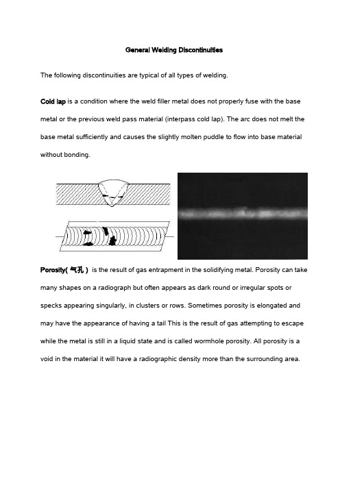
General Welding DiscontinuitiesThe following discontinuities are typical of all types of welding.Cold lap is a condition where the weld filler metal does not properly fuse with the base metal or the previous weld pass material (interpass cold lap). The arc does not melt the base metal sufficiently and causes the slightly molten puddle to flow into base material without bonding.Porosity(气孔)is the result of gas entrapment in the solidifying metal. Porosity can take many shapes on a radiograph but often appears as dark round or irregular spots or specks appearing singularly, in clusters or rows. Sometimes porosity is elongated and may have the appearance of having a tail This is the result of gas attempting to escape while the metal is still in a liquid state and is called wormhole porosity. All porosity is a void in the material it will have a radiographic density more than the surrounding area.Cluster porosity(密集气孔)is caused when flux coated electrodes are contaminated with moisture. The moisture turns into gases when heated and becomes trapped in the weld during the welding process. Cluster porosity appear just like regular porosity in the radiograph but the indications will be grouped close together.Slag inclusions(夹渣)are nonmetallic solid material entrapped in weld metal or between weld and base metal. In a radiograph, dark, jagged asymmetrical shapes within the weld or along the weld joint areas are indicative of slag inclusions.Incomplete penetration (IP) or lack of penetration (LOP)(未焊透)occurs when the weld metal fails to penetrate the joint. It is one of the most objectionable weld discontinuities. Lack of penetration allows a natural stress riser from which a crack may propagate. The appearance on a radiograph is a dark area with well-defined, straight edges that follows the land or root face down the center of the weldment.Incomplete fusion(未融合)is a condition where the weld filler metal does not properly fuse with the base metal. Appearance on radiograph: usually appears as a dark line or lines oriented in the direction of the weld seam along the weld preparation or joining area.Internal concavity or suck back(内凹)is condition where the weld metal has contracted as it cools and has been drawn up into the root of the weld. On a radiograph it looks similar to lack of penetration but the line has irregular edges and it is often quite wide in the center of the weld image.Internal or root undercut(根部咬边)is an erosion of the base metal next to the root of the weld. In the radiographic image it appears as a dark irregular line offset from the centerline of the weldment. Undercutting is not as straight edged as LOP because it does not follow a ground edge.External or crown undercut(外咬边)is an erosion of the base metal next to the crown of the weld. In the radiograph, it appears as a dark irregular line along the outside edge of the weld area.Offset or mismatch(错边)are terms associated with a condition where two pieces being welded together are not properly aligned. The radiographic image is a noticeable difference in density between the two pieces. The difference in density is caused by the difference in material thickness. The dark, straight line is caused by failure of the weld metal to fuse with the land area.Inadequate weld reinforcement(未焊满)is an area of a weld where the thickness of weld metal deposited is less than the thickness of the base material. It is very easy to determine by radiograph if the weld has inadequate reinforcement, because the image density in the area of suspected inadequacy will be more (darker) than the image density of the surrounding base material.Excess weld reinforcement(焊缝余高过高)is an area of a weld that has weld metal added in excess of that specified by engineering drawings and codes. The appearance on a radiograph is a localized, lighter area in the weld. A visual inspection will easily determine if the weld reinforcement is in excess of that specified by the engineering requirements.Cracks(裂纹)can be detected in a radiograph only when they are propagating in a direction that produces a change in thickness that is parallel to the x-ray beam. Cracks will appear as jagged and often very faint irregular lines. Cracks can sometimes appear as "tails" on inclusions or porosity.Discontinuities in TIG weldsThe following discontinuities are peculiar to the TIG welding process. These discontinuities occur in most metals welded by the process including aluminum andstainless steels. The TIG method of welding produces a clean homogeneous weld which when radiographed is easily interpreted.Tungsten inclusions(夹钨). Tungsten is a brittle and inherently dense material used in the electrode in tungsten inert gas welding. If improper welding procedures are used, tungsten may be entrapped in the weld. Radiographically, tungsten is more dense than aluminum or steel; therefore, it shows as a lighter area with a distinct outline on the radiograph.Oxide inclusions are usually visible on the surface of material being welded (especially aluminum). Oxide inclusions are less dense than the surrounding materials and, therefore, appear as dark irregularly shaped discontinuities in the radiograph.Discontinuities in Gas Metal Arc Welds (GMAW)The following discontinuities are most commonly found in GMAW welds.Whiskers are short lengths of weld electrode wire, visible on the top or bottom surface of the weld or contained within the weld. On a radiograph they appear as light, "wire like" indications.Burn-Through(烧穿)results when too much heat causes excessive weld metal to penetrate the weld zone. Often lumps of metal sag through the weld creating a thick globular condition on the back of the weld. These globs of metal are referred to as icicles. On a radiograph, burn through appears as dark spots, which are often surrounded by light globular areas (icicles).Radiograph Interpretation – Castings(铸件)The major objective of radiographic testing of castings is the disclosure of defects that adversely affect the strength of the product. Casting are a product form that often receive radiographic inspection since many of the defects produced by the casting process are volumetric in nature and, thus, relatively easy to detect with this method. These discontinuities of course, are related to casting process deficiencies, which, if properly understood, can lead to accurate accept-reject decisions as well as to suitable corrective measures. Since different types and sizes of defects have different effects of the performance of the casting, it is important that the radiographer is able to identify the type and size of the defects. ASTM E155, Standard for Radiographs of castings has been produced to help the radiographer make a better assessment of the defects found components. The castings used to produce the standard radiographs have been destructively analyzed to confirm the size and type of discontinuities present. The following is a brief description of the most common discontinuity types included in existing reference radiograph documents (in graded types or as single illustrations).RADIOGRAPHIC INDICATIONS FOR CASTINGSGas porosity or blow holes are caused by accumulated gas or air which is trapped by the metal. These discontinuities are usually smooth-walled rounded cavities of a spherical, elongated or flattened shape. If the sprue is not high enough to provide the necessary heat transfer needed to force the gas or air out of the mold, the gas or air will be trapped as the molten metal begins to solidify. Blows can also be caused by sand that is too fine, too wet, or by sand that has a low permeability so that gas can't escape. Too high a moisture content in the sand makes it difficult to carry the excessive volumes of water vapor away from the casting. Another cause of blows can be attributed to using green ladles, rusty or damp chills andchaplets.Sand inclusions and dross are nonmetallic oxides, appearing on the radiograph as irregular, dark blotches. These come from disintegrated portions of mold or core walls and/or from oxides (formed in the melt) which have not been skimmed off prior to introduction of the metal into the mold gates. Careful control of the melt, proper holding time in the ladle and skimming of the melt during pouring will minimize or obviate this source of trouble.Shrinkage is a form of discontinuity that appears as dark spots on the radiograph. Shrinkage assumes various forms but in all cases it occurs because molten metal shrinks as it solidifies, in all portions of the final casting. Shrinkage is avoided by making sure that the volume of the casting is adequately fed by risers which sacrificially retain the shrinkage. Shrinkage can be recognized in a number of characteristic by varying appearances on radiographs. There are at least four types: (1) cavity; (2) dendritic; (3) filamentary; and (4) sponge types. Some documents designate these types by numbers, without actual names, to avoid possiblemisunderstanding.Cavity shrinkage appears as areas with distinct jagged boundaries. It may be produced when metal solidifiesbetween two original streams of melt, coming from opposite directions to join a common front; cavity shrinkage usually occurs at a time when the melt has almost reached solidification temperature and there is no source of supplementary liquid to feed possible cavities.Dendritic shrinkage is a distribution of very fine lines or small elongated cavities that mayvary in density and are usually unconnected.Filamentary shrinkage usually occurs as a continuous structure of connected lines orbranches of variable length, width and density, or occasionally as a network.Sponge shrinkage shows itself as areas of lacy texture with diffuse outlines, generallytoward the mid-thickness of heavier casting sections. Sponge shrinkage may bedendritic or filamentary shrinkage; filamentary sponge shrinkage appears more blurredbecause it is projected through the relatively thick coating between the discontinuities and the film surface.Cracks are thin (straight or jagged) linearly disposed discontinuities that occur after the melt has solidified. They generally appear singly and originate at casting surfaces.Cold shuts generally appear on or near a surface of cast metal as a result of two streams of liquid meeting and failing to unite. They may appear on a radiograph as cracks or seams with smooth or rounded edges.Inclusions are nonmetallic materials in a supposedly solid metallic matrix. They may be less or more dense than the matrix alloy and will appear on the radiograph, respectively, as darker or lighter indications. The lattertype is more common in light metal castings.Core shift shows itself as a variation in section thickness, usually on radiographic views representing diametrically opposite portions of cylindrical casting portions.Hot tears are linearly disposed indications that represent fractures formed in a metal during solidification because of hindered contraction. The latter may occur due to overly hard (completely unyielding) mold or core walls. The effect of hot tears, as a stress concentration, is similar to that of an ordinary crack; how tears are usually systematicflaws. If flaws are identified as hot tears in larger runs of a casting type, they may call for explicit improvements in technique.Misruns appear on the radiograph as prominent dense areas of variable dimensions with a definite smooth outline. They are mostly random in occurrence and not readily eliminated by specific remedial actions in the process.Mottling is a radiographic indication that appears as an indistinct area of more or less dense images. The condition is a diffraction effect that occurs on relatively vague,thin-section radiographs, most often with austenitic stainless steel. Mottling is caused by interaction of the object's grain boundary material with low-energy X-rays (300 kV or lower). Inexperienced interpreters may incorrectly consider mottling as indications of unacceptable casting flaws. Even experienced interpreters often have to check the condition by re-radiography from slightly different source-film angles. Shifts in mottling are then very pronounced, while true casting discontinuities change only slightly in appearance.Radiographic Indications for Casting Repair WeldsMost common alloy castings require welding either in upgrading from defective conditions or in joining to other system parts. It is mainly for reasons of casting repair that these descriptions of the more common weld defects are provided here. The terms appear as indication types in ASTM E390. For additional information, see theNondestructive Testing Handbook, Volume 3, Section 9 on the "Radiographic Control of Welds."Slag is nonmetallic solid material entrapped in weld metal or between weld material and base metal. Radiographically, slag may appear in various shapes, from long narrow indications to short wide indications, and in various densities, from gray to very dark. Porosity is a series of rounded gas pockets or voids in the weld metal, and is generally cylindrical or elliptical in shape.Undercut is a groove melted in the base metal at the edge of a weld and left unfilled by weld metal. It represents a stress concentration that often must be corrected, and appears as a dark indication at the toe of a weld.Incomplete penetration, as the name implies, is a lack of weld penetration through the thickness of the joint (or penetration which is less than specified). It is located at the center of a weld and is a wide, linear indication.Incomplete fusion is lack of complete fusion of some portions of the metal in a weld joint with adjacent metal; either base or previously deposited weld metal. On a radiograph, this appears as a long, sharp linear indication, occurring at the centerline of the weld joint or at the fusion line.Melt-through is a convex or concave irregularity (on the surface of backing ring, strip, fused root or adjacent base metal) resulting from complete melting of a localized regionbut without development of a void or open hole. On a radiograph, melt-through generally appears as a round or elliptical indication.Burn-through is a void or open hole into a backing ring, strip, fused root or adjacent base metal.Arc strike is an indication from a localized heat-affected zone or a change in surface contour of a finished weld or adjacent base metal. Arc strikes are caused by the heat generated when electrical energy passes between surfaces of the finished weld or base metal and the current source.Weld spatter occurs in arc or gas welding as metal particles which are expelled during welding and which do not form part of the actual weld: weld spatter appears as many small, light cylindrical indications on a radiograph.Tungsten inclusion is usually denser than base-metal particles. Tungsten inclusions appear most linear, very light radiographic images; accept/reject decisions for this defect are generally based on the slag criteria.Oxidation is the condition of a surface which is heated during welding, resulting in oxide formation on the surface, due to partial or complete lack of purge of the weld atmosphere. Also called sugaring.Root edge condition shows the penetration of weld metal into the backing ring or into the clearance between backing ring or strip and the base metal. It appears in radiographs as asharply defined film density transition.Root undercut appears as an intermittent orcontinuous groove in the internal surface of the base metal, backing ring or strip along the edge of the weld root.Real-time RadiographyReal-time radiography (RTR), or real-time radioscopy, is a nondestructive test (NDT) method whereby an image is produced electronically rather than on film so that very little lag time occurs between the item being exposed to radiation and the resulting image. In most instances, the electronic image that is viewed, results from the radiation passing through the object being inspected and interacting with a screen of material that fluoresces or gives off light when the interaction occurs. The fluorescent elements of the screen form the image much as the grains of silver form the image in film radiography. The image formed is a "positive image" since brighter areas on the image indicate where higher levels of transmitted radiation reached the screen. This image is the opposite of the negative image produced in film radiography. In other words, with RTR, the lighter, brighter areas represent thinner sections or less dense sections of the test object.Real-time radiography is a well-established method of NDT having applications in automotive, aerospace, pressure vessel, electronic, and munition industries, among others. The use of RTR is increasing due to a reduction in the cost of the equipment and resolution of issues such as the protecting and storing digital images. Since RTR is being used increasingly more, these educational materials were developed by the North Central Collaboration for NDT Education (NCCE) to introduce RTR to NDT technician students.Real-time Radiography: An Introductory Course Module for NDT StudentsDownload PDF File。
06-射线检测原理

在单位时间内衰变的原子核数量,称为放射 性活度,以α 表示,单位为居里(Ci) 某种物质每秒钟有 3.7×10¹⁰ 个原子衰变,则 该物质的放射性活度为1Ci(居里) 单位质量放射性物质的活度称为比活度,单 位为Ci/g(居里/克)
γ 射线的强度可由测量仪器引起的电离程度 来决定,单位是R(伦琴) 1R 辐射强度,等于在 0℃及 105Pa 压力下,在 1cm3 空气中电离引起离子绝对值总和为一个绝 对静电单位。
3 射线检测
3-1 射线检测原理
射线透过被检物体时,有缺陷部位与无缺陷 部位对射线上的吸收能力不同
射线源
ห้องสมุดไป่ตู้
工件 暗合
缺陷 增感屏 胶片
缺陷影象 底片
以金属材料为例,缺陷部位 ( 气孔或非金属夹 杂物)对射线的吸收能力低于金属基体。
透过缺陷部位的射线强度高于无缺陷部位,根 据透过工件后射线强度的差异,来检测缺陷。
X 射线是由一种特制的 X 射线管产生的,由阴 极、阳极和高真空的玻璃或陶瓷外壳组成,阴极 是一加热灯丝,用于发射电子,阳极靶是由耐高 温的钨制成。
工作时在两极之间加有高电压,从阴极灯丝发射 的高速电子撞击到阳极靶上,其动能消耗于阳极 材料原子的电离和激发,然后转变为热能,部分 电子在原子核场中受到急剧阻止,产生所谓韧致 X射线,即连续X射线。
高能 X射线是指能量超过 1000kV的射线,这种 高能X射线都由加速器产生。 被加速粒子的能量在1000MeV以上是高能加速 器,能量在 100MeV 以下是低能加速器,能量在 100~1000MeV之间是中能加速器。
按加速器种类可以分为电子加速器、质子加速 器、重离子加速器以及全离子加速器等。
N N0e
t
式中 N-物质在t时尚未衰变的原子数,N0-原有物 质原子数,e-自然对数底,λ -物质衰变常数。
射线检测常见缺陷图
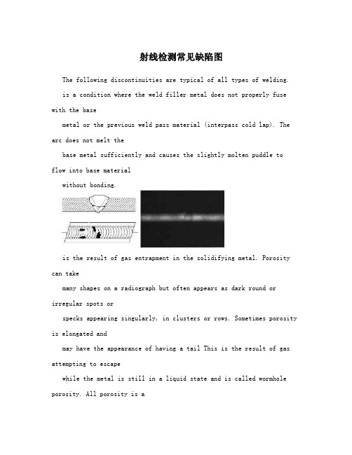
射线检测常见缺陷图The following discontinuities are typical of all types of welding.is a condition where the weld filler metal does not properly fuse with the basemetal or the previous weld pass material (interpass cold lap). The arc does not melt thebase metal sufficiently and causes the slightly molten puddle to flow into base materialwithout bonding.is the result of gas entrapment in the solidifying metal. Porosity can takemany shapes on a radiograph but often appears as dark round or irregular spots orspecks appearing singularly, in clusters or rows. Sometimes porosity is elongated andmay have the appearance of having a tail This is the result of gas attempting to escapewhile the metal is still in a liquid state and is called wormhole porosity. All porosity is avoid in the material it will have a radiographic density more than the surrounding area.(密集气孔)is caused when flux coated electrodes are contaminated with moisture. The moisture turns into gases when heated and becomes trapped in theweld during the welding process. Cluster porosity appear just like regular porosity in theradiograph but the indications will be grouped close together.are nonmetallic solid material entrapped in weld metal or between weld and base metal. In a radiograph, dark, jagged asymmetrical shapes within the weldor along the weld joint areas are indicative of slag inclusions.occurs when the weldmetal fails to penetrate the joint. It is one of the most objectionable weld discontinuities.Lack of penetration allows a natural stress riser from which a crack may propagate. Theappearance on a radiograph is a dark area with well-defined,straight edges that followsthe land or root face down the center of the weldment.(未融合)is a condition where the weld filler metal does not properly fuse with the base metal. Appearance on radiograph: usually appears as a dark line orlines oriented in the direction of the weld seam along the weld preparation or joiningarea.is condition where the weld metal has contracted as it cools and has been drawn up into the root of the weld. On a radiograph it lookssimilar to lack of penetration but the line has irregular edges and it is often quite wide inthe center of the weld image.is an erosion of the base metal next to the root of the weld. In the radiographic image it appears as a dark irregular line offset from the centerline of the weldment. Undercutting is not as straight edged as LOP because itdoes not follow a ground edge.is an erosion of the base metal next to the crownof the weld. In the radiograph, it appears as a dark irregular line along the outside edgeof the weld area.are terms associated with a condition where two pieces being welded together are not properly aligned. The radiographic image is a noticeabledifference in density between the two pieces. The difference in density is caused by thedifference in material thickness. The dark, straight line is caused by failure of the weldmetal to fuse with the land area.is an area of a weld where the thickness of weld metal deposited is less than the thickness of the base material. It is very easy to determine by radiograph if the weld has inadequate reinforcement, because the imagedensity in the area of suspected inadequacy will be more (darker) than the image densityof the surrounding base material.is an area of a weld that has weld metal added in excess of that specified by engineering drawings and codes. The appearance on a radiograph is a localized, lighter area in the weld. A visual inspection will easilydetermine if the weld reinforcement is in excess of that specified by the engineeringrequirements.can be detected in a radiograph only when they are propagating in a direction that produces a change in thickness that is parallel to the x-ray beam. Crackswill appear as jagged and often very faint irregular lines. Cracks can sometimes appearas "tails" on inclusions or porosity.The following discontinuities are peculiar to the TIG welding process. Thesediscontinuities occur in most metals welded by the process including aluminum andstainless steels. The TIG method of welding produces a clean homogeneous weld whichwhen radiographed is easily interpreted.Tungsten is a brittle and inherently dense material used inthe electrode in tungsten inert gas welding. If improper welding procedures are used,tungsten may be entrapped in the weld. Radiographically, tungsten is more dense thanaluminum or steel; therefore, it shows as a lighter area with a distinct outline on theradiograph.are usually visible on the surface of material being welded (especially aluminum). Oxide inclusions are less dense than the surrounding materials and,therefore, appear as dark irregularly shaped discontinuities in the radiograph.The following discontinuities are most commonly found in GMAW welds.are short lengths of weld electrode wire, visible on the top or bottom surface of the weld or contained within the weld. On a radiograph they appear as light, "wire like"indications.results when too much heat causes excessive weld metal topenetrate the weld zone. Often lumps of metal sag through the weld creating a thickglobular condition on the back of the weld. These globs of metal are referred to as icicles.On a radiograph, burn through appears as dark spots, which are often surrounded bylight globular areas (icicles).Radiograph Interpretation – CastingsThe major objective of radiographic testing of castings is the disclosure of defects that adversely affect the strength of the product. Casting are a product form that often receive radiographic inspection since many of the defects produced by the casting process are volumetric in nature and, thus, relatively easy to detect with this method. These discontinuities of course, are related to casting process deficiencies, which, if properly understood, can lead to accurate accept-rejectdecisions as well as to suitable corrective measures. Since different types and sizes of defects have different effects of the performance of the casting, it is important that the radiographer is able to identify the type and size of the defects. ASTM E155, Standard for Radiographs of castings has been produced to help the radiographer make a better assessment of the defects found components. The castings used to produce the standard radiographs have been destructively analyzed to confirm the size and type of discontinuities present. The following is a brief description of the most common discontinuity types included in existing reference radiograph documents (in graded types or as single illustrations).Gas porosity or blow holes are caused by accumulated gas or airwhich is trapped by the metal. These discontinuities are usually smooth-walled rounded cavities of a spherical, elongated or flattened shape. If thesprue is not high enough to provide the necessary heat transfer needed to force the gas or air out of the mold,the gas or air will be trapped as the molten metal begins to solidify. Blows can also be caused by sand that istoo fine, too wet, or by sand that has a low permeability so thatgas can't escape. Too high a moisture content inthe sand makes it difficult to carry the excessive volumes of water vapor away from the casting. Another causeof blows can be attributed to using green ladles, rusty or damp chills andchaplets.Sand inclusions and dross are nonmetallic oxides, appearing on the radiograph as irregular, dark blotches. These come from disintegrated portions of mold or core walls and/or from oxides (formed in the melt) whichhave not been skimmed off prior to introduction of the metal into the mold gates. Careful control of the melt,proper holding time in the ladle and skimming of the melt during pouring will minimize or obviate this sourceof trouble.Shrinkage is a form of discontinuity that appears as dark spots on the radiograph. Shrinkage assumes variousforms but in all cases it occurs because molten metal shrinks as it solidifies, in all portions of the final casting.Shrinkage is avoided by making sure that the volume of the casting is adequately fed by risers whichsacrificially retain the shrinkage. Shrinkage can be recognized in a number of characteristic by varyingappearances on radiographs. There are at least four types: (1) cavity; (2) dendritic; (3) filamentary; and (4)sponge types. Some documents designate these types by numbers, without actual names, to avoid possiblemisunderstanding.Cavity shrinkage appears as areas with distinct jagged boundaries. It may be produced when metal solidifiesbetween two original streams of melt, coming from oppositedirections to join a common front; cavityshrinkage usually occurs at a time when the melt has almost reached solidification temperature and there is nosource of supplementary liquid to feed possible cavities.is a distribution of very fine lines or small elongated cavitiesthat may vary in density and are usually unconnected.usually occurs as a continuous structure of connected lines or branches of variable length, width and density, or occasionally as a network.shows itself as areas of lacy texture with diffuse outlines, generally toward the mid-thickness of heavier casting sections. Sponge shrinkage may bedendritic or filamentary shrinkage; filamentary sponge shrinkage appears more blurredbecause it is projected through the relatively thick coating between the discontinuitiesand the film surface.are thin (straight or jagged) linearly disposed discontinuities that occur after the melt has solidified. They generally appear singly and originate at casting surfaces.generally appear on or near a surface of cast metal as a result of two streams of liquid meeting and failing to unite. They may appear on a radiograph as cracks orseams with smooth or rounded edges.Inclusions are nonmetallic materials in a supposedly solid metallic matrix. They may be less or more dense than the matrix alloy and willappear on the radiograph, respectively, as darker or lighter indications. The lattertype is more common in light metal castings.shows itself as a variation in section thickness, usually on radiographic viewsrepresenting diametrically opposite portions of cylindrical casting portions.are linearly disposed indications that represent fractures formed in a metalduring solidification because of hindered contraction. The latter may occur due to overlyhard (completely unyielding) mold or core walls. The effect of hot tears, as a stressconcentration, is similar to that of an ordinary crack; how tearsare usually systematicflaws. If flaws are identified as hot tears in larger runs of a casting type, they may call for explicit improvements in technique.appear on the radiograph as prominent dense areas of variable dimensions witha definite smooth outline. They are mostly random in occurrence and not readily eliminated by specific remedial actions in the process.is a radiographic indication that appears as an indistinct area of more or lessdense images. The condition is a diffraction effect that occurs on relatively vague, thin-section radiographs, most often with austenitic stainless steel. Mottling is caused by interaction of the object's grain boundary material with low-energy X-rays (300 kV or lower). Inexperienced interpreters may incorrectly consider mottling as indications of unacceptable casting flaws. Even experienced interpreters often have to check the condition by re-radiography from slightly different source-film angles. Shifts in mottling are then very pronounced, while true casting discontinuities change only slightly in appearance.Most common alloy castings require welding either in upgrading from defective conditions or in joining to other system parts. It is mainlyfor reasons of casting repair that these descriptions of the more common weld defects are provided here. The terms appear as indication types in ASTM E390. For additional information, see theNondestructive Testing Handbook, Volume 3, Section 9 on the "Radiographic Control ofWelds."is nonmetallic solid material entrapped in weld metal or betweenweld material andbase metal. Radiographically, slag may appear in various shapes,from long narrowindications to short wide indications, and in various densities,from gray to very dark.is a series of rounded gas pockets or voids in the weld metal, andis generally cylindrical or elliptical in shape.is a groove melted in the base metal at the edge of a weld and left unfilled by weld metal. It represents a stress concentration that often must be corrected, andappears as a dark indication at the toe of a weld., as the name implies, is a lack of weld penetration through thethickness of the joint (or penetration which is less than specified). It is located at thecenter of a weld and is a wide, linear indication.is lack of complete fusion of some portions of the metal in a weld jointwith adjacent metal; either base or previously deposited weld metal. On a radiograph,this appears as a long, sharp linear indication, occurring at the centerline of the weld jointor at the fusion line.is a convex or concave irregularity (on the surface of backing ring, strip, fused root or adjacent base metal) resulting from complete melting of a localized regionbut without development of a void or open hole. On a radiograph, melt-through generallyappears as a round or elliptical indication.is a void or open hole into a backing ring, strip, fused root or adjacent base metal.is an indication from a localized heat-affected zone or a change in surface contour of a finished weld or adjacent base metal. Arc strikes are caused by the heatgenerated when electrical energy passes between surfaces of the finished weld or basemetal and the current source.occurs in arc or gas welding as metal particles which are expelled during welding and which do not form part of the actual weld: weld spatter appears as manysmall, light cylindrical indications on a radiograph.is usually denser than base-metal particles. Tungsten inclusions appear most linear, very light radiographic images; accept/reject decisions for this defectare generally based on the slag criteria.is the condition of a surface which is heated during welding, resulting in oxide formation on the surface, due to partial or complete lack of purge of the weld atmosphere.Also called sugaring.shows the penetration of weld metal into the backing ring or into theclearance between backing ring or strip and thebase metal. It appears in radiographs as asharply defined film density transition.appears as an intermittent or continuous groove in the internal surface of thebase metal, backing ring or strip along the edge of the weld root.Real-time RadiographyReal-time radiography (RTR), or real-time radioscopy, is a nondestructive test (NDT)method whereby an image is produced electronically rather than on film so that very littlelag time occurs between the item being exposed to radiation and the resulting image. Inmost instances, the electronic image that is viewed, results from the radiation passingthrough the object being inspected and interacting with a screen of material thatfluoresces or gives off light when the interaction occurs. The fluorescent elements of thescreen form the image much as the grains of silver form the image in film radiography.The image formed is a "positive image" since brighter areas on the image indicate wherehigher levels of transmitted radiation reached the screen. This image is the opposite ofthe negative image produced in film radiography. In other words, with RTR, the lighter,brighter areas represent thinner sections or less dense sections of the test object.Real-time radiography is a well-established method of NDT having applications in automotive, aerospace, pressure vessel, electronic, andmunition industries, among others. The use of RTR is increasing due to a reduction in the cost of the equipment and resolution of issues such as the protecting and storing digital images. Since RTR is being used increasingly more, these educational materials were developed by the North Central Collaboration for NDT Education (NCCE) to introduce RTR to NDT technician students.。
射线检测—常见缺陷(无损检测课件)
8. 关于射线照相法特点的概括
射线检测的优点和局限性概括如下:
➢ (1)检测结果有直接记录——底片 底片上记录的信息十分丰富,且可以长期保存——记录最真 实、最直观、最全面、可追踪性最好的检测方法。
➢ (2)可以获得缺陷的投影图象,缺陷定性定量准确。 射线照相对缺陷定性是最准的。在定量方面,对体积型缺陷 (气孔、夹渣类)的长度、宽度尺寸的确定也很准,其误差 大致在零点几毫米。但对面积型缺陷(如裂纹、未熔合类), 如缺陷端部尺寸(高度和张口宽度)很小,则底片上影像尖 端延伸可能辨别不清,此时定量数据会偏小。
8. 关于射线照相法特点的概括
➢ (9)射线照相检测速度慢 一般情况下定向X射线机一次透照长度不超过300mm, 拍一张片子需10分钟,γ射线源的曝光时间一般更长。 射线照相从透照开始到评定出结果需数小时。
➢ (10)射线对人体有伤害 射线会对人体组织造成多种损伤,因此对职业放射性工 作人员剂量当量规定了限值。
➢ (6)有些试件结构和现场条件不适合射线照相。
8. 关于射线照相法特点的概括
➢ (7)对缺陷在工件中厚度方向的位置、尺寸(高度)的确定 比较困难
• 除了一些根部缺陷可结合焊接知识和规律来确定其在工件中厚度方向的 位置,很多缺陷无法用底片提供的信息定位。
• 缺陷高度可通过黑度对比的方法作出判断,但精确度不高,尤其影像细小 的裂纹类缺陷,其黑度测不准,用黑度对比方法测定缺陷高度的误差较大。
8. 关于射线照相法特点的概括
➢ (5)适宜检测对接焊缝,检测角焊缝效果较差,不适宜 检测板材、棒材、锻件。 检测角焊缝的透照布置比较困难,摄得底片的黑度变化 大,成像质量不够好;不适宜检验板材、棒材、锻件的 原因是板材、锻件中的大部分缺陷与板平行,射线照相 无法检出。此外棒材、锻件厚度较大,射线穿透比较困 难,效果也不好。
无损检测射线常见缺陷图集及分析-精选文档
纵向裂纹
根部裂纹
横向裂纹
6、咬边
一、常见缺陷及示意图
二、其他几种缺陷 三、常见伪缺陷
表 面 内 凹
根 部 内 凹
表 面 咬 边
内 咬 边
错 口
接 头 凹 坑
一、常见缺陷及示意图
二、其他几种缺陷 三、常见伪缺陷
1、压痕
1、压痕的表面现象是什么? 压痕的表征为密度明显低于邻近区域的密度。 2、它们产生的原因是什么? 在曝光前某个胶片区域局部受力严重。 3、这些现象何时可能发生? 产生压痕的主要原因在于暗袋准备过程中胶片处理的 方式不当。在处理过程中,胶片某处可能被压(夹)紧 在暗袋中。掉落到暗袋上的物体同样可能造成压痕。 4、如何检验压痕? 直接从同一包装盒中小心准备另一暗袋胶片,曝光并冲 洗胶片,如果未见到与第一次所见一样的暇疵,则第一次所 见的斑痕很可能就是压痕。 5、如何可以避免压痕? 严格遵守暗室操作规程,始终小心处理胶片,避免对胶 片施以任何类型的压力。
折 痕 曝 光 前
1、折痕的表面现象是什么? 折痕(曝光前)的表征为白月牙状显示,其密度低于邻近的胶片区域(黑度较低)。 2、它们产生的原因是什么? 曝光前弯曲胶片用力过大或过猛都会导致这种类型的折痕。 3、这些现象何时可能发生? 通常出现在从包装盒取出胶片或在曝光前装入暗袋时处理不当的情况下。 4、如何检验曝光前的折痕? 有意识地将某些胶片卷曲或扭折,使其曝光,然后按正常方法冲洗。检验胶片,这时您可 能会在胶片处理不当的地方风到一些颜色较淡的折痕。 5、如何可以避免它们? 严格遵守暗室操作规程,始终小心处理胶片,特别避免手指对胶片施以任何类型的压力。
2、折痕
折痕(曝光后)1
折痕(曝光后)2
折痕(曝光后)3
- 1、下载文档前请自行甄别文档内容的完整性,平台不提供额外的编辑、内容补充、找答案等附加服务。
- 2、"仅部分预览"的文档,不可在线预览部分如存在完整性等问题,可反馈申请退款(可完整预览的文档不适用该条件!)。
- 3、如文档侵犯您的权益,请联系客服反馈,我们会尽快为您处理(人工客服工作时间:9:00-18:30)。
板对接焊缝射线夹渣缺陷图谱
Rt缺陷图片101
板对接焊缝射线夹渣缺陷图谱
Rt缺陷图片102
板对接焊缝射线夹渣缺陷图谱
Rt缺陷图片103
板对接焊缝射线夹渣、气孔缺陷图谱
Rt缺陷图片104
板对接焊缝射线夹渣、气孔缺陷图谱
Rt缺陷图片105
板对接焊缝射线夹渣、气孔缺陷图谱
Rt缺陷图片106
板对接焊缝射线夹渣、未熔合缺陷图谱
Rt缺陷图片107
板对接焊缝射线夹渣缺陷图谱
Rt缺陷图片108
板对接焊缝射线夹渣缺陷图谱
Rt缺陷图片109
板对接焊缝射线夹渣缺陷图谱
Rt缺陷图片110
板对接焊缝射线夹渣、未熔合缺陷图谱
Rt缺陷图片111
板对接焊缝射线夹渣、未熔合缺陷图谱
Rt缺陷图片112
板对接焊缝射线夹渣、未熔合缺陷图谱
Rt缺陷图片113
板对接焊缝射线夹渣、未熔合缺陷图谱
Rt缺陷图片114
板对接焊缝射线夹渣缺陷图谱
Rt缺陷图片115
板对接焊缝射线夹渣缺陷图谱
Rt缺陷图片116
板对接焊缝射线夹渣缺陷图谱
Rt缺陷图片117
板对接焊缝射线夹钨缺陷图谱
Rt缺陷图片118
板对接焊缝射线未焊透缺陷图谱
Rt缺陷图片119
板对接焊缝射线未焊透缺陷图谱
Rt缺陷图片120