FDH3595中文资料
邵d硬度计

邵d硬度计
产品名称:LX-A型邵氏硬度计
∙产地:中国销售:沧州欧谱
∙简介:LX-A型橡胶硬度计广泛应用于中低硬度塑料、各类橡
胶、多元脂、皮革、蜡等的硬度测试。
∙
一、橡胶硬度计功能:
A型适用于一般橡胶、合成橡胶、软橡胶,多元脂、皮革、蜡等
C型适用于橡塑并用、塑料中含有发泡剂制成的微孔材料
D型适用于一般硬橡胶、树脂、压克力、玻璃、热塑性橡胶、印刷板、纤维等。
符合标准:DIN 53505,ASTM D2240 ISO/R868,JIS R7215;
执行标准:GB/T531-99,GB2411-80,HG/T2489-93,JJG304-2003
二、选型指南:
LX-A型硬度计,适用于普通硬度范围,低于20HA时,选用LX-AO型硬度计,高于90HA时,选用LX-D型硬度计;
LX-D型硬度计,适用于高硬度范围,低于20HD时,选用LX-A型硬度计;
LX-AO型硬度计,适用于低硬度橡胶和海绵;
LX-AM型硬度计,适用于普通硬度范围的薄样品,适用于厚度在1.5mm-6mm之间的样品;
HLX-A 、C 型橡胶硬度计测试机架。
74HC595完整中文资料
74HC595是8位串行输入/输出或者并行输出移位寄存器,具有 咼阻、关、断状态。
三态。特点8位串行输入8位串行或并行输出 存储状态寄存 器,三种状态输出寄存器可以直接清除100MHz的移位频率输出能 力 并行输出,总线驱动 串行输出;
标准 中等规模集成电路应用 串行到并行的数据转换Remote c ontrol holding register.描述595是告诉的硅结构的CMO器件,
CPD决 定动态的能耗,PD=CPD< VCC< f1 +刀(CLXVCC2< f0) F 1=输入频率,。1=输出电容f0=输出频率(MHZ Vcc=电源电压 引脚说明符号引脚描述
内部结构
结合引脚说明就能很快理解595的工作情况
功能表:
管脚编号
管脚名
管脚定义功能
1、2、3、4、5、6、
7、15
QA—QH
2)74595的主要优点是具有数据存储寄存器,在移位的过程中,输出 端的数据可以保持不变。这在串行速度慢的场合很有用处,数码管没 有闪烁感。
与164只有数据清零端相比,595还多有输出端时能/禁止控制 端,可以使输出为高阻态。
3)595是串入并出带有锁存功能移位寄存器,它的使用方法很简单, 在正常使用时SCLR为高电平,G为低电平。从SER每输入一位数据, 串行输595是串入并出带有锁存功能移位寄存器,它的使用方法很简 单,如下面的真值表,在正常使用时SCLF为高电平,G为低电平。 从SER每输入一位数据,串行输入时钟SCK上升沿有效一次,直到八 位数据输入完毕,输出时钟上升沿有效一次,此时,输入的数据就被
送到了输出端。入时钟SCK上升沿有效一次,直到八位数据输入完毕, 输出时钟上升沿有效一次,此时,输入的数据就被送到了输出端。
P89LPC935FA,129,P89LPC936FDH系列,P89LPC935FDH,529,P89LPC933FDH系列规格书,Datasheet 资料
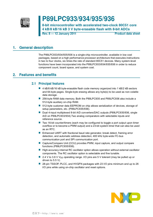
1. General descriptionThe P89LPC933/934/935/936 is a single-chip microcontroller, available in low costpackages, based on a high performance processor architecture that executes instructions in two to four clocks, six times the rate of standard 80C51 devices. Many system-level functions have been incorporated into the P89LPC933/934/935/936 in order to reduce component count, board space, and system cost.2. Features and benefits2.1Principal features4kB/8kB/16kB byte-erasable flash code memory organized into 1kB/2 kB sectorsand 64-byte pages. Single-byte erasing allows any byte(s) to be used as non-volatile data storage.256-byte RAM data memory. Both the P89LPC935 and P89LPC936 also include a512-byte auxiliary on-chip RAM.512-byte customer data EEPROM on chip allows serialization of devices, storage ofsetup parameters, etc. (P89LPC935/936).Dual 4-input multiplexed 8-bit A/D converters/DAC outputs (P89LPC935/936, singleA/D on P89LPC933/934).Two analog comparators with selectable inputs and reference source.Two 16-bit counter/timers (each may be configured to toggle a port output upon timeroverflow or to become a PWM output) and a 23-bit system timer that can also be used as an RTC.Enhanced UART with fractional baud rate generator, break detect, framing errordetection, and automatic address detection; 400kHz byte-wide I 2C-bus communication port and SPI communication port.Capture/Compare Unit (CCU) provides PWM, input capture, and output comparefunctions (P89LPC935/936).High-accuracy internal RC oscillator option allows operation without external oscillatorcomponents. The RC oscillator option is selectable and fine tunable.2.4V to3.6V V DD operating range. I/O pins are 5V tolerant (may be pulled up ordriven to 5.5V).28-pin TSSOP , PLCC, and HVQFN packages with 23 I/O pins minimum and up to 26I/O pins while using on-chip oscillator and reset options.P89LPC933/934/935/9368-bit microcontroller with accelerated two-clock 80C51 core 4 kB/8 kB/16 kB 3 V byte-erasable flash with 8-bit ADCsRev. 8 — 12 January 2011Product data sheet2.2Additional featuresA high performance 80C51 CPU provides instruction cycle times of 111ns to 222nsfor all instructions except multiply and divide when executing at 18MHz. This is sixtimes the performance of the standard 80C51 running at the same clock frequency. Alower clock frequency for the same performance results in power savings and reduced EMI.Serial flash In-Circuit Programming (ICP) allows simple production coding with commercial EPROM programmers. Flash security bits prevent reading of sensitiveapplication programs.Serial flash In-System Programming (ISP) allows coding while the device is mounted in the end application.In-Application Programming (IAP) of the flash code memory. This allows changing the code in a running application.Watchdog timer with separate on-chip oscillator, requiring no external components.The watchdog prescaler is selectable from eight values.Low voltage reset (brownout detect) allows a graceful system shutdown when power fails. May optionally be configured as an interrupt.Idle and two different power-down reduced power modes. Improved wake-up from Power-down mode (a LOW interrupt input starts execution). Typical power-downcurrent is 1μA (total power-down with voltage comparators disabled).Active-LOW reset. On-chip power-on reset allows operation without external reset components. A reset counter and reset glitch suppression circuitry prevent spuriousand incomplete resets. A software reset function is also available.Configurable on-chip oscillator with frequency range options selected by user programmed flash configuration bits. Oscillator options support frequencies from20kHz to the maximum operating frequency of 18MHz.Oscillator fail detect. The watchdog timer has a separate fully on-chip oscillator allowing it to perform an oscillator fail detect function.Programmable port output configuration options: quasi-bidirectional, open drain, push-pull, input-only.Port ‘input pattern match’ detect. Port0 may generate an interrupt when the value of the pins match or do not match a programmable pattern.LED drive capability (20mA) on all port pins. A maximum limit is specified for the entire chip.Controlled slew rate port outputs to reduce EMI. Outputs have approximately 10ns minimum ramp times.Only power and ground connections are required to operate theP89LPC933/934/935/936 when internal reset option is selected.Four interrupt priority levels.Eight keypad interrupt inputs, plus two additional external interrupt inputs.Schmitt trigger port inputs.Second data pointer.Emulation support.3. Product comparison overviewTable 1 highlights the differences between the four devices. For a complete list of device features please see Section 2 “Features and benefits”.4. Ordering information4.1Ordering optionsTable 1.Product comparison overviewDeviceFlash memory Sector size ADC1ADC0CCU Data EEPROM P89LPC933 4 kB 1 kB X ---P89LPC9348 kB 1 kB X ---P89LPC9358 kB 1 kB X X X X P89LPC93616 kB2 kBXXXXTable 2.Ordering informationType number Package NameDescriptionVersion P89LPC935FA PLCC28plastic leaded chip carrier; 28 leads SOT261-2P89LPC933HDH TSSOP28plastic thin shrink small outlinepackage; 28leads; body width 4.4mmSOT361-1P89LPC933FDH P89LPC934FDH P89LPC935FDH P89LPC936FDH P89LPC935FHNHVQFN28plastic thermal enhanced very thin quad flat package; no leads;28terminals; body 6×6×0.85mmSOT788-1Table 3.Ordering optionsType number Flash memory Temperature range Frequency P89LPC933HDH 4 kB −40°C to +125°C 0MHz to 18MHzP89LPC933FDH 4kB −40°C to +85°CP89LPC935FA 8kBP89LPC934FDH P89LPC935FDH P89LPC935FHN P89LPC936FDH16kB5. Block diagram6. Pinning information6.1Pinning6.2Pin descriptionTable 4.Pin descriptionSymbol Pin Type DescriptionTSSOP28,PLCC28HVQFN28P0.0 to P0.7I/O Port0: Port0 is an 8-bit I/O port with a user-configurable output type.During reset Port0 latches are configured in the input only mode with theinternal pull-up disabled. The operation of Port0 pins as inputs andoutputs depends upon the port configuration selected. Each port pin isconfigured independently. Refer to Section 8.13.1 “Port configurations”and Table 11 “Static characteristics” for details.The Keypad Interrupt feature operates with Port0 pins.All pins have Schmitt trigger inputs.Port0 also provides various special functions as described below:P0.0/CMP2/ KBI0/AD01327I/O P0.0 — Port0 bit0.O CMP2 — Comparator2 output.I KBI0 — Keyboard input0.I AD01 — ADC0 channel 1 analog input. (P89LPC935/936)P0.1/CIN2B/ KBI1/AD102622I/O P0.1 — Port0 bit1.I CIN2B — Comparator2 positive input B.I KBI1 — Keyboard input1.I AD10 — ADC1 channel 0 analog input.P0.2/CIN2A/ KBI2/AD112521I/O P0.2 — Port0 bit2.I CIN2A — Comparator2 positive input A.I KBI2 — Keyboard input2.I AD11 — ADC1 channel 1 analog input.P0.3/CIN1B/ KBI3/AD122420I/O P0.3 — Port0 bit3.I CIN1B — Comparator1 positive input B.I KBI3 — Keyboard input3.I AD12 — ADC1 channel 2 analog input.P0.4/CIN1A/ KBI4/DAC1/ AD132319I/O P0.4 — Port0 bit4.I CIN1A — Comparator1 positive input A.I KBI4 — Keyboard input4.O DAC1 — Digital-to-analog converter output 1.I AD13 — ADC1 channel 3 analog input.P0.5/ CMPREF/ KBI52218I/O P0.5 — Port0 bit5.I CMPREF — Comparator reference (negative) input.I KBI5 — Keyboard input5.P0.6/CMP1/ KBI62016I/O P0.6 — Port0 bit6.O CMP1 — Comparator1 output.I KBI6 — Keyboard input6.P0.7/T1/ KBI71915I/O P0.7 — Port0 bit7.I/O T1 — Timer/counter1 external count input or overflow output.I KBI7 — Keyboard input7.P1.0 to P1.7I/O, I [1]Port1: Port1 is an 8-bit I/O port with a user-configurable output type,except for three pins as noted below. During reset Port1 latches areconfigured in the input only mode with the internal pull-up disabled. Theoperation of the configurable Port1 pins as inputs and outputs dependsupon the port configuration selected. Each of the configurable port pinsare programmed independently. Refer to Section 8.13.1 “Portconfigurations” and Table 11 “Static characteristics” for details. P1.2 andP1.3 are open drain when used as outputs. P1.5 is input only.All pins have Schmitt trigger inputs.Port1 also provides various special functions as described below:P1.0/TXD1814I/O P1.0 — Port1 bit0.O TXD — Transmitter output for the serial port.P1.1/RXD1713I/O P1.1 — Port1 bit1.I RXD — Receiver input for the serial port.P1.2/T0/SCL128I/O P1.2 — Port1 bit2 (open-drain when used as output).I/O T0 — Timer/counter0 external count input or overflow output (open-drainwhen used as output).I/O SCL — I2C serial clock input/output.P1.3/INT0/ SDA 117I/O P1.3 — Port1 bit3 (open-drain when used as output).I INT0 — External interrupt0 input.I/O SDA — I2C serial data input/output.P1.4/INT1106I P1.4 — Port1 bit4.I INT1 — External interrupt1 input.P1.5/RST62I P1.5 — Port1 bit5 (input only).I RST — External reset input during power-on or if selected via UCFG1.When functioning as a reset input, a LOW on this pin resets themicrocontroller, causing I/O ports and peripherals to take on their defaultstates, and the processor begins execution at address0. Also used duringa power-on sequence to force ISP mode. When using an oscillatorfrequency above 12MHz, the reset input function of P1.5 must beenabled. An external circuit is required to hold the device in reset atpower-up until VDD has reached its specified level. When systempower is removed VDD will fall below the minimum specifiedoperating voltage. When using an oscillator frequency above12MHz, in some applications, an external brownout detect circuitmay be required to hold the device in reset when VDD falls below theminimum specified operating voltage.P1.6/OCB51I/O P1.6 — Port1 bit6.O OCB — Output Compare B. (P89LPC935/936)P1.7/OCC/ AD00428I/O P1.7 — Port1 bit7.O OCC — Output Compare C. (P89LPC935/936)I AD00 — ADC0 channel 0 analog input. (P89LPC935/936)Table 4.Pin description …continuedSymbol Pin Type Description TSSOP28,PLCC28HVQFN28P2.0 to P2.7I/OPort 2: Port 2 is an 8-bit I/O port with a user-configurable output type. During reset Port 2 latches are configured in the input only mode with the internal pull-up disabled. The operation of Port 2 pins as inputs and outputs depends upon the port configuration selected. Each port pin is configured independently. Refer to Section 8.13.1 “Port configurations” and Table 11 “Static characteristics” for details.All pins have Schmitt trigger inputs.Port 2 also provides various special functions as described below:P2.0/ICB/ DAC0/AD03125I/O P2.0 — Port 2 bit 0.I ICB — Input Capture B. (P89LPC935/936)I DAC0 — Digital-to-analog converter output.IAD03 — ADC0 channel 3 analog input. (P89LPC935/936)P2.1/OCD/ AD02226I/O P2.1 — Port 2 bit 1.O OCD — Output Compare D. (P89LPC935/936)IAD02 — ADC0 channel 2 analog input. (P89LPC935/936)P2.2/MOSI 139I/O P2.2 — Port 2 bit 2.I/OMOSI — SPI master out slave in. When configured as master, this pin is output; when configured as slave, this pin is input.P2.3/MISO 1410I/O P2.3 — Port 2 bit 3.I/OMISO — When configured as master, this pin is input, when configured as slave, this pin is output.P2.4/SS 1511I/O P2.4 — Port 2 bit 4.I SS — SPI Slave select.P2.5/ SPICLK 1612I/O P2.5 — Port 2 bit 5.I/OSPICLK — SPI clock. When configured as master, this pin is output; when configured as slave, this pin is input. P2.6/OCA 2723I/O P2.6 — Port 2 bit 6.O OCA — Output Compare A. (P89LPC935/936)P2.7/ICA2824I/O P2.7 — Port 2 bit 7.IICA — Input Capture A. (P89LPC935/936)Table 4.Pin description …continuedSymbolPinTypeDescriptionTSSOP28, PLCC28HVQFN28[1]Input/output for P1.0 to P1.4, P1.6, P1.7. Input for P1.5.P3.0 to P3.1I/OPort 3: Port 3 is a 2-bit I/O port with a user-configurable output type.During reset Port 3 latches are configured in the input only mode with the internal pull-up disabled. The operation of Port 3 pins as inputs and outputs depends upon the port configuration selected. Each port pin is configured independently. Refer to Section 8.13.1 “Port configurations” and Table 11 “Static characteristics” for details.All pins have Schmitt trigger inputs.Port 3 also provides various special functions as described below:P3.0/XTAL2/ CLKOUT95I/O P3.0 — Port 3 bit 0.O XTAL2 — Output from the oscillator amplifier (when a crystal oscillator option is selected via the flash configuration.OCLKOUT — CPU clock divided by 2 when enabled via SFR bit (ENCLK - TRIM.6). It can be used if the CPU clock is the internal RC oscillator, watchdog oscillator or external clock input, except when XTAL1/XTAL2 are used to generate clock source for the RTC/system timer.P3.1/XTAL184I/O P3.1 — Port 3 bit 1.IXTAL1 — Input to the oscillator circuit and internal clock generator circuits (when selected via the flash configuration). It can be a port pin if internal RC oscillator or watchdog oscillator is used as the CPU clock source, and if XTAL1/XTAL2 are not used to generate the clock for the RTC/system timer.V SS 73I Ground: 0V reference.V DD2117IPower supply: This is the power supply voltage for normal operation as well as Idle and Power-down modes.Table 4.Pin description …continuedSymbolPinTypeDescriptionTSSOP28, PLCC28HVQFN287. Logic symbols8. Functional descriptionRemark: Please refer to the P89LPC933/934/935/936 User manual for a more detailedfunctional description.8.1Special function registersRemark: SFR accesses are restricted in the following ways:•User must not attempt to access any SFR locations not defined.•Accesses to any defined SFR locations must be strictly for the functions for the SFRs.•SFR bits labeled ‘-’, logic 0 or logic 1 can only be written and read as follows:–‘-’ Unless otherwise specified, must be written with logic 0, but can return anyvalue when read (even if it was written with logic 0). It is a reserved bit and may beused in future derivatives.–Logic 0 must be written with logic 0, and will return a logic 0 when read.–Logic 1 must be written with logic 1, and will return a logic 1 when read.P89LPC933_934_935_936All information provided in this document is subject to legal disclaimers.© NXP B.V. 2011. All rights reserved.Product data sheet Rev. 8 — 12 January 2011 13 of 77NXP Semiconductors P89LPC933/934/935/9368-bit microcontroller with accelerated two-clock 80C51 coreTable 5.Special function registers - P89LPC933/934* indicates SFRs that are bit addressable. Name Description SFR addr.Bit functions and addresses Reset valueMSB LSB Hex Binary Bit address E7E6E5E4E3E2E1E0ACC*Accumulator E0H 0000000000ADCON0A/D control register 08EH -----ENADC0--0000000000ADCON1A/D control register 197H ENBI1ENADCI 1TMM1EDGE1ADCI1ENADC1ADCS11ADCS100000000000ADINS A/D input select A3H ADI13ADI12ADI11ADI10----0000000000ADMODA A/D mode register A C0H BNDI1BURST1SCC1SCAN1----0000000000ADMODB A/D mode register B A1H CLK2CLK1CLK0-ENDAC1ENDAC0BSA1-00000x 0000AD0DAT3A/D_0 data register 3F4H 0000000000AD1BH A/D_1 boundary high register C4H FF 11111111AD1BL A/D_1 boundary low register BCH 0000000000AD1DAT0A/D_1 data register 0D5H 0000000000AD1DAT1A/D_1 data register 1D6H 0000000000AD1DAT2A/D_1 data register 2D7H 0000000000AD1DAT3A/D_1 data register 3F5H 0000000000AUXR1Auxiliary function register A2H CLKLP EBRR ENT1ENT0SRST 0-DPS 00[1]000000x0Bit address F7F6F5F4F3F2F1F0B* B register F0H 0000000000BRGR0Baud rate generator rate low BEH 00[2]00000000BRGR1Baud rate generator rate high BFH 00[1][2]00000000BRGCON Baudrate generator control BDH ------SBRGS BRGEN 00[2]xxxx xx00CMP1Comparator 1 control register ACH --CE1CP1CN1OE1CO1CMF100[1]xx000000CMP2Comparator 2 control register ADH --CE2CP2CN2OE2CO2CMF200[1]xx000000DIVM CPU clock divide-by-M control95H 0000000000DPTR Data pointer (2bytes)DPH Data pointer high 83H 0000000000DPL Data pointer low 82H 0000000000FMADRH Program flash address high E7H 0000000000芯天下--/P89LPC933_934_935_936All information provided in this document is subject to legal disclaimers.© NXP B.V. 2011. All rights reserved.Product data sheet Rev. 8 — 12 January 2011 14 of 77NXP Semiconductors P89LPC933/934/935/9368-bit microcontroller with accelerated two-clock 80C51 core FMADRL Program flash address low E6H 0000000000FMCON Program flash control (Read)E4H BUSY ---HVA HVE SV OI 7001110000Program flash control (Write)E4H FMCMD.7FMCMD.6FMCMD.5FMCMD.4FMCMD.3FMCMD.2FMCMD.1FMCMD.FMDATA Program flash data E5H 0000000000I2ADR I 2C slave address register DBH I2ADR.6I2ADR.5I2ADR.4I2ADR.3I2ADR.2I2ADR.1I2ADR.0GC 0000000000Bit address DF DE DD DC DB DA D9D8I2CON*I 2C control register D8H -I2EN STA STO SI AA -CRSEL 00x00000x0I2DAT I 2C data register DAHI2SCLH Serial clock generator/SCL duty cycle register highDDH 0000000000I2SCLL Serial clock generator/SCL duty cycle register lowDCH 0000000000I2STAT I 2C status register D9H STA.4STA.3STA.2STA.1STA.0000F811111000ICRAH Input capture A register high ABH 0000000000ICRAL Input capture A register low AAH 0000000000ICRBH Input capture B register high AFH 0000000000ICRBL Input capture B register low AEH 0000000000Bit address AF AE AD AC AB AA A9A8IEN0*Interrupt enable 0A8H EA EWDRT EBO ES/ESR ET1EX1ET0EX00000000000Bit address EF EE ED EC EB EA E9E8IEN1*Interrupt enable 1E8H EAD EST --ESPI EC EKBI EI2C 00[3]00x00000Bit address BF BE BD BC BB BA B9B8IP0*Interrupt priority 0B8H -PWDRT PBO PS/PSR PT1PX1PT0PX000[3]x0000000IP0H Interrupt priority 0 high B7H -PWDRT H PBOH PSH/ PSRHPT1H PX1H PT0H PX0H 00[3]x0000000Bit address FF FE FD FC FB FA F9F8IP1*Interrupt priority 1F8H PAD PST --PSPI PC PKBI PI2C 00[3]00x00000IP1H Interrupt priority 1 high F7H PADH PSTH --PSPIH PCH PKBIH PI2CH 00[3]00x00000Table 5.Special function registers - P89LPC933/934 …continued* indicates SFRs that are bit addressable.Name Description SFR addr.Bit functions and addresses Reset valueMSB LSB Hex Binary芯天下--/P89LPC933_934_935_936All information provided in this document is subject to legal disclaimers.© NXP B.V. 2011. All rights reserved.Product data sheet Rev. 8 — 12 January 2011 15 of 77NXP Semiconductors P89LPC933/934/935/9368-bit microcontroller with accelerated two-clock 80C51 core KBCON Keypad control register 94H ------PATN _SELKBIF 00[3]xxxx xx00KBMASK Keypad interrupt mask register 86H 0000000000KBPATN Keypad pattern register 93H FF 11111111Bit address 8786858483828180P0*Port 080H T1/KB7CMP1/KB6CMPREF /KB5CIN1A /KB4CIN1B /KB3CIN2A /KB2CIN2B /KB1CMP2/KB0[3]Bit address 9796959493929190P1*Port 190H --RST INT1INT0/ SDAT0/SCL RXD TXD [3]Bit address A7A6A5A4A3A2A1A0P2*Port 2A0H --SPICLK SS MISO MOSI --[3]Bit address B7B6B5B4B3B2B1B0P3*Port 3B0H ------XTAL1XTAL2[3]P0M1Port 0 output mode 184H (P0M1.7)(P0M1.6)(P0M1.5)(P0M1.4)(P0M1.3)(P0M1.2)(P0M1.1)(P0M1.0)FF [3]11111111P0M2Port 0 output mode 285H (P0M2.7)(P0M2.6)(P0M2.5)(P0M2.4)(P0M2.3)(P0M2.2)(P0M2.1)(P0M2.0)00[3]00000000P1M1Port 1 output mode 191H (P1M1.7)(P1M1.6)-(P1M1.4)(P1M1.3)(P1M1.2)(P1M1.1)(P1M1.0)D3[3]11x1xx11P1M2Port 1 output mode 292H (P1M2.7)(P1M2.6)-(P1M2.4)(P1M2.3)(P1M2.2)(P1M2.1)(P1M2.0)00[3]00x0xx00P2M1Port 2 output mode 1A4H (P2M1.7)(P2M1.6)(P2M1.5)(P2M1.4)(P2M1.3)(P2M1.2)(P2M1.1)(P2M1.0)FF [3]11111111P2M2Port 2 output mode 2A5H (P2M2.7)(P2M2.6)(P2M2.5)(P2M2.4)(P2M2.3)(P2M2.2)(P2M2.1)(P2M2.0)00[3]00000000P3M1Port 3output mode 1B1H ------(P3M1.1)(P3M1.0)03[3]xxxx xx11P3M2Port 3 output mode 2B2H ------(P3M2.1)(P3M2.0)00[3]xxxx xx00PCON Power control register 87H SMOD1SMOD0BOPD BOI GF1GF0PMOD1PMOD00000000000PCONA Power control register A B5H RTCPD -VCPD ADPD I2PD SPPD SPD -00[3]00000000Bitaddress D7D6D5D4D3D2D1D0PSW*Program status word D0H CY AC F0RS1RS0OV F1P 0000000000PT0AD Port 0 digital input disable F6H --PT0AD.5PT0AD.4PT0AD.3PT0AD.2PT0AD.1-00xx00000x RSTSRC Reset source register DFH --BOF POF R_BK R_WD R_SF R_EX [4]RTCCON Real-time clock control D1H RTCF RTCS1RTCS0---ERTC RTCEN 60[3][5]011x xx00Table 5.Special function registers - P89LPC933/934 …continued* indicates SFRs that are bit addressable.Name Description SFR addr.Bit functions and addresses Reset valueMSB LSB Hex Binary芯天下--/P89LPC933_934_935_936All information provided in this document is subject to legal disclaimers.© NXP B.V. 2011. All rights reserved.Product data sheet Rev. 8 — 12 January 2011 16 of 77NXP Semiconductors P89LPC933/934/935/9368-bit microcontroller with accelerated two-clock 80C51 core RTCH Real-time clock register high D2H 00[5]00000000RTCL Real-time clock register low D3H 00[5]00000000SADDR Serial port address register A9H 0000000000SADEN Serial port address enable B9H 0000000000SBUF Serial Port data buffer register 99H xx xxxx xxxxBit address 9F 9E 9D 9C 9B 9A 9998SCON*Serial port control 98H SM0/FE SM1SM2REN TB8RB8TI RI 0000000000SSTAT Serial port extended status registerBAH DBMOD INTLO CIDIS DBISEL FE BR OE STINT 0000000000SP Stack pointer 81H 0700000111SPCTL SPI control register E2H SSIG SPEN DORD MSTR CPOL CPHA SPR1SPR00400000100SPSTAT SPI status register E1H SPIF WCOL ------0000xx xxxx SPDAT SPI data register E3H 0000000000TAMOD Timer 0 and 1 auxiliary mode 8FH ---T1M2---T0M200xxx0xxx0Bit address 8F 8E 8D 8C 8B 8A 8988TCON*Timer 0 and 1 control 88H TF1TR1TF0TR0IE1IT1IE0IT00000000000TH0Timer 0 high 8CH 0000000000TH1Timer 1 high 8DH 0000000000TL0Timer 0 low 8AH 0000000000TL1Timer 1 low 8BH 0000000000TMOD Timer 0 and 1 mode 89H T1GATE T1C/T T1M1T1M0T0GATE T0C/T T0M1T0M00000000000TRIM Internal oscillator trim register 96H RCCLK ENCLK TRIM.5TRIM.4TRIM.3TRIM.2TRIM.1TRIM.0[6] [5]WDCON Watchdog control register A7H PRE2PRE1PRE0--WDRUN WDTOF WDCLK [7] [5]Table 5.Special function registers - P89LPC933/934 …continued* indicates SFRs that are bit addressable.Name Description SFR addr.Bit functions and addresses Reset valueMSB LSB Hex Binary芯天下--/P89LPC933_934_935_936All information provided in this document is subject to legal disclaimers.© NXP B.V. 2011. All rights reserved.Product data sheet Rev. 8 — 12 January 2011 17 of 77NXP Semiconductors P89LPC933/934/935/9368-bit microcontroller with accelerated two-clock 80C51 core[1]Unimplemented bits in SFRs (labeled ’-’) are X (unknown) at all times. Unless otherwise specified, ones should not be written to these bits since they may be used for otherpurposes in future derivatives. The reset values shown for these bits are logic 0s although they are unknown when read.[2]BRGR1 and BRGR0 must only be written if BRGEN in BRGCON SFR is logic 0. If any are written while BRGEN =1, the result is unpredictable.[3]All ports are in input only (high-impedance) state after power-up.[4]The RSTSRC register reflects the cause of the P89LPC933/934/935/936 reset. Upon a power-up reset, all reset source flags are cleared except POF and BOF; the power-on resetvalue is xx110000.[5]The only reset source that affects these SFRs is power-on reset.[6]On power-on reset, the TRIM SFR is initialized with a factory preprogrammed value. Other resets will not cause initialization of the TRIM register.[7]After reset, the value is 111001x1, i.e., PRE2 to PRE0 are all logic 1, WDRUN =1 and WDCLK =1. WDTOF bit is logic 1 after watchdog reset and is logic 0 after power-on reset.Other resets will not affect WDTOF.WDL Watchdog load C1H FF 11111111WFEED1Watchdog feed 1C2HWFEED2Watchdog feed 2C3HTable 5.Special function registers - P89LPC933/934 …continued* indicates SFRs that are bit addressable.Name Description SFR addr.Bit functions and addresses Reset valueMSB LSB Hex Binary芯天下--/P89LPC933_934_935_936All information provided in this document is subject to legal disclaimers.© NXP B.V. 2011. All rights reserved.Product data sheet Rev. 8 — 12 January 2011 18 of 77NXP Semiconductors P89LPC933/934/935/9368-bit microcontroller with accelerated two-clock 80C51 coreTable 6.Special function registers - P89LPC935/936* indicates SFRs that are bit addressable. Name Description SFR addr.Bit functions and addresses Reset valueMSB LSB Hex BinaryBit address E7E6E5E4E3E2E1E0ACC*Accumulator E0H 0000000000ADCON0A/D control register 08EH ENBI0ENADCI 0TMM0EDGE0ADCI0ENADC0ADCS01ADCS000000000000ADCON1A/D control register 197H ENBI1ENADCI 1TMM1EDGE1ADCI1ENADC1ADCS11ADCS100000000000ADINS A/D input select A3H ADI13ADI12ADI11ADI10ADI03ADI02ADI01ADI000000000000ADMODA A/D mode register A C0H BNDI1BURST1SCC1SCAN1BNDI0BURST0SCC0SCAN00000000000ADMODB A/D mode register B A1H CLK2CLK1CLK0-ENDAC1ENDAC0BSA1BSA000000x 0000AD0BH A/D_0 boundary high register BBH FF 11111111AD0BL A/D_0 boundary low register A6H 0000000000AD0DAT0A/D_0 data register 0C5H 0000000000AD0DAT1A/D_0 data register 1C6H 0000000000AD0DAT2A/D_0 data register 2C7H 0000000000AD0DAT3A/D_0 data register 3F4H 0000000000AD1BH A/D_1 boundary high register C4H FF 11111111AD1BL A/D_1 boundary low register BCH 0000000000AD1DAT0A/D_1 data register 0D5H 0000000000AD1DAT1A/D_1 data register 1D6H 0000000000AD1DAT2A/D_1 data register 2D7H 0000000000AD1DAT3A/D_1 data register 3F5H 0000000000AUXR1Auxiliary function register A2H CLKLP EBRR ENT1ENT0SRST 0-DPS 00000000x0Bit address F7F6F5F4F3F2F1F0B* B register F0H 0000000000BRGR0[2]Baud rate generator rate low BEH 0000000000BRGR1[2]Baud rate generator rate high BFH 0000000000BRGCON Baudrate generator control BDH ------SBRGS BRGEN 00[2]xxxx xx00CCCRA Capture compare A control registerEAH ICECA2ICECA1ICECA0ICESA ICNFA FCOA OCMA1OCMA00000000000芯天下--/P89LPC933_934_935_936All information provided in this document is subject to legal disclaimers.© NXP B.V. 2011. All rights reserved.Product data sheet Rev. 8 — 12 January 2011 19 of 77NXP Semiconductors P89LPC933/934/935/9368-bit microcontroller with accelerated two-clock 80C51 core CCCRB Capture compare B control registerEBH ICECB2ICECB1ICECB0ICESB ICNFB FCOB OCMB1OCMB00000000000CCCRC Capture compare C control register ECH -----FCOC OCMC1OCMC000xxxx x000CCCRD Capture compare D control registerEDH -----FCOD OCMD1OCMD000xxxx x000CMP1Comparator 1 control register ACH --CE1CP1CN1OE1CO1CMF100[3]xx000000CMP2Comparator 2 control register ADH --CE2CP2CN2OE2CO2CMF200[3]xx000000DEECON Data EEPROM control registerF1H EEIF HVERR ECTL1ECTL0---EADR80E 00001110DEEDAT Data EEPROM data register F2H 0000000000DEEADR Data EEPROM address registerF3H 0000000000DIVM CPU clock divide-by-M control95H 0000000000DPTR Data pointer (2bytes)DPH Data pointer high 83H 0000000000DPL Data pointer low 82H 0000000000FMADRH Program flash address high E7H 0000000000FMADRL Program flash address low E6H 0000000000FMCON Program flash control (Read)E4H BUSY ---HVA HVE SV OI 7001110000Program flash control (Write)E4H FMCMD.7FMCMD.6FMCMD.5FMCMD.4FMCMD.3FMCMD.2FMCMD.1FMCMD.FMDATA Program flash data E5H 0000000000I2ADR I 2C slave address register DBH I2ADR.6I2ADR.5I2ADR.4I2ADR.3I2ADR.2I2ADR.1I2ADR.0GC 0000000000Bitaddress DF DE DD DC DB DA D9D8I2CON*I 2C control register D8H -I2EN STA STO SI AA -CRSEL 00x00000x0I2DAT I 2C data register DAHI2SCLH Serial clock generator/SCL duty cycle register highDDH 0000000000Table 6.Special function registers - P89LPC935/936 …continued* indicates SFRs that are bit addressable.Name Description SFR addr.Bit functions and addresses Reset valueMSB LSB Hex Binary芯天下--/。
XXXX年第37期(总第170期)节能-中国质量认证中心
节能、环保、节水产品认证企业获证信息公告二〇一〇年第三十七期(总第170期)节能产品认证获证企业信息:计算机制造商:Dell Inc.获证规格型号:PP37L, Vostro 1015, Vostro 1530:19.5VDC 3.34A (电源适配器:LA65NS2-01,LA65NE1-01)证书编号:CQC10701050928生效日期:2010-10-08有效期至:2013-10-08品牌:Dell制造商:Dell Inc.获证规格型号:P03S: 19.5VDC, 3.34A(电源适配器:65NE1-01 输入: 100-240VAC, 50-60Hz, 1.5A, 输出: 19.5VDC, 3.34A; 2.DA65NS3-00 输入:100-240VAC, 50-60Hz, 1.5A or 11-16VDC, 8.0A; 输出: 19.5VDC/3.34A; 3.HA65NE1-00 输入:100-240VAC,50-60Hz,1.5A 输出:19.5VDC,3.34A)证书编号:CQC09701032452生效日期:2010-10-08有效期至:2010-10-14品牌:Dell制造商:宏碁股份有限公司获证规格型号:PEW51 19VDC,4.74A or 3.42A(电源适配器:1.PA-1900-34;2.HP-A0652R3B;3.HP-A0904A3;4.PA-1650-22;5.ADP-65JH DB;6.ADP-65JH BB;7.ADP-90CD DB;8.ADP-65VH B;9.PA-1650-69;10.CPA09-A065N1)证书编号:CQC10701050907生效日期:2010-10-08有效期至:2013-10-08品牌:Acer制造商:苏州海尔信息科技有限公司获证规格型号:HDP-9021: 220VAC 50Hz 3A/4A证书编号:CQC10701050918生效日期:2010-10-09有效期至:2013-10-09品牌:海尔 Haier制造商:苏州海尔信息科技有限公司获证规格型号:HDP-9218: 220VAC 50Hz 3A证书编号:CQC10701050919生效日期:2010-10-09有效期至:2013-10-09品牌:海尔 Haier单路输出式交流-直流和交流-交流外部电源制造商:亚源科技股份有限公司获证规格型号:DA-36P12 输入:100-240VAC,50-60Hz,1.0A输出:12VDC,3A证书编号:CQC10701050838生效日期:2010-10-09有效期至:2013-10-09品牌:/显示器制造商:Dell Inc.获证规格型号:IN2020f, IN2020Mf:100-240V~, 50/60Hz, 1.5A 证书编号:CQC10701050926生效日期:2010-10-08有效期至:2013-10-08品牌:DELL制造商:Dell Inc.获证规格型号:IN1920f :100-240V~, 50-60Hz, 1.5A证书编号:CQC10701050920生效日期:2010-10-08有效期至:2013-10-08品牌:DELL制造商:Dell Inc.获证规格型号:E190Sf: 100-240VAC 50/60Hz 1.5A证书编号:CQC10701050921生效日期:2010-10-08有效期至:2013-10-08品牌:DELL制造商:Dell Inc.获证规格型号:P170Sf: 100-240VAC 1.5A 50/60Hz证书编号:CQC10701050913生效日期:2010-10-08品牌:DELL制造商:Dell Inc.获证规格型号:P190Sf: 100-240VAC 50/60Hz 1.5A证书编号:CQC10701050912生效日期:2010-10-08有效期至:2013-10-08品牌:DELL制造商:Hewlett-Packard Company获证规格型号:LA2306x输入: 100-240VAC 50/60Hz 1.0A证书编号:CQC10701050909生效日期:2010-10-08有效期至:2013-10-08品牌:HP制造商:Hewlett-Packard Company获证规格型号:LA2006x输入: 100-240VAC 50/60Hz 1.0A证书编号:CQC10701050922生效日期:2010-10-08有效期至:2013-10-08品牌:HP制造商:Hewlett-Packard Company获证规格型号:LA1951gl:AC 100-240V~ 50/60Hz 1.0A(1,0A) 证书编号:CQC10701050924生效日期:2010-10-08有效期至:2013-10-08品牌:HP制造商:Hewlett-Packard Company获证规格型号:LA1951gl:AC 100-240V~ 50/60Hz 1.0A证书编号:CQC10701050923生效日期:2010-10-08有效期至:2013-10-08品牌:HP制造商:Hewlett-Packard Company获证规格型号:LA2006x输入: 100-240VAC 50/60Hz 1.0A证书编号:CQC10701050925有效期至:2013-10-08品牌:HP制造商:Hewlett-Packard Company获证规格型号: LA1751g: 100-240VAC, 50/60Hz, 1.5A证书编号:CQC10701050910生效日期:2010-10-08有效期至:2013-10-08品牌:hp制造商:Hewlett-Packard Company获证规格型号:HSTND-3041-F, HSTND-3061-F: 100-240VAC 50/60Hz 1.2A证书编号:CQC10701050911生效日期:2010-10-08有效期至:2013-10-08品牌:Hp,Compaq制造商:Hewlett-Packard Company获证规格型号:LA2306x输入: 100-240VAC 50/60Hz 1.0A证书编号:CQC10701050927生效日期:2010-10-08有效期至:2013-10-08品牌:HP制造商:NEC Display Solutions,Ltd.获证规格型号:L468TQ,X461HB-2-G1(C)-T,X461HB-3-G1(C)-T 100-240VAC; 50/60Hz;5.6A-2.5A证书编号:CQC10701050888生效日期:2010-10-08有效期至:2013-10-08品牌:NEC制造商:惠普公司获证规格型号:LA2206x 100-240VAC 50/60Hz 1.6A证书编号:CQC10701050893生效日期:2010-10-08有效期至:2013-10-08品牌:HP,Compaq制造商:联想(北京)有限公司获证规格型号:L2363dwA: 100-240VAC 50/60Hz 1.5A证书编号:CQC10701050908有效期至:2013-10-08品牌:lenovo, lenovo联想中小型三相异步电动机制造商:无锡华达电机有限公司证书编号:CQC09701032159 生效日期:2010-10-09有效期至:2012-05-27品牌:华达/马拉松多联式空调(热泵)机组制造商:三菱重工海尔(青岛)空调机有限公司获证规格型号:外机:RFC335KX6-K 内机:RFTS22KX6, RFTS25KX6, RFTS28KX6, RFTS32KX6, RFTS36KX6, RFTS40KX6, RFTS45KX6, RFTS50KX6, RFTS56KX6, RFTSD22KX6, RFTSD25KX6, RFTSD28KX6, RFTSD32KX6, RFTSD36KX6, RFTSD40KX6, RFTSD45KX6, RFTSD50KX6, RFTSD56KX6, RFU40KX6, RFU45KX6, RFU50KX6, RFU56KX6, RFU63KX6, RFU71KX6, RFU80KX6, RFU90KX6, RFU100KX6, RFU112KX6, RFU125KX6, RFU140KX6, RFU150KX6, RFUD40KX6, RFUD45KX6, RFUD50KX6, RFUD56KX6, RFUD63KX6, RFUD71KX6, RFUD80KX6, RFUD90KX6, RFUD100KX6, RFUD112KX6, RFUD125KX6, RFUD140KX6, RFUD150KX6, RFUM22KX6, RFUM25KX6, RFUM28KX6, RFUM32KX6, RFUM36KX6, RFUM40KX6, RFUM45KX6, RFUM50KX6, RFUM56KX6, RFUM63KX6, RFUM71KX6, RFUM80KX6, RFUM90KX6, RFUM100KX6, RFUM112KX6, RFUM125KX6, RFUM140KX6, RFUM150KX6, RFUMD22KX6, RFUMD25KX6, RFUMD28KX6, RFUMD32KX6, RFUMD36KX6, RFUMD40KX6, RFUMD45KX6, RFUMD50KX6, RFUMD56KX6, RFUMD63KX6, RFUMD71KX6, RFUMD80KX6, RFUMD90KX6, RFUMD100KX6, RFUMD112KX6, RFUMD125KX6, RFUMD140KX6, RFUMD150KX6, RFUT22KX6, RFUT25KX6, RFUT28KX6, RFUT32KX6, RFUT36KX6, RFUT40KX6, RFUT45KX6, RFUT50KX6, RFUT56KX6, RFUT63KX6, RFUT71KX6, RFUTD22KX6, RFUTD25KX6, RFUTD28KX6, RFUTD32KX6, RFUTD36KX6, RFUTD40KX6, RFUTD45KX6, RFUTD50KX6, RFUTD56KX6, RFUTD63KX6, RFUTD71KX6, RFTW22KX6, RFTW25KX6, RFTW28KX6, RFTW32KX6, RFTW36KX6, RFTW40KX6, RFTW45KX6, RFTW50KX6, RFTW56KX6, RFT28KX6, RFT32KX6, RFT36KX6, RFT40KX6, RFT45KX6, RFT50KX6, RFT56KX6, RFT63KX6, RFT71KX6, RFT80KX6, RFT90KX6, RFT100KX6, RFT112KX6, RFT125KX6, RFT140KX6, RFT150KX6, RFTD28KX6, RFTD32KX6, RFTD36KX6, RFTD40KX6, RFTD45KX6, RFTD50KX6, RFTD56KX6, RFTD63KX6, RFTD71KX6, RFTD80KX6, RFTD90KX6, RFTD100KX6, RFTD112KX6, RFTD125KX6, RFTD140KX6, RFTD150KX6, RF71KX6, RF140KX6证书编号:CQC10701050887生效日期:2010-10-08有效期至:2013-10-08品牌:海尔制造商:三菱重工海尔(青岛)空调机有限公司获证规格型号:室外机:RFC504KX6室内机:RFTS22KX6、RFTS25KX6、RFTS28KX6、RFTS32KX6、RFTS36KX6、RFTS40KX6、RFTS45KX6、RFTS50KX6、RFTS56KX6、RFTSD22KX6、RFTSD25KX6、RFTSD28KX6、RFTSD32KX6、RFTSD36KX6、RFTSD40KX6、RFTSD45KX6、RFTSD50KX6、RFTSD56KX6、RFU40KX6、RFU45KX6、RFU50KX6、RFU56KX6、RFU63KX6、RFU71KX6、RFU80KX6、RFU90KX6、RFU100KX6、RFU112KX6、RFU125KX6、RFU140KX6、RFU150KX6、RFU224KX6、RFU280KX6、RFUD40KX6、RFUD45KX6、RFUD50KX6、RFUD56KX6、RFUD63KX6、RFUD71KX6、RFUD80KX6、RFUD90KX6、RFUD100KX6、RFUD112KX6、RFUD125KX6、RFUD140KX6、RFUD150KX6、RFUD224KX6、RFUD280KX6、RFUM22KX6、RFUM25KX6、RFUM28KX6、RFUM32KX6、RFUM36KX6、RFUM40KX6、RFUM45KX6、RFUM50KX6、RFUM56KX6、RFUM63KX6、RFUM71KX6、RFUM80KX6、RFUM90KX6、RFUM100KX6、RFUM112KX6、RFUM125KX6、RFUM140KX6、RFUM150KX6、RFUMD22KX6、RFUMD25KX6、RFUMD28KX6、RFUMD32KX6、RFUMD36KX6、RFUMD40KX6、RFUMD45KX6、RFUMD50KX6、RFUMD56KX6、RFUMD63KX6、RFUMD71KX6、RFUMD80KX6、RFUMD90KX6、RFUMD100KX6、RFUMD112KX6、RFUMD125KX6、RFUMD140KX6、RFUMD150KX6、RFUT22KX6、RFUT25KX6、RFUT28KX6、RFUT32KX6、RFUT36KX6、RFUT40KX6、RFUT45KX6、RFUT50KX6、RFUT56KX6、RFUT63KX6、RFUT71KX6、RFUTD22KX6、RFUTD25KX6、RFUTD28KX6、RFUTD32KX6、RFUTD36KX6、RFUTD40KX6、RFUTD45KX6、RFUTD50KX6、RFUTD56KX6、RFUTD63KX6、RFUTD71KX6、RFTW22KX6、RFTW25KX6、RFTW28KX6、RFTW32KX6、RFTW36KX6、RFTW40KX6、RFTW45KX6、RFTW50KX6、RFTW56KX6、RFT28KX6、RFT32KX6、RFT36KX6、RFT40KX6、RFT45KX6、RFT50KX6、RFT56KX6、RFT63KX6、RFT71KX6、RFT80KX6、RFT90KX6、RFT100KX6、RFT112KX6、RFT125KX6、RFT140KX6、RFT150KX6、RFTD28KX6、RFTD32KX6、RFTD36KX6、RFTD40KX6、RFTD45KX6、RFTD50KX6、RFTD56KX6、RFTD63KX6、RFTD71KX6、RFTD80KX6、RFTD90KX6、RFTD100KX6、RFTD112KX6、RFTD125KX6、RFTD140KX6、RFTD150KX6、RF71KX6、RF140KX6。
BY359-1500中文资料

Philips Semiconductors Product specificationDamper diode BY359-1500, BY359-1500Sfast, high-voltageFEATURESSYMBOL QUICK REFERENCE DATA• Low forward volt drop • Fast switching• Soft recovery characteristic• High thermal cycling performance • Low thermal resistanceGENERAL DESCRIPTIONPINNINGSOD59 (TO220AC)Glass-passivated double diffused PIN DESCRIPTION rectifier diode featuring low forward voltage drop,fast reverse recovery 1cathode and soft recovery characteristic.The device is intended for use in TV 2anode receivers and PC monitors.tabcathodeThe BY359series is supplied in the conventional leaded SOD59(TO220AC)package.LIMITING VALUESLimiting values in accordance with the Absolute Maximum System (IEC 134).SYMBOL PARAMETERCONDITIONSMIN.MAX.UNIT V RSM Peak non-repetitive reverse -1500V voltageV RRM Peak repetitive reverse voltage -1500V V RWM Crest working reverse voltage -1300V I F(peak)Peak forward current16-32kHz TVBY359-1500 -10A 31-70kHz monitor BY359-1500S-7A I F(RMS)RMS forward current-15.7A I FRM Peak repetitive forward current sinusoidal; a = 1.57-60A I FSMPeak non-repetitive forward t = 10 ms -60A currentt = 8.3 ms-66A sinusoidal; T j = 150 ˚C prior to surge;with reapplied V RWM(max)T stg Storage temperature-40150˚C T jOperating junction temperature-150˚CTHERMAL RESISTANCESSYMBOL PARAMETERCONDITIONSMIN.TYP.MAX.UNIT R th j-mb Thermal resistance junction to -- 2.0K/W mounting baseR th j-aThermal resistance junction to in free air.-60-K/Wambient1tab2Philips Semiconductors Product specificationDamper diode BY359-1500, BY359-1500Sfast, high-voltageSTATIC CHARACTERISTICST j = 25 ˚C unless otherwise statedBY359-1500BY359-1500S SYMBOL PARAMETER CONDITIONS TYP.MAX.TYP.MAX.UNIT V F Forward voltage I F = 20 A1.3 1.8 1.52.0V I F = 10 A; T j = 150˚C 1.00 1.5 1.25 1.75V I RReverse currentV R = 1300 V 1010010100µA V R = 1300 V;50300100600µAT j = 100 ˚CDYNAMIC CHARACTERISTICST j = 25 ˚C unless otherwise statedBY359-1500BY359-1500S SYMBOL PARAMETERCONDITIONS TYP.MAX.TYP.MAX.UNIT t rr Reverse recovery time I F = 2 A; V R ≥ 30 V;0.470.600.280.35µs Q s Reverse recovery charge -dI F /dt = 20 A/µs 1.6 2.00.700.95µC V frPeak forward recovery voltageI F = 10 A;11.0-17.0-VdI F /dt = 30 A/µsPhilips Semiconductors Product specificationDamper diode BY359-1500, BY359-1500Sfast, high-voltagePhilips Semiconductors Product specificationDamper diode BY359-1500, BY359-1500Sfast, high-voltageMECHANICAL DATANotes1. Refer to mounting instructions for TO220 envelopes.2. Epoxy meets UL94 V0 at 1/8".Philips Semiconductors Product specification Damper diode BY359-1500, BY359-1500S fast, high-voltageDEFINITIONSData sheet statusObjective specification This data sheet contains target or goal specifications for product development. Preliminary specification This data sheet contains preliminary data; supplementary data may be published later. Product specification This data sheet contains final product specifications.Limiting valuesLimiting values are given in accordance with the Absolute Maximum Rating System (IEC 134). Stress above one or more of the limiting values may cause permanent damage to the device. These are stress ratings only and operation of the device at these or at any other conditions above those given in the Characteristics sections ofthis specification is not implied. Exposure to limiting values for extended periods may affect device reliability. Application informationWhere application information is given, it is advisory and does not form part of the specification.© Philips Electronics N.V. 1998All rights are reserved. Reproduction in whole or in part is prohibited without the prior written consent of the copyright owner.The information presented in this document does not form part of any quotation or contract, it is believed to be accurate and reliable and may be changed without notice. No liability will be accepted by the publisher for any consequence of its use. Publication thereof does not convey nor imply any license under patent or other industrial or intellectual property rights.LIFE SUPPORT APPLICATIONSThese products are not designed for use in life support appliances, devices or systems where malfunction of these products can be reasonably expected to result in personal injury. Philips customers using or selling these products for use in such applications do so at their own risk and agree to fully indemnify Philips for any damages resulting from such improper use or sale.。
AO4459中文资料

AO4459中⽂资料SymbolTyp Max 33406275R θJL 1824Maximum Junction-to-Lead CSteady-State°C/WThermal Characteristics ParameterUnits Maximum Junction-to-AmbientAt ≤ 10s R θJA °C/W Maximum Junction-to-Ambient ASteady-State °C/W AO4459AO4459SymbolMin TypMaxUnits BV DSS -30V -1T J =55°C-5I GSS ±100nA V GS(th)-1.5-1.85-2.5V I D(ON)-30A 3846T J =125°C53685872m ?g FS 11S V SD -0.78-1V I S-3.5A C iss 668830pF C oss 126pF C rss 92pF R g69?Q g (10V)12.716nC Q g (4.5V) 6.4nC Q gs 2nC Q gd 4nC t D(on)7.7ns t r 6.8ns t D(off)20ns t f 10ns t rr 2230ns Q rr15nCTHIS PRODUCT HAS BEEN DESIGNED AND QUALIFIED FOR THE CONSUMER MARKET. APPLICATIONS OR USES AS CRITICAL COMPONENTS IN LIFE SUPPORT DEVICES OR SYSTEMS ARE NOT AUTHORIZED. AOS DOES NOT ASSUME ANY LIABILITY ARISING OUT OF SUCH APPLICATIONS OR USES OF ITS PRODUCTS. AOS RESERVES THE RIGHT TO IMPROVE PRODUCT DESIGN,FUNCTIONS AND RELIABILITY WITHOUT NOTICE.DYNAMIC PARAMETERS Maximum Body-Diode Continuous CurrentGate resistanceV GS =0V, V DS =0V, f=1MHzV GS =0V, V DS =-15V, f=1MHz Input Capacitance Output Capacitance Turn-On Rise Time Turn-Off DelayTime V GS =-10V, V DS =-15V, R L =2.5?, R GEN =3?Turn-Off Fall TimeTurn-On DelayTime SWITCHING PARAMETERSTotal Gate Charge (4.5V)Gate Source Charge Gate Drain Charge Total Gate Charge (10V)V GS =-10V, V DS =-15V, I D =-6.5Am ?V GS =-4.5V, I D =-5AI S =-1A,V GS =0V V DS =-5V, I D =-6.5AR DS(ON)Static Drain-Source On-ResistanceForward TransconductanceDiode Forward VoltageI DSS µA Gate Threshold Voltage V DS =V GS I D =-250µA V DS =-24V, V GS =0VV DS =0V, V GS =±20V Zero Gate Voltage Drain Current Gate-Body leakage current Electrical Characteristics (T J =25°C unless otherwise noted)STATIC PARAMETERS ParameterConditions Body Diode Reverse Recovery Time Body Diode Reverse Recovery ChargeI F =-6.5A, dI/dt=100A/µsDrain-Source Breakdown Voltage On state drain currentI D =-250µA, V GS =0V V GS =-10V, V DS =-5V V GS =-10V, I D =-6.5AReverse Transfer Capacitance I F =-6.5A, dI/dt=100A/µs A: The value of R θJA is measured with the device mounted on 1in 2FR-4 board with 2oz. Copper, in a still air environment with T A =25°C. The value in any a given application depends on the user's specific board design. The current rating is based on the t ≤ 10s thermal resistance rating.B: Repetitive rating, pulse width limited by junction temperature.C. The R θJA is the sum of the thermal impedence from junction to lead R θJL and lead to ambient.D. The static characteristics in Figures 1 to 6 are obtained using < 300µs pulses, duty cycle 0.5% max.E. These tests are performed with the device mounted on 1 in 2FR-4 board with 2oz. Copper, in a still air environment with T A =25°C. The SOA curve provides a single pulse rating. Rev0 Sept 2006AO4459AO4459。
74435561100;中文规格书,Datasheet资料

74435561100
DATUM / DATE : 2009-11-02 Gurtspezifikation / Tape specification:
G H
SPEICHERDROSSEL WE-HCI POWER-CHOKE WE-HCI
I Rollenspezifikation / tape and reel specification:
74435561100
DATUM / DATE : 2009-11-02
SPEICHERDROSSEL WE-HCI POWER-CHOKE WE-HCI
H Induktivitätskurve / Inductance curve:
Induktivität vs Strom (typ.) Inductance vs Current (typ.)
08-09-29
Geprüft / checked
Kontrolliert / approved
Datum / date
D-74638 Waldenburg · Max-Eyth-Strasse 1 - 3 · Germany · Telefon (+49) (0) 7942 - 945 - 0 · Telefax (+49) (0) 7942 - 945 - 400 http://www.we-online.de
12,00
10,00
8,00
L (µH)
6,00
4,00
2,00
0,00 0 5 10 15 Current (A) 20 25 30 35
Freigabe erteilt / general release:
..................................................................................
FD470中文资料

FICHE TECHNIQUEFD400 RELAIS HERMETIQUE 2 RT DOUBLE COUPURE10 A/56 VccNOTES D'APPLICATION:001007SOCLE ASSOCIE:SFD400CE40ERelais hermétique monostable polariséCombinaison des contacts 2 R(DC) + 2 T(DE)Alimentation bobine Courant continuCARACTERISTIQUES TECHNIQUES PRINCIPALESPrévu pour commuter10 A / 56 VccMasse80 g maxDimensions max. du boîtier enmm26 x 25,7 x 26Armature à forces équilibréesBoîtier métallique hermétique protégé anti-corrosionNon chevauchement des contactsCARACTERISTIQUES ELECTRIQUES DES CONTACTSDurée de vie minimale Tension aux bornes du contact56 Vcc100 000 cycles20 000 cyclesPouvoir de commutation en Ampèressur charge résistivesur charge inductive (L/R=5ms)10650 cycles surcharge résistive40400 000 cycles sous 25% de la charge nominale résistiveLEACH®INTERNATIONALSolutions for Power Switching and ControlNorth America6900 Orangethorpe Ave.P.O. Box 5032Buena Park, CA 90622 USATel: (01) 714-736-7599Fax: (01) 714-670-1145Europe, SA2 Rue Goethe57430 SarralbeFranceTel: (33) 3 87 97 98 97Fax: (33) 3 87 97 84 04Asia-Pacific Ltd.20/F Shing Hing Commercial Bldg.21-27 Wing Kut StreetCentral, Hong KongTel: (852) 2 191 2886Fax: (852) 2 389 5803CARACTERISTIQUES DES BOBINES (Vcc)FD400 CODE A B C E N V Tension nominale (Un)281264828110 Tension maximale291475029125 Tension maximale d'enclenchement à +125° C19,810534,119,875 Tension de déclenchement assuré à -65° C1,50,50,221,55Résistance de la bobine en Ω ±10% à +25° C29070189552905000 Circuit suppresseur (Vcc)N/A N/A N/A N/A-42N/ACARACTERISTIQUES GENERALESGamme de température-65°C à +125°CRigidité diélectrique au niveau de la mer- Entre contacts et masse et entre contacts1250 Veff / 50 Hz- Entre bobine et masse1000 Veff / 50 Hz Rigidité diélectrique à 25 000 m (tous points)350 Veff / 50 HzRésistance d'isolement initiale sous 500 Vcc100 M Ω min Vibrations sinusoïdales (Sauf fixation G, O et R)30 G / 75 à 3000 Hz Vibrations sinusoïdales (uniquement fixation G, O et R)20 G / 75 à 3000 Hz Chocs (sauf fixation G, O et R)200 G / 6 msChocs (uniquement fixation G, O et R)100 G / 6 msDurée maximum d'ouverture des contacts sous l'influence des vibrations et chocs10 µsTemps d'enclenchement sous tension nominale15 ms maxTemps de déclenchement15 ms maxTemps de rebonds 1 ms maxChute de tension dans le contact sous courant nominal- Valeur initiale200 mV maxTYPES DE FIXATIONS FD400Dimensions en mmTolérances générales: ±0,25mmLa fixation k peut être utilisée avec les types de sorties 1 ou 8; elle inlut la fourniture de la cale isolante 10124TYPES DE SORTIESSCHEMA FD400SYSTEME DE REFERENCESFD400 J 2 NRéférence de base_________________________________| | | |1-Fixation (A,B,C,D,G,J,K,O,R)__________________________| | |2-Type de sortie (1,2,4,8)__________________________________| |3-Code bobine (A,B,C,E,N,V)_____________________________________|REMARQUES1. Les relais avec fixations B, D et la sortie 4 sont compatibles avec les socles des familles S400, SF400 et SFD 400.2. Possibilité de cales isolantes.3. Autres fixations ou sorties: nous consulter.CARACTERISTIQUES TYPIQUES DONNEES A TITRE INDICATIFq Variation de la résistance bobine en température: Voir note d'application n° 001q Constante de temps L/R des bobines: 11 msNote d'application N°001CORRECTION LIEE A LA VARIATION DE LA RESISTANCEDU CUIVRE EN FONCTION DE LA TEMPERATUREExemple: Le catalogue donne une résistance à 25°C de 935 ohms. Quelle valeur à 125°C?Le coefficient correcteur sur I'abaque est de 1,39 à 125°C. R devient: 935x1.39=1299 OhmsLa correction s'applique à la résistance bobine ainsi qu'aux tensions de fonctionnementNote d'application N°007DISPOSITIFS D'ECRETAGE POUR RELAISLes bobines de relais sont inductives, c'est ce qui leur permet de créer les efforts et les mouvements qui font fonctionner les contacts. Lorsque la tension est appliquée sur une bobine, le courant qui s'établit génère le flux magnétique créateur del'effort. A la coupure du circuit, la variation de flux inverse génère une tension qui tend à maintenir le courant qui circulait dans la bobine. La tension générée dépend essentiellement du dispositif de coupure. Plus cette coupure est rapide plus la surtension est élevée. Tous les dispositifs de limitation sont basés sur un ralentissement de la vitesse de décroissance du courant.Cette réduction peut présenter l'inconvénient de ralentir également le mouvement interne du relais, donc les conditionsd'ouverture des contacts, avec de ce fait, répercussion sur la durée de vie et la fiabilité.Il est donc important lors de la définition des dispositifs de commande des bobines de bien comprendre ces phénomènes. Caractéristiques typiques des bobinesSur le diagramme ci-contre, la courbe supérieure indique l'état des contacts. (état haut travail, état bas repos, étatintermédiaire en transfert). La courbe inférieure montre la tension qui apparait au bornes de la bobine lorsque le courant est coupé par un contact de relais.La surtension est écrêtée à -300V par la décharge luminescente qui se produit aux bornes de ces contacts. L'écrêtage a une durée de 200 µs après laquelle les variations de courant ne génèrent plus une tension suffisante. La tension décroît jusqu'au début du mouvement de l'équipage mobile, à ce moment la tension remonte du fait de la libération d'énergie des ressorts de contact travail. La tension chute pendant le transfert, puis croît de nouveau, lorsque le circuit magnétique se referme surl'aimant permanent.Les temps d'ouverture se décomposent en:- Temps jusqu'au début de mouvement: 1,5ms- Temps total de mouvement: 2,3ms- Temps de transfert: 1,4msLes différents types d'écrêteurDispositifs passifsLe circuit résistance - capacitéIl élimine le problème de la dissipation, ainsi que les fronts rapides de tension. Avec une bonne adaptation entre capacité et self, il ne ralentit pas l'ouverture. Dans certain cas de relais polarisés l'ouverture peut même être accélérée. La valeur de la capacité peut être calculée en utilisant la formule approximative:C =0,02 x T avec T = temps de réponse à l'enclenchement en ms R = résistance bobine en KOhmsR C = capacité en µFaradLa résistance série doit être comprise entre 0,5 et 1 fois la résistance bobine. Dans le cas de bobine de faible résistance, il faut faire attention au courant de charge de la capacité.Dans l'exemple ci-contre, effectué avec le même relais que précédemment, les temps deviennent:- Temps jusqu'au début du mouvement: 2,2 ms- Temps de transfert: 1,2 msIl y a donc eu une légère accélération de la vitesse de transfert.L'inconvénient principal réside dans le volume de la capacité. Notre exemple utilise un relais à bobine 290 Ohms et temps de réponse 8 ms. On trouve C=0,5 µF. Cette capacité non polarisée de 63 V au minimum, a un volume d'environ 3cm3.L'enroulement bifiliaireLe principe est de disposer, sur le circuit magnétique de la bobine principale, un second enroulement mis en court-circuit. Par une bonne adaptation de la résistance secondaire il est possible de trouver un compromis acceptable entre la surtension et le ralentissement. Cette méthode purement interne au relais présente des difficultés technologiques de réalisation. Pour être efficace aux variations rapides, le couplage entre les deux enroulements doit être parfait. Ceci implique pratiquement des enroulements imbriqués. Le volume occupé par le second enroulement diminue l'efficacité, et donc augmente la puissance nécessaire. Cette méthode ne peut être appliquée efficacement qu'à des produits étudiés spécifiquement pour cette caractéristique.La résistance (en parallèle sur la bobine)Pour présenter une certaine efficacité, la résistance doit être du même ordre de grandeur que la résistance de la bobine. Une résistance de 1,5 fois la bobine va limiter à 1,5 fois la tension d'alimentation. Le temps et la vitesse de retombé sont affectés modérement. L'inconvénient majeur est la puissance dissipée.Les dispositifs à semi-conducteursLa diodeC'est la méthode la plus simple et qui supprime toute surtension. Elle présente toutefois un inconvénient majeur qui est le ralentissement maximum de la vitesse d'ouverture. En effet la diode recycle la totalité de l'énergie dans la bobine elle-même. Le relevé ci-contre est toujours pris sur le même relais. Les temps indiqués par la courbe 2 deviennent:Temps jusqu'au début du mouvement: 14msTemps de transfert: 5msCes temps sont donc multipliés par un coefficient de 4 à 8.La courbe 1 montre le courant dans la bobine. La remonté indique la libération d'énergie des contacts travail. Au moment òu ils s'ouvrent, le courant redevient constant indiquant une ouverture des contacts à vitesse pratiquement nulle.Il résulte de ces caractéristiques que ce type d'écrêtage est absolument à proscrire pour les relais de puissance avec aimant de polarisation. Pour les petits relais ayant à commuter des courants faibles inférieurs à 0,2 A, la dégradation de durée de sa vie n'est pas significative, et la méthode est acceptable.Le réseau diode + résistanceIl permet d'éliminer l'inconvénient résistance seule cité précédemment, et de limiter l'inconvénient diode seule. Il est maintenant préférable d'utiliser le réseau diode + zener.Le réseau diode + zenerComme la résistance, la zener accélère la vitesse de décroissance du courant. En plus elle introduit un seuil de conduction qui permet d'éviter le recyclage de la libération d'énergie lors du mouvement de l'élément mobile.L'enregistrement ci-contre met en évidence ces caractéristiques. La courbe 1 monte la tension qui est écrêtée à -42 V. Les 2 remontées de tension lors de l'ouverture sont inférieures au seuil de conduction.Les temps d'ouverture se décomposent en:- Temps jusqu'au début du mouvement: 2,6ms- Temps total de mouvement: 2,4ms- Temps de transfert: 1,4msLa vitesse d'ouverture des contacts est donc inchangée.FICHE TECHNIQUE SFD400CE40ESOCLE POUR FD400/FD470 RELAISFAMILLE DE SOCLES POUR:Relais FD400 et FD470Socle pour montage sur circuit impriméCARACTERISTIQUES GENERALESTempérature d'utilisation-55°C à +125°CTempérature de stockage-70°C à +150°CResistance d'isolement> 1000 MΩRigidité diélectrique- Entre broches et fixations1500 Vrms / 50 Hz- Entre broches1500 Vrms / 50 HzVibrations sinusoïdales 20 g / 10 à 2000 HzChocs50 g / 11 msFixations livrées 6 vis M3-5. 6 rondelles onduflexLEACH®INTERNATIONAL Solutions for Power Switching and Control North America6900 Orangethorpe Ave.P.O. Box 5032Buena Park, CA 90622 USAEurope, SA2 Rue Goethe57430 SarralbeFranceAsia-Pacific Ltd.20/F Shing Hing Commercial Bldg.21-27 Wing Kut StreetCentral, Hong Kong。
- 1、下载文档前请自行甄别文档内容的完整性,平台不提供额外的编辑、内容补充、找答案等附加服务。
- 2、"仅部分预览"的文档,不可在线预览部分如存在完整性等问题,可反馈申请退款(可完整预览的文档不适用该条件!)。
- 3、如文档侵犯您的权益,请联系客服反馈,我们会尽快为您处理(人工客服工作时间:9:00-18:30)。
FDH3595 DO-35
ã1997 Fairchild Semiconductor Corporation
FDH3595
TRADEMARKS
ACEx™CoolFET™
CROSSVOLT™E 2CMOS TM FACT™
FACT Quiet Series™FAST ®FASTr™GTO™HiSeC™
The following are registered and unregistered trademarks Fairchild Semiconductor owns or is authorized to use and is not intended to be an exhaustive list of all such trademarks.
LIFE SUPPORT POLICY
FAIRCHILD’S PRODUCTS ARE NOT AUTHORIZED FOR USE AS CRITICAL COMPONENTS IN LIFE SUPPORT
DEVICES OR SYSTEMS WITHOUT THE EXPRESS WRITTEN APPROV AL OF FAIRCHILD SEMICONDUCTOR CORPORA TION.As used herein:
ISOPLANAR™MICROWIRE™POP™
PowerTrench™QS™
Quiet Series™SuperSOT™-3SuperSOT™-6SuperSOT™-8TinyLogic™
1. Life support devices or systems are devices or systems which, (a) are intended for surgical implant into
the body, or (b) support or sustain life, or (c) whose
failure to perform when properly used in accordance
with instructions for use provided in the labeling, can be reasonably expected to result in significant injury to the user.
2. A critical component is any component of a life
support device or system whose failure to perform can be reasonably expected to cause the failure of the life support device or system, or to affect its safety or effectiveness.PRODUCT STATUS DEFINITIONS Definition of Terms
Datasheet Identification Product Status Definition Advance Information
Preliminary No Identification Needed Obsolete This datasheet contains the design specifications for product development. Specifications may change in any manner without notice.
This datasheet contains preliminary data, and
supplementary data will be published at a later date.Fairchild Semiconductor reserves the right to make changes at any time without notice in order to improve design.
This datasheet contains final specifications. Fairchild Semiconductor reserves the right to make changes at any time without notice in order to improve design.
This datasheet contains specifications on a product that has been discontinued by Fairchild semiconductor.The datasheet is printed for reference information only.
Formative or In Design
First Production
Full Production
Not In Production
DISCLAIMER
FAIRCHILD SEMICONDUCTOR RESERVES THE RIGHT TO MAKE CHANGES WITHOUT FURTHER NOTICE TO ANY PRODUCTS HEREIN TO IMPROVE RELIABILITY , FUNCTION OR DESIGN. FAIRCHILD DOES NOT ASSUME ANY LIABILITY ARISING OUT OF THE APPLICATION OR USE OF ANY PRODUCT OR CIRCUIT DESCRIBED HEREIN; NEITHER DOES IT CONVEY ANY LICENSE UNDER ITS PATENT RIGHTS, NOR THE RIGHTS OF OTHERS.。